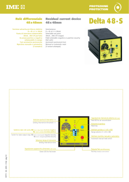
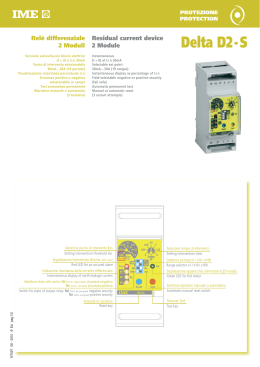
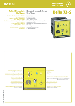
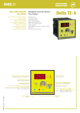
PROTEZIONE
PROTECTION
Sorvegliatore del
circuito di apertura
dell’interruttore,
con bobina a lancio di
corrente
4 Moduli
Garantisce l’affidabilità della protezione
differenziale sorvegliando l’efficienza del
circuito di sgancio, di uno o due interruttori
con bobina a lancio di corrente, segnalando
l’interruzione del circuito di apertura con
visualizzazione allarme (LED frontale) ed
intervento relè di uscita.
Utilizzabile in tutte le applicazioni che
impiegano il circuito della bobina a lancio di
corrente, per sorvegliarne l’efficienza
(es. circuiti di sicurezza, segnalazioni
acustiche e visive di stati di allarme, pompe
antincendio, ecc.)
Circuiti controllati 1 opp. 2 (selezionabile)
Tensione circuiti controllati 20...440Vca/cc
Visualizzazione allarme
Segnalazione allarme con
intervento relè uscita
F1
AC
Switch opening
circuit monitoring
unit with current
launching
coil
4 Module
Delta TCS
It guarantees the differential protection
reliability by monitoring the release circuit
working order of one or two switches with
current launching coil.
It reports the opening circuit breakdown by
displaying the alarm (front LED) and
intervention of output relay.
It can be used for all the applications which
provide for the use of circuits with current
launching coil to monitor its proper working
order (for instance security circuits, sound or
visual signalling of states of alarm,
fire pumps, etc…)
Controlled circuits 1 or 2 (selectable)
Controlled circuit voltage 20…440V ac/dc
Alarm display
Alarm detection with
output relay intervention
F2
DC
1
Test
2
0n
1
2
Ok Fault
Ok Fault
~
NT817 05 - 2012 1a Ed. pag.1/4
Ba
TD
L1
L2
L3
N
0ff
h.f.filter
CODICI DI ORDINAZIONE
ORDERING CODE
AL. AUSILIARIA
AUX. SUPPLY
ARD003
230V ca/ac
ARD00H
20...150Vcc/dc - 48Vca/ac
INGRESSO
INPUT
Circuiti controllati: 1 o 2 selezionabili
Controlled circuits: 1 or 2 selectable
Tensione circuito controllato: 20...440Vca/cc
Controlled circuit voltage: 20…440V ac/dc
Autoconsumo circuito controllato: ≤ 1mA
Controlled circuit rated burden: ≤ 1mA
PREDISPOSIZIONE
SETTING
Misura: circuito corrente continua (DC) opp. alternata (AC)
Measurement: direct current (DC) or alternating current (AC) circuit
Circuiti controllati: 1 bobina (F1) opp. 2 bobine (F2)
Controlled circuits: 1 coil (F1) or 2 coils (F2)
BOBINA COIL
1
Morsetti Terminals
1A - 1B
LED verde Green LED
Ok1
LED rosso Red LED
Fault1
Morsetti Terminals
R1 + R 2
Tasto Test Test Key
1
Ingresso Input
Sorveglianza Monitoring
Allarme Alarm
Relè Relay
Test Manuale Manual Test
FUNZIONE FUNCTION
F2
Ingresso Input
Sorveglianza Monitoring
Allarme Alarm
Relè Relay
Test Manuale Manual Test
BOBINA COIL
1
Morsetti Terminals
1A - 1B
LED verde Green LED
Ok1
LED rosso Red LED
Fault1
Morsetti Terminals
R1
Tasto Test Test Key
1
BOBINA COIL
2
Morsetti Terminals
2A - 2B
LED verde Green LED
Ok2
LED rosso Red LED
Fault2
Morsetti Terminals
R2
Tasto Test Test Key
2
SEGNALAZIONE
SIGNALLING
Sorveglianza (bobina non interrotta): LED verde “Ok”
Monitoring (coil not broken down): green LED “Ok”
Allarme (bobina interrotta): LED rosso “Fault” + commutazione relè
Alarm (broken down coil): red LED “Fault” + relay communication
CONTROLLO
CONTROL
Test manuale: verifica l’efficienza del sorvegliatore e del circuito di bobina
Manual test: it verifies the proper working order for monitoring unit and coil circuit
Nella funzione F2 sono disponibili 2 pulsanti di Test che consentono la
In the F2 function 2 Test keys which allow verifying each single circuit are
verifica di ogni singolo circuito
available
ALLARME
ALARM
Ritardo intervento: ≥ 1s
Delay: ≥ 1s
Ripristino: automatico
Reset: automatic
Ritardo ripristino: ≥ 1s
Reset delay: ≥ 1s
USCITA
OUTPUT
Funzione F1
Funzione F1
Relè: 2 contatti di scambio SPDT ( R1+R2)
Relay: 2 SPDT contacts (R1+R2)
Funzione F2
Funzione F2
Relè: 1 contatto di scambio SPDT (R1) + 1 contatto di scambio SPDT (R2)
Relay: 1 SPDT contact (R1) + 1 SPDT contact (R2)
Portata contatti: 5A 250Vca cosϕ 1 – 3A 250Vca cosϕ 0,4 – 5A 30Vcc
Contact range: 5A 250Vac cosϕ1 – 3A 250Vac cosϕ 0,4 – 5A 30Vdc
Sicurezza positiva/incondizionata (relè normalmente eccitato)
Positive security fail safe (normally energised relay)
NT817 05 - 2012 1a Ed. pag.2/4
FUNZIONE FUNCTION
F1
ALIMENTAZIONE AUSILIARIA
AUXILIARY SUPPLY
Valore nominale Uaux ca: 48 - 230V
Rated value Uaux ac: 48 - 230V
Variazione ammessa: 0,8...1,1Uaux ca – 40...60V(Uaux ca 48V)
Tolerance: 0,8...1,1Uaux ac – 40...60V(Uaux ac 48V)
Frequenza nominale: 50Hz
Rated frequency: 50Hz
Variazione ammessa: 47...63Hz
Tolerance: 47...63Hz
Autoconsumo: 2,5VA
Rated burden: 2,5VA
Valore nominale Uaux cc: 20...150Vcc
Rated value Uaux dc: 20...150Vdc
Protezione contro l’inversione di polarità
Protected against incorrect polarity
Autoconsumo: 2,5W
Rated burden: 2,5W
ISOLAMENTO
(EN/IEC60947-1)
Categoria di installazione: III
Installation category: III
Grado di inquinamento: 2
Pollution degree: 2
Tensione di riferimento per l’isolamento: 450V
Insulation reference voltage: 450V
Prova di tensione a impulso 5kV 1,2/50µs 0,5J
Impulse voltage test 5kV 1,2/50µs 0,5J
Circuiti considerati: ingresso, uscita relè, al. ausiliaria
Considered circuits: input, relay output, aux. supply
Prova a tensione alternata 2,5kV valore efficace 50Hz/1min
A.C. voltage test 2,5kV r.m.s. 50Hz/1min
Circuiti considerati: ingresso, uscita relè, al. ausiliaria
Considered circuits: input, relay output, aux. supply
Prova a tensione alternata 4kV valore efficace 50Hz/1min
A.C. voltage test 4kV r.m.s. 50Hz/1min
Circuiti considerati: tutti i circuiti e massa
Considered circuits: all circuits and earth
PROVE DI COMPATIBILITA’ ELETTROMAGNETICA
TESTS FOR ELECTROMAGNETIC COMPATIBILITY
Prove di emissione in accordo con EN/IEC 60947-2
Emission tests according to EN/IEC 60947-2
Prove di immunità in accordo con EN/IEC 60947-2
Immunity tests according to EN/IEC 60947-2
CONDIZIONI AMBIENTALI
ENVIRONMENTAL CONDITIONS
Temperatura di impiego: -5...50°C
Nominal temperature range: -5...50°C
Temperatura limite di funzionamento: -10...55°C
Limit temperature range: -10...55°C
Temperatura di magazzinaggio: -40...70°C
Limit temperature range for storage: -40...70°C
Umidità relativa (IEC60755): 50% (valore massimo a 40°C)
Relative humidity (IEC60755): 50% (highest value at 40°C)
Adatto all’utilizzo in clima tropicale
Suitable for tropical climates
Massima potenza dissipata : ≤ 2,5W
Max. power dissipation1: ≤ 2,5W
1
(EN/IEC60947-1)
For switchboard thermal calculation
1
1
CUSTODIA
HOUSING
Custodia: 4 moduli DIN43880
Housing: 4 module DIN43880
Connessioni: morsetti fissaggio a vite per conduttore fino a 4mm2
Connections: screw terminals for cable up to 4mm2
Montaggio: a incastro su profilato 35mm
Mounting: snap-on 35mm rail
Tipo profilato: a cappello TH35-15 (EN/IEC 60715)
Rail type: top hat TH35-15 (EN/IEC 60715)
Materiale custodia: policarbonato autoestinguente
Housing material: self-extinguishing policarbonate
Grado di protezione (EN/IEC 60529): IP40 frontale, IP20 morsetti
Protection degree (EN/IEC 60529): IP40 front frame, IP20 terminals
Peso: 260 grammi
Weight: 260 grams
Per il dimensionamento termico dei quadri
NT817 05 - 2012 1a Ed. pag.3/4
INSULATION
1A 1B
DIMENSIONI
S 291/132
F1
S 291/133
INPUT
ALARM
(+) (—)
R1
R2
70 71 72
80 81 82
AUX.
SUPPLY
70
INPUT 1
20 21
1A 1B
89,5
44
ALARM 1
70 71 72
45
INPUT 2
F2
R1
2A
2B
ALARM 2
R2
80 81 82
AUX.
SUPPLY
(+) (—)
20 21
La I.M.E. S.p.A. si riserva in qualsiasi momento, di modificare le caratteristiche tecniche senza darne preavviso. / I.M.E. S.p.A. reserves the right, to modify the technical characteristics without notice.
WIRING DIAGRAMS
NT817 05 - 2012 1a Ed. pag.4/4
SCHEMI D’INSERZIONE
DIMENSIONS
65,6
Scaricare