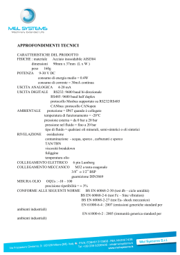
Evco S.r.l. • Code 104VVIEW0A00
Vview
User interface
version 1.00
GB ENGLISH
1
GETTING STARTED
1.1 Important
Read these instructions carefully before installing and using the instrument and follow all additional information for installation and electrical
connection; keep these instructions close to the instrument for future consultations.
The instrument must be disposed according to the local legislation about the collection for electrical and electronic
equipment.
4
ELECTRICAL CONNECTION
4.1 Electrical connection
2
INTRODUCTION
2.1 Introduction
Vview is a panel mounting user interface with 4 x 20 characters alphanumeric display to be used with the controllers belonging to the family
C-PRO MEGA or C-PRO GIGA.
The user interface can be connected both to a built-in controller (in this case it allows to repeat at a distance its user interface) and to a blind one
(in this case it allows to operate on it) through a non optoisolated CAN port; if you connect Vview to the local CAN port of the controllers belonging
to the family C-PRO MEGA or C-PRO GIGA, Vview will be supplied by the controller.
For further information consult the Hardware manual of C-PRO MEGA, the Hardware manual of C-PRO GIGA and the Application manual;
the product code of Vview is CPVXL0C.
3
SIZE AND INSTALLATION
3.1 Size
Size in mm (in).
Connector 1: CAN port.
PIN
MEANING
VDC
power supply (12 VDC)
+
signal +
signal GND
ground
Also look at the following settings of the controller:
• local CAN port termination
• local CAN port baud rate.
In the controllers belonging to the family C-PRO MEGA or C-PRO GIGA,
these settings can be done through jumpers JP3 and JP4.
4.2 Additional information for electrical connection
• do not operate on the terminal blocks with electrical or pneumatic
screwers
• if the instrument has been moved from a cold location to a warm
one, the humidity could condense on the inside; wait about an hour
before supplying it
• test the working power supply voltage, working electrical frequency
and working electrical power of the instrument; they must correspond with the local power supply
• connect the user interface to the controller using a twisted pair
• disconnect the local power supply before servicing the instrument
• do not use the instrument as safety device
• for repairs and information on the instrument please contact Evco
sales network.
5
TECHNICAL DATA
5.1 Technical data
Box: self-extinguishing grey.
Size: 159.0 x 159.0 x 95.0 mm (6.259 x 6.259 x 2.244 in).
Size refers to the user interface with the connector properly plugged.
Installation: panel mounting, with screw brackets (supplied by the
builder).
Frontal protection: IP 54.
Connections: extractable male terminal block (CAN port).
The maximum length of the connecting cables depends on the local
CAN port baud rate of the controller:
• 10 m (32.808 ft) with baud rate 20,000 baud
• 5 m (16.404 ft) with baud rate 50,000 baud
• 2 m (6.561 ft) with baud rate 125,000 baud
• 1 m (3.280 ft) with baud rate 500,000 baud.
The user interface recognizes the local CAN port baud rate of the controller automatically.
One suggests using the connecting kit CJAV05 (extractable female terminal block pitch 5.0 mm, 0.196 in; the kit is not supplied with the
controller).
Working temperature: from 0 to 50 °C (32 to 120 °F, 10 ... 90% of
relative humidity without condensate).
Power supply: 12 VDC, max. 0.2 A; if you connect Vview to the
local CAN port of the controllers belonging to the family
C-PRO MEGA or C-PRO GIGA, Vview will be supplied by the controller.
Alarm buzzer: incorporated.
Communication ports: 1 non optoisolated CAN port.
DIMENS.
MINIMUM
TYPICAL
MAXIMUM
A
134.0 (5.275)
134.0 (5.275)
134.8 (5.307)
B
134.0 (5.275)
134.0 (5.275)
134.8 (5.307)
3.2 Installation
Panel mounting, with screw brackets (supplied by the builder).
3.3 Additional information for installation
• the panel thickness must not be higher than 8.0 mm (0.314 in)
• working conditions (working temperature, humidity, etc.) must be
between the limits indicated in the technical data
• do not install the instrument close to heating sources (heaters, hot air
ducts, etc.), devices provided with big magnetos (big speakers, etc.),
locations subject to direct sunlight, rain, humidity, dust, mechanical
vibrations or bumps
• according to the safety legislation, the protection against electrical
parts must be ensured by a correct installation of the instrument; the
parts that ensure the protection must be installed so that you can not
remove them if not by using a tool.
I ITALIANO
1
IMPORTANTE
1.1 Importante
Leggere attentamente queste istruzioni prima dell’installazione e prima
dell’uso e seguire tutte le avvertenze per l’installazione e per il collegamento elettrico; conservare queste istruzioni con lo strumento per consultazioni future.
Lo strumento deve essere smaltito secondo le normative
locali in merito alla raccolta delle apparecchiature elettriche
ed elettroniche.
Buzzer di allarme: incorporato.
Porte di comunicazione: 1 porta CAN non optoisolata.
PT • 24/08
2
INTRODUZIONE
2.1 Introduzione
Vview è un’interfaccia utente per installazione a pannello con
visualizzatore alfanumerico 4 x 20 caratteri da utilizzare con i controllori
della famiglia C-PRO MEGA o C-PRO GIGA.
L’interfaccia utente può essere collegata sia a un controllore built-in (in
tal caso consente di ripeterne l’interfaccia utente a distanza) che a un
controllore cieco (in tal caso consente di operare su di esso) attraverso
una porta CAN non optoisolata; se si collega Vview alla porta CAN
locale dei controllori della famiglia C-PRO MEGA o C-PRO GIGA,
Vview sarà alimentato dal controllore.
Per ulteriori informazioni consultare il Manuale hardware di
C-PRO MEGA, il Manuale hardware di C-PRO GIGA e il Manuale
applicativo; il codice prodotto di Vview è CPVXL0C.
3
DIMENSIONI E INSTALLAZIONE
3.1 Dimensioni
Si veda il disegno della sezione in Inglese.
Le dimensioni sono espresse in mm (in).
3.2 Installazione
A pannello, con le staffe a vite in dotazione; si veda il disegno della
sezione in Inglese.
3.3 Avvertenze per l’installazione
• lo spessore del pannello non deve essere superiore a 8,0 mm
(0,314 in)
• accertarsi che le condizioni di lavoro (temperatura di impiego, umidità, ecc.) rientrino nei limiti indicati nei dati tecnici
• non installare lo strumento in prossimità di fonti di calore (resistenze,
condotti dell’aria calda, ecc.), di apparecchi con forti magneti (grossi
diffusori, ecc.), di luoghi soggetti alla luce solare diretta, pioggia,
umidità, polvere eccessiva, vibrazioni meccaniche o scosse
• in conformità alle normative sulla sicurezza, la protezione contro eventuali contatti con le parti elettriche deve essere assicurata mediante
una corretta installazione dello strumento; tutte le parti che assicurano la protezione devono essere fissate in modo tale da non poter
essere rimosse senza l’aiuto di un utensile.
4
COLLEGAMENTO ELETTRICO
4.1 Collegamento elettrico
Si veda il disegno della sezione in Inglese.
Connettore 1: porta CAN.
PIN
SIGNIFICATO
VDC
alimentazione (12 VCC)
+
segnale +
segnale GND
massa
Si vedano anche le seguenti impostazioni del controllore:
• terminazione porta CAN locale
• baud rate porta CAN locale.
Nei controllori della famiglia C-PRO MEGA o C-PRO GIGA, queste operazioni possono essere eseguite attraverso i jumper JP3 e JP4.
4.2 Avvertenze per l’installazione
• non operare sulle morsettiere utilizzando avvitatori elettrici o pneumatici
• se lo strumento è stato portato da un luogo freddo a uno caldo,
l’umidità potrebbe condensare all’interno; attendere circa un’ora prima di alimentarlo
• accertarsi che la tensione di alimentazione, la frequenza e la potenza
elettrica operativa dello strumento corrispondano a quelle dell’alimentazione locale
• collegare l’interfaccia utente utilizzando un doppino twistato
• disconnettere l’alimentazione prima di procedere con qualunque tipo
di manutenzione
• non utilizzare lo strumento come dispositivo di sicurezza
• per le riparazioni e per informazioni riguardanti lo strumento rivolgersi alla rete di vendita Evco.
5
DATI TECNICI
5.1 Dati tecnici
Contenitore: autoestinguente grigio.
Dimensioni: 159,0 x 159,0 x 95,0 mm (6,259 x 6,259 x 2,244 in).
Le dimensioni fanno riferimento all’interfaccia utente con il connettore
correttamente inserito.
Installazione: a pannello, con le staffe a vite in dotazione.
Grado di protezione del frontale: IP54.
Connessioni: morsettiere estraibili maschio (porta CAN).
La lunghezza massima dei cavi di collegamento dipende dalla baud
rate della porta CAN locale del controllore:
• 10 m (32,808 ft) con baud rate 20.000 baud
• 5 m (16,404 ft) con baud rate 50.000 baud
• 2 m (6,561 ft) con baud rate 125.000 baud
• 1 m (3,280 ft) con baud rate 500.000 baud.
L’interfaccia utente riconosce automaticamente la baud rate della porta CAN locale del controllore.
Si consiglia di utilizzare il kit di cablaggio CJAV05 (morsettiera estraibile
femmina passo 5,0 mm, 0,196 in; il kit non è in dotazione con il controllore).
Temperatura di impiego: da 0 a 50 °C (da 32 a 120 °F, 10 ... 90%
di umidità relativa senza condensa).
Alimentazione: 12 VCC, max. 0,2 A; se si collega Vview alla porta
CAN locale dei controllori della famiglia C-PRO MEGA o
C-PRO GIGA, Vview sarà alimentato dal controllore.
EVCO S.r.l.
This document belongs to Evco; unless you are authorized by Evco, you can not publish this document.
Via Mezzaterra 6, 32036 Sedico Belluno ITALY
Evco does not take any responsibility about features, technical data and possible mistakes related in this document.
Phone +39-0437-852468 • Fax +39-0437-83648
Evco does not take any responsibility about damages coming by the non-observance of additional information.
[email protected] • www.evco.it
Evco reserves the right to make any change without prior notice and at any time without prejudice the basic safety and operating features.
Scaricare