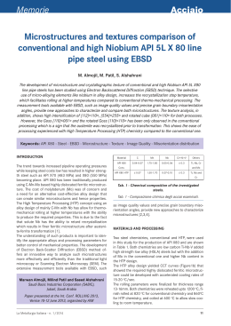
Memorie
Acciaio
On the strength of microalloyed steels
- An interpretive review
C. I. Garcia, M. Hua, K. Cho, A. J. DeArdo
In the mid-1950s, hot rolled carbon steels exhibited high carbon contents, coarse ferrite-pearlite
microstructures, and yield strengths near 300 MPa. Their ductility, toughness and weldability were poor.
Today, a half-century later, hot rolled steels can exhibit microstructures consisting of mixtures of ferrite,
bainite and martensite in various proportions. These structures are very fine and can show yield strengths over
900 MPa, with acceptable levels of ductility, toughness and weldability.
This advancement was made possible by the combination of improved steelmaking, microalloying
technology and better rolling and cooling practices. The purpose of this paper is to chronicle some of the
remarkable progress in steel alloy and process design that has resulted in this impressive.
KEYWORDS:
Accelerated cooling, direct quenching, EBSD-IQ, HSLA steel, strengthening,
thermomechanical processing, transformation
INTRODUCTION: MICROALLOYING AND STRENGTH
The year 1980 represents a benchmark in the strength of MA steels. From the early days of the 1960s to approximately 1980, the
steels being microalloyed were low hardenability steels with ferrite-pearlite (F-P) microstructures and yield strengths up to about
420 MPa (60 Ksi). These were the steels that were used to develop
the principles and interrelationships of microalloying, controlled
rolling and air cooling. They were characterized by relatively higher carbon contents and moderate Mn levels, and exhibited ferrite-pearlite (F-P) microstructures after air cooling (1).
Around 1980, both the linepipe and the automotive industries
desired strengths in excess of the 420 MPA that could be readily supplied with fine grained F-P steels. Clearly higher
strength microstructures were required. The obvious choices
were the lower temperature transformation products: matrices
comprised of non-polygonal ferrite, acicular ferrite, the bainites
and martensite, either as monoliths or as mixtures. To achieve
these microstructures, the combination of higher hardenability
and high cooling rates was required. Furthermore, much additional research was needed to reach the required goals consistently and with uniform results.
From the processing side, the solution to this dilemma was using
water cooling after hot rolling. This was accomplished in the
mid-1980s for plate processing by interrupted accelerated cooling (IAC) and interrupted direct quenching (IDQ) in plate mills.
Runout table water spray cooling to the coiling temperature in
hot strip mills had been in practice since the 1960s, but not as
C. Issac Garcia, Mingjian Hua,
Kengun Cho, A. J. DeArdo
BAMPRI (The Basic Metals Processing Research Institute)
Department of Mechanical Engineering and Materials Science - University of Pittsburgh, Pittsburgh,
Pennsylvania 15261, USA
Anthony DeArdo
Finland Distinguished Professor,
Department of Mechanical Engineering
University of Oulu, P.O. Box 4200 (Linnanmaa),
FIN-90014, Finland
Paper presented at the 3rd International Conference Thermomechanical
Processing of Steels, Padova, 10-12 september 2008, organized by AIM
la metallurgia italiana - n. 11-12/09
FIG. 1
Evolution of plate steel for large diameter linepipe:
microstructure and mechanical properties. (2)
Evoluzione dell’acciaio per lamiere destinato a
condutture di grande diametro: proprietà
microstrutturali e meccaniche. (2)
a microstructural control tool for increasing strength. This was
because of the higher carbon contents of the steels of that era.
The benefits of faster rates of cooling and lower coiling temperatures were exploited for achieving higher strengths later with
steels of lower carbon contents.
Figure 1 shows schematically how the microstructure and properties of plate steels changed over time with advances in alloy
design and processing (2).
It is obvious from Figure 1, that the accelerated cooling after rolling was largely responsible for the very high strengths attainable, practically independent of composition. With suitable cooling
practices, yield strengths in excess of 690 MPa (X100) can be
achieved in low carbon steels containing less than 2 Wt% Mn and
with C. E. and Pcm values near 0.5 and 0.2, respectively (3, 4).
One central question is what is the role of the MAE in obtaining
these strength levels? Let’s begin with the early steels (pre1980), where air cooling of plate and high coiling temperatures
of strip were used. As noted above, these were the F-P steels with
strengths up to about 420 MPa (X60) for gauges up to 18mm (0.7
inches). The most obvious contributor to strength was grain refinement, as was clearly shown by quantitative optical micro35
Memorie
Lattice Parameter, a0, nm
[100]ppt // [100] γ
[010]ppt // [010] γ
[001]ppt // [001] γ
[100]ppt // [100] α
[011]ppt // [010] α
[0-11]ppt // [001] α
NbC
NbN
VC
VN
4.4702
25.22
25.22
25.22
55.95
10.26
10.26
4.39
22.98
22.98
22.98
53.15
8.28
8.28
4.16
16.53
16.53
16.53
45.13
2.61
2.61
4.29
20.17
20.17
20.17
49.67
5.81
5.81
scopy. There is no doubt that the MAE was responsible for this
contribution through its effect on austenite conditioning. Other
contributions included solid solution strengthening by the Mn,
Si, and others, including the MAE, when retained in solution.
Equations have been published quantifying these effects, as well
(5). The other contribution to strength claimed by researchers
studying these early steels was precipitation hardening (6).
The precipitates expected to strengthen ferrite, NbCN, VCN, TiC,
TiN, all exhibit a NaCl crystal structure, and, as such, do not fit
well in the ferrite lattice. The lattice mismatch for Nb and V precipitates in both austenite and ferrite are shown in Table 1 (7).
This explains why the MA particles are always located on crystalline defects in either the austenite or ferrite (7). The misfit
strains of several percent mean that the particles cannot be coherent. The combination of incoherency with the ferrite and the
NaCl structure means that the particles must cause strengthening by the Orowan-Ashby mechanism, Eq. 1 (8-10).
(1)
This mechanism of strengthening for the Orowan process is by: (a)
the energy required for dislocations to bow between particles, and
(b) the energy required by the cross slipping of screw segments
FIG. 2
The dependence of precipitation strengthening on
precipitate size (X) and fraction according to the
Ashby-Orowan Model, compared with experimental
observations for given microalloying additions. (10)
Dipendenza dell’ indurimento per precipitazione dalla
dimensione (X) e dalla frazione in volume dei precipitati
secondo il modello Ashby-Orowan, confrontata con
osservazioni sperimentali a seguito di aggiunte mirate di
microalliganti. (10)
36
TAB. 1
Lattice mismatch for MX
precipitates in austenite and
ferrite, % Austenite: fcc, a0 =
0.35698 nm; Ferrite: bcc, a0
= 0.28664 nm.
Differenze dei parametri
reticolari per precipitati MX
nell’ austenite e nella ferrite,
% Austenite: fcc, a0 = 0.35698 nm;
Ferrite: bcc, a0 = 0.28664 nm.
or climb of edge dislocation segments in bypassing the particles
(9). The predicted increase in YS caused by this mechanism depends on the amount or volume fraction of precipitate and the
size of the particles. This is shown for particles in ferrite in Figure 2 by Gladman for several precipitation systems (10).
The data of Figure 2 must be used with caution, however. First,
the volume fraction or amount used in the calculation is that actually consumed in forming the particles. The amount lost to the
austenite in rolling and the amount remaining in solid solution
do not contribute to the strength shown in Figure 2 and must be
subtracted from the total. Second, the precipitates participating
are those actually present in the steel, and, therefore, need time
to form in the ferrite. An early example of the slow kinetics for
this precipitation was shown by Honeycombe and Sakuma (11,
12), Figure 3, and later confirmed by Thillou, et al. (13)
Third, claims of precipitation hardening and the application of
Figure 2 should be independently verified by thin foil TEM.
Fourth, the mere presence of fine particles in ferrite does not
guarantee precipitation hardening. The distribution must conform to the Orowan-Ashby model to justify claims of a certain
level of strengthening. Finally, it must be recognized that isothermal laboratory experiments do not necessarily predict the
behavior of continuously cooled commercial steels, even when
the compositions are similar.
Plots of the Orowan-Ashby equation as viewed from what must
be observed in thin foil TEM are shown in Figure 4 (14,15).
These plots show what precipitate distributions must be present,
viz. measured, to claim 10, 50 and 100 MPa increments in YS
caused by precipitation hardening. Superimposed are reasona-
FIG. 3
Schematic TTT curves for Fe-0.036Nb-0.09C and Fe0.036Nb-0.09C-1.07Mn alloys. Interphase
precipitation (IP) occurs in certain shaded areas.
Curve TTT schematiche per leghe Fe-0.036Nb-0.09C
eFe-0.036Nb-0.09C-1.07Mn. La precipitazione interfase
(IP) si verifica entro le aree tratteggiate.
la metallurgia italiana - n. 11-12/09
Acciaio
that found by solution hardening and bake hardening or strain
aging (16), and is nowhere near what can be found by dislocation
or substructure strengthening of ferrite (16-18).
In discussions of precipitation hardening in MA steels, the cooling path from the finish rolling temperature is critical to the
formation of strengthening particles (7, 11, 12). While air cooling at 1°C/sec from 750-600°C in 150 sec. might be slow
enough to form strengthening precipitates, Figure 5 (19), water
spray cooling through the temperature range 750-600°C at 1050°C/sec is probably much too fast to form effective particle distributions in rolled and cooled steels.
In summary, the major role of the MAE in strengthening the pre1980 steels was mainly by grain refinement. To this was probably added some solid solution and dislocation strengthening.
The contribution by precipitation hardening is not zero, but has
been probably over estimated. This was pointed out in several
early studies (20, 21).
The strength of these steels can be understood by Equation (2),
the expanded Hall-Petch equation.
(2)
FIG. 4 Particle dispersion characteristics for precipitate
strengthening according to Orowan-Ashby theory.
(14,15)
Caratteristiche della dispersione delle particelle
all’origine dell’ indurimento per precipitazione secondo
la teoria Orowan-Ashby. (14, 15)
FIG. 5
Interphase precipitation of NBCN in ferrite in steel
containing .09%C - .07%Nb. Specimen reheated at
1250°C, rolled at 1000°C, and air cooled to RT. (19)
Precipitazione interfase di NbCN nella ferrite di un in
acciaio contenente .09%C - .07%Nb. Campioni
riscaldati a 1250° C e raffreddati in aria fino a
temperatura ambiente. (19)
ble levels of both particle size and volume fractions. The predictions of Figures 4 and 5 are fully consistent with the data of
Figure 2. The Gladman diagram shown in Figure 2 represents
the maximum strengthening increments that can be expected
when conditions for precipitation are ideal, i.e. full precipitation
of available components. Again, the abscissa in Figure 2 is the
volume fraction actually formed, not what is predicted from the
bulk composition. In commercially processed hot rolled steels, it
is extremely rare that increments caused by precipitation hardening exceed 50-80 MPa (16). This magnitude is comparable to
la metallurgia italiana - n. 11-12/09
where YSobs is the observed yield strength; YSP-N, YSSS, YStexture,
YSdisl, YSpptn are the stress increments caused by lattice friction
(Peierls-Nabarro), solid solution, texture, dislocations, and precipitation; and Kyd–1/2 represents the contribution by the ferrite
grain size.
For the F-P steels of the 1970s, the dominant contribution to
strength was Kyd–1/2, with much smaller contributions from YSSS,
YSdisl, and YSpptn.
MODERN STEELS
As was noted earlier, in the 1980s there was a large emphasis on
increasing the strength from the 420 MPa (API-X60) level to over
490 (API X-70). On the process side, this challenge was met by
lowering the transformation temperature of the austenite during
the cooling after hot rolling. On plate mills, this was accomplished by interrupted accelerated cooling (IAC) and later by interrupted direct quenching (IDQ). On strip mills it was achieved
by increasing the cooling rate and lowering the coiling temperature. In plate rolling, controlled rolling followed by air cooling
has been termed TMP, while controlled rolling followed by IAC
or IDQ has been called TMCP in some quarters (22).
It is well known that accelerated cooling can increase the
strength of F-P steels by reducing the ferrite grain size, as shown
in numerous studies (20,23). What is less clear is that rapid cooling leading to refined polygonal ferrite also leads to higher ferrite grain center hardness, as shown by Morikawa and
Hasegawa, Figure 6 (24).
The 0.15C-0.66Mn steel used in Figure 6 showed that the ferrite
grain center hardness, viz., a volume not thought to be strongly
influenced by grain boundaries or grain refinement, increased
substantially with cooling rate from about 100Hv at 1°C/sec to
near 140Hv at 100°C/sec. This increase was attributed to higher solute C and excess dislocations present in the rapidly cooled ferrite. No bainite was observed until cooling rates exceeded
25°C/sec. in this experiment. This extra strengthening was attributed to the combination of higher solute carbon levels trapped in rapidly cooled ferrite and to higher dislocation densities.
MULTI-PHASE MATRIX MICROSTRUCTURES
The equally important change with cooling rate involves the matrix microstructure. It is obvious from Figure 1 that the difference between the 420 and >490 MPa grades is the nature of
37
Memorie
the matrix (2). As noted earlier, the 420 MPa grade shows polygonal ferrite formed at high transformation temperatures, over
perhaps 600°C. The matrix in higher strength steels shows mixtures of ferrite and bainite and/or martensite, in different proportions. In general, the higher the proportion of bainite and
martensite, the higher the strength of the steel.
As the strength level increases, the steels change character from
monolithic ferrite to complex mixtures starting with ferrite-bainite, ferrite-martensite, monolithic bainite, and finally monolithic martensite. With mixed microstructures, the steels appear
to follow the Rule of Mixtures, as shown by Davies in Figure 7 for
ferrite-martensite mixtures found in DP automotive steels (25).
The influence of MAE on the transformation characteristics of controlled rolled and cooled steels can be profound, especially at higher rates of cooling. An example of this effect is shown in Figures
8-10 (7,26) for transformation start temperatures, resulting microstructures and final mechanical properties, respectively (7, 26).
FIG. 6
Effect of cooling rate on strengthening factors of
steel 1. (24)
Effetto della velocità di raffreddamento sui fattori di
indurimento dell’acciaio 1. (24)
FIG. 7
The 0.2% flow stress and the tensile strength
as a function of percent martensite for Fe-Mn-C
alloys. (25)
Limite di snervamento allo 0,2% e carico di rottura in
funzione della percentuale di martensite per le leghe FeMn-C. (25)
FIG. 9
Effects of Nb, V and Ti on volume fraction of bainite
and ferrite grain size in accelerated cooled steels
(7, 26).
Effetti di Nb, V e Ti sulla frazione in volume della diverse
dimensioni dei grani di bainite e ferrite in acciai
sottoposti a raffreddamento accelerato (7, 26)
FIG. 8
Corrected Ar3 temperatures
of microalloyed steels with
standard austenite grain size
of 100µm (7, 26).
Temperature Ar3 corrette per
acciai microlegati con
dimensione standard del grano
austenitico (100mm) (7, 26).
38
la metallurgia italiana - n. 11-12/09
Acciaio
FIG. 10 Effects of addition of Nb. V and Ti on tensile strength
and Charpy V 50% FATT of (1) air cooled, (2)
accelerated cooled and (3) direct quenched steels
after controlled rolling (7, 26).
Effetti dell’aggiunta di Nb, V e Ti sulla resistenza a trazione
e sulla 50% FATT Charpy V di acciai (1) raffreddati ad aria,
(2) sottoposti a raffreddamento accelerato e (3) temprati
direttamente dopo laminazione controllata (7, 26)
The positive synergy between the MAE and accelerated cooling
is significant. Figure 10 reveals that the addition of 0.04 wt%
Nb to the base steel adds about 10% to the strength after air cooling; accelerated cooling with Nb adds about 40% and DQ with
Nb adds about 76%. Other examples show how the addition of
Nb, Figure 11 or V, Figure 12, to a 0.07C - 1.55Mn - 0.018Ti reference steel has little effect on the final microstructure after air cooling but a large effect after
accelerated cooling, especially on strength (27).
MONOLITHIC MICROSTRUCTURES
It is well-known that low carbon and ultra-low
carbon bainitic and martensitic ferrite can exhibit remarkable properties. Yield strengths in excess of 850 MPa (X120) in 12-18mm plate and
strip have been achieved in MA steels processed
using TMCP (3, 4). Two obvious questions are: (i)
what can cause the strength to essentially double
from the early 350-420MPa grades to the newer
700-850MPa grades, and (ii) what is the role, if
any, of the MAE?
It is well known that the strength of bainite and
martensite is controlled mainly by the carbon
content and the Bs or Ms temperature (28, 29),
Figure 13. The data of Figure 13 were generated
with ULCB plate steels with rich chemistries intended for heavy gauge applications (29).
Attempts have been made to relate the properties of bainite to its microstructure, but with limited success (30-32). With falling temperature
and increasing strength, the sequence of upper
bainite, granular bainite, then lower bainite is
often observed. Although these microconstituents have different appearances in the OM,
their real microstructure must be revealed by
thin foil TEM. Since this is a very tedious and expensive proposition, little of this work has been
done. What is clear from the available literature
is that with falling Bs temperature, both the soluble carbon content and the dislocation density
increase. This is why the strength increases with
falling transformation temperatures. The main
reason that the soluble carbon content increases
with falling temperature can be related to the sloping upper ferrite solvus and T0 lines on the FeFe3C phase diagram and the Hultgren
extrapolation that exist in the absence of cementite (33, 34). They predict that in the absence
of equilibrium, viz. presence of Fe3C, higher cooling rates will lead to higher carbon contents
with falling temperature. This, together with the
large solution hardening capability of carbon and
the concomitant increase in the dislocation density resulting from the combination of the volume change and the shear-type nature of the
transformation will combine to result in higher
la metallurgia italiana - n. 11-12/09
FIG. 11 Effect of Nb content on properties of plate (27). CR denotes
controlled rolling and air cooling; ACC denotes controlled rolling
and accelerated cooling.
Effetti del contenuto di Nb sulle proprietà dei laminati (27). CR indica
laminazione controllata e raffreddamento ad aria; ACC indica
laminazione controllata e raffreddamento accelerato.
FIG. 12 Effect of V content on properties of plate (27)
Effetto del contenuto di V sulle proprietà dei laminati (27).
39
Memorie
strengths with falling temperature.
One way to characterize the microstructure, one that avoids the
confusion and complexity of labeling and characterizing the observed ultra-fine detail, is through the use of EBSD-IQ, a technique recently applied to microstructure assessment in advanced
steels (35). In the EBSD–IQ technique, once the specimen surface and beam stability effects have been eliminated, the quality
of the final diffraction peaks coming from the Kikuchi lines is
measured, processed and quantified (35). Highly elastically distorted lattices yield low IQ peaks since the diffraction profile is
smeared, not unlike line broadening due to elastic strain in x-ray
diffraction (36). Near-perfect lattices yield high IQ peaks, because the peaks in the diffraction pattern are narrow and sharp.
Since both solute elements, viz. C and N, and dislocations as well
as precipitates might contribute to lattice strain, the EBSD-IQ
approach to understanding the strength of bainite and martensite appears to be promising.
Recent work using the EBSD-IQ technique has shown that multiphase microstructures can be characterized and quantified
using this approach. In this technique, the EBSD-IQ data are first
processed and then plotted using the Multi-Peak Software (35).
The resulting plots show a spectrum of multiple peaks where
the peak height is proportional to the volume fraction of that microconstituent and the location on the abscissa is related to the
inverse of the lattice distortion. As noted above, this distortion
is assumed to come from the combination of lattice strain caused by the dislocation density, solute content and particles.
Typical examples are shown for studies involving HSLA strip, Figures 14 and 15 (35,37, 38), DP steel, Figure 16 (35,39), TRIP-assisted steels (40), heat treated seamless pipe, Figure 17 (38) and
bainitic plate steels, Figure 18 (41). It is clear that this technique
can discern details of the final microstructure, including the
components of multi-phase mixtures.
The first example of applying the EBSD-IQ technique to multiphase microstructures is to an HSLA hot band structure with an
optical microstructure as shown in Figure 14. Analyzing this
complex microstructure using the EBSD-IQ approach resulted if
the multi-peak profile shown in Figure 15. Notice the several
forms of ferrite present in the microstructure.
The next example is a DP steel where the amounts of ferrite and
martensite were measured in three ways; by point counting, by
image analysis and the third by EBSD-IQ. The IQ results are
shown in Figure 16. The phase balance values determined with
the three approaches fell within a few percent (35,39).
Another example is heat treated seamless pipe that shows a mixture of autotempered and untempered martensite after tempering.
The EBSD-IQ analysis of this steel is shown in Figure 17 (38).
Finally, the EBSD-IQ approach has been applied to bainitic steel
plates. The IQ analysis of this study revealed the multi-peak result shown in Figure 18 (41).
When considering the strength of the bainite or martensite, either as a monolithic matrix or as part of mixed microstructures,
certain aspects must be considered. First, there are relatively
few high angle boundaries present in the microstructure. Therefore Hall-Petch strengthening will not be important. Second,
very little precipitation hardening can be expected in these rapidly cooled steels, at least in the as-cooled condition (42).
Hence, the strength of the bainite and/or martensite will be go-
FIG. 14 Optical micrograph of a HSLA steel hot band.
Etched with 2% Nital. (35,37)
Micrografia ottica di un nastro a caldo in acciaio HSLA.
Attacco Nital 2%. (35, 37)
FIG. 13 Comparison of measured and calculated strength
values for a given Bs temperature. (29)
Confronto dei valori di resistenza meccanica misurati e
calcolati per una determinata temperatura Bs. (29)
40
FIG. 15 The IQ analysis of the HSLA hot band
microstructure shown in Figure 14 using the MultiPeak model. (35,38)
Analisi IQ della microstruttura del nastro a caldo in
acciaio HSLA mostrato in Fig. 14 mediante modello
Multi-Peak (35, 38)
la metallurgia italiana - n. 11-12/09
Acciaio
verned by the contributors to lattice distortion, viz. solutes, dislocations and their interaction. Early examples of these strong
dislocation effects were shown by Smith and Honeycombe (17),
Mangonon and Heitmann (18), and Repas (43).
The influence of dislocation density or subgrain size on strength
can be very much higher than those from solid solution and precipitation, where increments of 30-80 MPa are typical. Manganon and Heitmann have shown that substructure hardening of
ferrite can easily exceed 200MPa, Figure 19 (18). This is a contribution that can also be expected in bainite and cannot be overlooked.
In summary, when the strength of bainite is considered through
the lens of the expanded Hall-Petch equation, the contributions
from YSdisl and YSss are probably most important and the contributions from high angle grain boundaries and precipitation
are secondary.
have nearly doubled in strength while still maintaining adequate, if not superior levels of other important properties such
as toughness, weldability, ductility, formability, etc. These improvements have been facilitated by evolutions of steelmaking,
rolling and cooling practices. The details of the improvements
have been chronicled and are largely understood. Perhaps the
main message learned over the past 50 years, or so, is that microstructural improvement and optimization are often not a simple extrapolation of the old to the new. Sometimes we need a
new box.
REFERENCES
1.
2.
3.
CONCLUSIONS
It is no surprise that the microstructures of the 200-420 MPa
YS steels of the 1960s and 1970s are very different from those of
the >490 grades of today. It is rather amazing that the steels
FIG. 16 IQ analysis of DP steel microstructure using multipeak model. (35)
Analisi IQ di una microstruttura di acciaio DP mediante
modello Multi-Peak (35)
FIG. 17 The Image Quality (IQ) distribution analysis of the
specimen cooled by 10°C/sec, A508 Gr4N steel.
Analisi di distribuzione con Image Quality (IQ) del
provino di acciaio A508 Gr4N raffreddato a 10°C/s.
la metallurgia italiana - n. 11-12/09
4.
Proc. Microalloying 75 (Washington, DC), Union Carbide Corp., New
York, 1977.
M. K. Graff, H. G. Hillenbrand and P. A. Peters, “Accelerated Cooling
of Plate for High-Strength Large Diameter Pipe,” Accelerated Cooling of Steel, TMS-AIME, Warrendale, PA, USA, 1986, 165-180.
H. Asahi et al., “Development and Properties of Ultra High-strength
UOE Pipeline,” Proc. IPC 2004, International Pipeline Conference,
Oct. 4-8, 2004, Calgary, Alberta, Canada, ASME 2004, paper #
IPC04-0230.
D. Bai, L. Collins, F. Hamad, X. Chen, and R. Klein, “Microstructure
and Mechanical Properties of High Strength Linepipe Steels,”
FIG. 18 EBSD IQ multi-peak analysis of a bainitic steel.
Analisi EBSD IQ multi-peak di un acciaio bainitico.
FIG. 19 Regression line between subgrain size (d) and its
strengthening effect (∆σSG). Note that d–1/2 = 30,
40 and 50 is equivalent to approximately 1.1, 0.63
and 0.4 µm cell size, respectively.
Linea di regressione fra dimensione del sottograno (d) e
il suo effetto di indurimento (∆σSG). Notare che d–1/2 =
30, 40 e 50 è equivalente a una dimensione di cella
rispettivamente di circa 1,1 - 0,63 - 0,4 µm.
41
Memorie
5.
6.
7.
8.
9.
10.
11.
12.
13.
14.
15.
16.
17.
18.
19.
20.
21.
22.
23.
24.
25.
26.
27.
28.
29.
30.
31.
32.
33.
34.
35.
42
MS&T07, 355-366.
H. Yada: “Prediction of Microstructural Changes and Mechanical
Properties in Hot Strip Rolling,” Accelerated Cooling of Rolled Steel,
ed. by G. E. Ruddle and A. F. Crawley, Pergamon Press, New York
(1988), 105.
W. B. Morrison, Journal of the Iron and Steel Institute, 201, 317
(1963).
A. J. DeArdo, “Niobium in Modern Steels,” International Materials
Reviews, Vol. 48, No. 6, (2003), pp.371-402.
J. Friedel, Dislocations (Oxford: Pergamon Press, 1967).
L. M. Brown, R. H. Cook, R. K. Ham, G. R. Purdy, Scripta Metallurgica, Vol. 7, (1973), 815-820.
T. Gladman, D. Dulieu and I. D. McIvor, “Structure-Property Relationships in High Strength Microalloyed Steels,” Microalloying 75,
Union Carbide Corporation, New York, NY, USA, 32-55.
T. Sakuma and R. W. K. Honeycombe, Met. Sci., 18 (1984), 449-454.
T. Sakuma and R. W. K. Honeycombe, Mater. Sci. Technol., 1 (1985),
351–356.
V. Thillou, M. Hua, C. I. Garcia, C. Perdrix, and A. J. DeArdo, “Precipitation of NbC and Effect of Mn on the Strength Properties of
Hot Strip HSLA Low Carbon Steels,” Prod. International Conference,
“Microalloying in Steels: New Trends for the 21st Century,” San Sebastian, 7-9 September, 1998, Editors: J. M. Rodriguez-Ibabe, I. Gutiérrez and B. López, pp. 311-318.
C. Parish, Unpublished Research, BAMPRI, University of Pittsburgh, 2001.
Jinghui Wu, Unpublished Research, BAMPRI, University of Pittsburgh, 2001.
M. Hua, Unpublished Research, BAMPRI, University of Pittsburgh,
2005.
R. G. Smith and R. W. K. Honeycombe, Proc. 6th Int. Conf. on
Strength of Metals and Alloys, Melbourne, (1982), 407.
P. L. Mangonon, Jr., and W. E. Heitmann, Microalloying 75, Union
Carbide Corporation, New York, NY, 1977, 59-70.
M. I. Santella, “Grain growth and high-temperature hot rolling behavior of low-alloy steel austenite’, PhD thesis, University of Pittsburgh, PA, 1981, 49.
T. Parayil and G. Ludkovsky, Proc Accelerated Cooling of Rolled
Steel, Pergamon Press, New York, 1988, 131-146.
A. Itman, K. R. Cardoso and H. –J. Kestenbach: Mater. Sci. Technol.,
13 (1997), 49–55.
H. Tamehiro, et al., “Application of Accelerated Cooling After Controlled Rolling to Line Pipe Steel,” Proc. Third International Conference on Steel Rolling: Technology of Pipe and Tube and Their
Application., Iron & Steel Inst. of Japan, 1985, 545-551.
Proc. Accelerated Cooling of Steel, Aug. 19-21, 1985, Pittsburgh,
TMS-AIME, 1986.
H. Morikawa and T. Hasegawa, Proc. Accelerated Cooling of Steel,
Aug. 19-21, 1985, Pittsburgh, TMS-AIME, (1986), 83-96.
R. G. Davies, “Influence of Martensite Composition and Content on
the Properties of Dual Phase Steels,” Metall. Trans. A, Vol. 9A,
(1978), 671.
S. Okaguchi, T. Hashimoto and H. Ohtani: Proc. Conf. Thermec’88,
Vol. 1, 1988, Tokyo, Iron and Steel Institute of Japan, 330-336.
H. Tamehiro, et al, Proc. Accelerated Cooling of Steel, Aug. 19-21,
1985, Pittsburgh, TMS-AIME, 1986., 401-413.
F. B. Pickering: Microalloying '75, Union Carbide Corp., New York,
NY (1977), 9.
C.I. Garcia and A.J. DeArdo, "Structure and Properties of ULCB
Plate Steels for Heavy Section Applications", Microalloyed HSLA
Steels, (ASM International: 1988), 291-300.
H. Ohtani, et al. Metall. Trans. A, Vol. 21A (1990), 877-888.
A. B. Cota and D. B. Santos, Materials Characterization, Vol. 44
(2000), 291-299.
M. Diaz-Fuentes, A. Iza-Mendia, I. Gutierrez, Metall. Mater. Trans.
A, Vol.34A (2003), 2505-2516.
M. Takahashi et al., Proc. Intern. Conf. On TRIP-Aided High
Strength Ferrous Alloys, Ghent, June 19-21, 2002, 103-111.
H. Matsuda, et al, ibid, 112-119.
Jinghui Wu, Peter J. Wray, Calixto I. Garcia, Mingjian Hua and Anthony J. DeArdo, “Image Quality Analysis: A New Method of Characterizing Microstructure,” ISIJ International, Vol. 45 (2005) No. 2,
pp254-262.
36. C. S. Barrett and T. B. Massalski, Structure of Metals, McGraw-Hill,
New York, 1966, p. 459.
37. J. Wu, P. J. Wray, C. I. Garcia, M. Hua, A. J. DeArdo, “On achieving
a better understanding of the polygonal ferrite microstructure in if
steel using image quality analysis,” Materials and Manufacturing
Processes, vol. 22, no. 2, February, 2007, p 281-285.
38. J. Wu, C. I. Garcia, M. Hua, W. Gao, K. Cho, and A. J. DeArdo, “A
New Method of Characterizing and Quantifying Complex Microstructures in Steels,” Invited Paper, Steel Product Metallurgy and
Applications, Organized by B.D. Nelson, and M.J. Merwin, Materials Science and Technology (MS&T) 2006: Product Manufacturing, Materials (ACerS, AIST, ASM, and TMS), pp.305-316.
39. K. Cho, C. I. Garcia, H. Shu, T. R. Chen and A. J. DeArdo, “Development of the 590 - 780 - 980 Nb-Bearing Dual-Phase Steels for Production on Continuous Galvanizing Lines,” Proceedings
International Conference on Microalloyed Steels: Processing, Microstructure, Properties and Performance Proceedings, Edited by A.
J. DeArdo and C. I. Garcia, July 16-19, 2007, Pittsburgh, PA, AIST,
Warrendale, PA, (2007), p313-323.
40. C. I. Garcia, M. Hua, K. Cho and A. J. DeArdo, “EBSD-IQ: A New Method of Characterizing and Quantifying Complex Microstructures
in Steels,” Proceedings International Conference on Microalloyed
Steels: Processing, Microstructure, Properties and Performance
Proceedings, Edited by A. J. DeArdo and C. I. Garcia, July 16-19,
2007, Pittsburgh, PA, AIST, Warrendale, PA, (2007), p335-344.
41. K. Cho, EBSD Analysis on Bainitic Plate Steel, Unpublished Research, BAMPRI, University of Pittsburgh, 2007.
42. D.Q. Bai, F. Hamad, J. Asante, and S. Hansen, “Precipitation Strengthening in a Low Carbon Nb- Microalloyed Steel,” Materials
Science Forum Vols. 500-501 (2005), 481-488
43. P. E. Repas, “Metallurgical Fundamentals for HSLA Steels,” Microalloyed HSLA Steels, ASM International, 1988, 3-14.
Abstract
Rassegna sulla resistenza
degli acciai microlegati
Parole chiave: acciaio, lavorazioni plastiche, proprietà
A metà degli anni 1950, gli acciai al carbonio laminati a caldo
avevano un alto contenuto di carbonio, microstrutture a
grossi grani di ferrite-pearlite, e un limite di snervamento
intorno a 300 MPa. La loro duttilità, tenacità e saldabilità
erano scarse. Oggi, mezzo secolo più tardi, gli acciai laminati a caldo possono presentarsi con microstrutture costituite da combinazioni di ferrite, bainite e martensite in varie
proporzioni. Queste strutture sono molto fini e sono in grado
di esibire una resistenza allo snervamento superiore a 900
MPa, con livelli accettabili di duttilità, tenacità e saldabilità.
Questo sviluppo è stato reso possibile dalla combinazione dei
miglioramenti nella produzione dell’ acciaio, nella tecnica di
microalligazione e nelle procedure di laminazione e raffreddamento. Lo scopo di questo documento è quello di riportare
una cronaca di alcuni dei maggiori progressi nell’alligazione
dell'acciaio e nella progettazione dei processi, che hanno portato a questo straordinario risultato.
la metallurgia italiana - n. 11-12/09
Scaricare