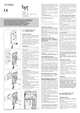
Mod.
1750
DS 1750-003A
LBT 8963
VIDEOCITOFONO A COLORI 2VOICE
2VOICE COLOUR VIDEO DOOR PHONE
VIDEOPHONE COULEURS 2VOICE
VIDEOINTERFONO COLOR 2VOICE
FARB-VIDEOANLAGE 2VOICE
Sch./Ref.1750/1
ITALIANO
Il videocitofono Sch.1750/1 è dedicato all’utilizzo in impianti videocitofonici del sistema 2Voice.
Descrizione dei componenti e caratteristiche
1
7
2
8
3
4
9
5
6
10
11
12
1.
2.
3.
4.
5.
6.
7.
8.
12
Tasto apriporta
Led verde presente sotto al tasto apriporta
Pulsante
Pulsante
Pulsante
Led bicolore
Morsetti per collegamento al sistema
Dip-switch di configurazione:
a. 2 per definire il numero del posto interno all’interno dell’appartamento
b. 8 per definire il numero dell’appartamento nella colonna
Per le impostazioni dei dip-switch fare
riferimento al libretto di sistema
ON
=
ON
=
9. Predisposizione per collegamento entra-esci con accessorio Sch. 1750/50
10. Luminosità
11. Colore
12. Viti di bloccaggio del videocitofono alla staffa
T
Posizionare il selettore in modalità T.
Dispositivo compatibile con tutte
le protesi acustiche con modalità
di
funzionamento
T
(Norme
ETS 300381 e EN 60118).
DS1750-003A
descrizione dei morsetti
]
]
LINE IN
Connessione al BUS di sistema
CP
Chiamata al piano
S+
S-
} Ripetizione di chiamata
Installazione
•
•
•
Fissare la staffa a parete utilizzando una scatola 503 e le viti in dotazione o una scatola Ø 60 con viti
adeguate.
Programmare i dip-switch di programmazione.
Collegare alla morsettiera i conduttori provenienti dall’impianto.
Agganciare il monitor alla staffa e bloccarlo avvitando le viti A di fissaggio.
Scatola Ø 60
1,40 m
1,40 m
Scatola 503
1,40 m
•
A
A
Ø 4 mm max
punta a taglio o
croce phillips
DS1750-003A
FUNZIONE PULSANTI
STATO
IN FONIA
RIPOSO E
SGANCIATO
STATO DI
PROGRAMMAZIONE*
(SOLO CON
VIDEOCITOFONO A
RIPOSO E AGGANCIATO)
Apriporta
pedonale
Apriporta
pedonale
Apriporta pedonale
Abilita/disabilita apriporta
automatico
Scorrimento
memoria video
Funzione
speciale
(default: 7)
Funzione
speciale
(default: 7)
Chiamata
intercomunicante
3 programmabile
(default: non
programmato)
Regolazione volume di
chiamata citofonica e al
piano (il volume cambia
secondo la sequenza
ALTO,BASSO,MUTE)
Autoinserzione
Palleggiamento
video
Funzione
speciale
(default: 8)
Chiamata
intercomunicante
2 programmabile
(default: non
programmato)
Scelta suoneria chiamata al
piano (5 suonerie diverse)
Chiamata
intercomunicante
1 programmabile
(default: chiamata a
centralino)
Scelta suoneria chiamata
citofonica
(5 suonerie diverse)
RIPOSO E
AGGANCIATO
ATTESA
SGANCIO
(ricezione
chiamata)
Apriporta
pedonale
PULSANTE
Apriporta passo Apriporta passo Apriporta passo
carraio
carraio
carraio
(*) Per entrare o uscire dallo stato di programmazione premere e tenere premuto il tasto per più di
5 secondi; la conferma dell’entrata in programmazione avviene con il lampeggio lento del led giallo;
comunque allo scadere della temporizzazione di 10 min si esce dallo stato di programmazione.
Segnalazioni LED
2. Led verde acceso.
Segnala la ricezione di una chiamata.
6. Led bicolore.
priorità
Funzioni
1
Rosso lampeggiante veloce: mute attivo
2
Verde lampeggiante: apriporta automatico attivo
3
Rosso acceso fisso: porta aperta sul posto di chiamata principale
4
Rosso lampeggiante lento: porta aperta sul posto di chiamata secondario
5
Giallo lampeggiante lento: stato di programmazione attivo
Per salvare la programmazione ricordarsi di uscire dalla stessa tenendo premuto il tasto per
più di 5 secondi; comunque trascorsi 10 minuti il dispositivo esce dallo stato di programmazione
salvando i parametri variati.
Per la programmazione della chiamata intercomunicante fare riferimento al libretto di sistema.
RESET
Per ripristinare i parametri di default del dispositivo, dopo l’ingresso in programmazione con la pressione
del tasto per più di 5 secondi, premere contemporaneamente i tasti e
per più di 3 secondi; la
conferma del comando avviene con l’emissione di 2 beep lunghi e l’uscita del dispositivo dallo stato di
programmazione.
DS1750-003A
ENGLISH
The Ref.1750/1 video door phone is dedicated to the 2Voice system video door phones.
DESCRIPTION OF COMPONENTS AND FEATURES
1
7
2
8
3
4
9
5
6
10
11
12
1.
2.
3.
4.
5.
6.
7.
8.
12
Door opener button
Green LED under door opening button
Button
Button
Button
Two-colour LED
Terminals for connecting to the system
Configuration dip switch:
a. 2 to define the station number in the apartment
b. 8 to define the apartment number in the column
Refer to the system booklet for how to
set the dip switches.
ON
DS1750-003A
=
ON
=
9. In-out connection setup with Ref. 1750/50
10. Brightness
11. Colour
12. Screws for fixing video door phone to bracket
T
Put the selector in mode T.
Device
compatible
with
all
hearing aids with operating mode
T (Standards ETS 300381 and
EN 60118).
DESCRIPTION OF TERMINALS
]
]
LINE IN
System bus connection
CP
Floor call
S+
S-
} Call repetition
InstallaTION
•
•
•
Fix the bracket to the wall using a box 503 and the screws provided or a Ø 60 box with suitable
screws.
Program the dip switches.
Connect the wires from the system to the terminal board.
Couple the monitor to the bracket and lock it by screwing fastening screws A.
Ø 60 box
1,40 m
1,40 m
503 box
1,40 m
•
A
A
Ø 4 mm max
slotted head or
Phillips cross head
DS1750-003A
BUTTON FUNCTIONS
STATE
RINGING
STANDING BY ON-HOOK
ON-HOOK
(RECEIVING
CALL)
DURING
AUDIO
OPERATION
STANDING BY
OFF-HOOK
BUTTON
PROGRAMMING
STATE*
(WITH VIDEO DOOR
PHONE STANDING BY
ON-HOOK)
Open
pedestrian
door
Open
pedestrian
door
Open
pedestrian
door
Connect / disconnect the
Open pedestrian
automatic door opening
door
system
Scroll video
memory
Special
function
(default: 7)
Special
function
(default: 7)
Programmable
intercom call
3 (Default: not
programmed)
Adjust door phone and
floor call volume (volume
changes according to
the following sequence:
LOUD, LOW, MUTE)
Auto power-on
Video
switching
Special
function
(default: 8)
Programmable
intercom call
2 (Default: not
programmed)
Floor call ring tone (5
different ring tones)
Garage door
opener
Garage door
opener
Garage door
opener
Programmable
intercom call
Door phone call ring tone
1 (Default:
(5 different ring tones)
switchboard call)
(*) To enter and exit programming state, hold button pressed for longer than 5 seconds. The yellow LED
will blink slowly to indicate that programming mode is selected. Programming mode will shut down in all
cases after the 10 minute timeout.
INDICATOR LEDS
2. Green LED on.
Indicates that a call is being received
6. Two-colour LED.
prioritY
FunCTIONS
1
Rapidly blinking red: mute on
2
Green blinking: automatic door opener on
3
Red on steady: main calling station door open
4
Slowly blinking red: secondary calling station door open
5
Slowly blinking yellow: programming state on
To save programming, remember to hold the button pressed for longer than 5 seconds to quit
programming mode. In any case, after 10 minutes the system exits the programming state and
saves the modified parameters.
Refer to the system booklet for how to program intercom calls.
RESET
To restore default parameters of the device after entering programming mode, hold button pressed for
longer than 5 seconds, hold buttons and hold
pressed for longer than 3 seconds. The system will emit
two long beeps to confirm the command and exit the programming state.
DS1750-003A
FRANÇAIS
Le vidéophone Réf.1750/1 est conçu pour être utilisé dans les installations de vidéophonie du système
2Voice.
DESCRIPTION DES COMPOSANTS ET CARACTERISTIQUES
1
7
2
8
3
4
9
5
6
10
11
12
1.
2.
3.
4.
5.
6.
7.
8.
12
Touche ouvre-porte
LED verte située sous la touche ouvre-porte
Bouton
Bouton
Bouton
LED bicolore
Bornes de connexion au système
Commutateur de configuration:
a. 2 pour définir le numéro du poste interne dans l’appartement
b. 8 pour définir le numéro de l’appartement dans la colonne
Pour les réglages des commutateurs, se
reporter à la notice de système.
ON
=
ON
=
9. Pré-câblage pour le raccordement
entrée-sortie avec accessoire Réf. 1750/50
10. Luminosité
11. Couleur
12. Vis de fixation du vidéophone à l’étrier
T
Positionner le sélecteur sur T.
Dispositif compatible avec les prothèses
auditives avec mode de fonctionnement
T (Dispositions ETS 300381 et EN
60118).
DS1750-003A
DESCRIPTION DES BORNES
]
]
LINE IN
Connexion au BUS de système
CP
Appel à l’étage
S+
S-
} Répétition appel
InstallaTION
•
•
•
Fixer l’étrier à la paroi en utilisant un boîtier 503 et les vis livrées de série, ou bien un boîtier Ø 60 avec
des vis appropriées.
Régler les commutateurs de programmation.
Brancher les connecteurs en provenance de l’installation sur le bornier.
Accrocher l’écran à l’étrier et le bloquer en vissant les vis de fixation A.
Boîtier Ø 60
1,40 m
1,40 m
Boîtier 503
1,40 m
•
A
A
Ø 4 mm maxi
bout plat ou
cruciforme Phillips
DS1750-003A
FONCTIONS DES BOUTONS
ETAT
BOUTON
ATTENTE
REPOS ET
DECROCHAGE
RACCROCHAGE (RECEPTION
APPEL)
Ouvre-porte
piétons
Ouvre-porte
piétons
Défilement
mémoire
vidéo
Fonction
spéciale
(par défaut: 7)
PHONIE
REPOS ET
DECROCHAGE
ETAT DE
PROGRAMMATION
(*)
(VIDEOPHONE
AU REPOS ET
RACCROCHE)
Activation/
désactivation ouvreporte automatique
Réglage du volume
Appel intercom d’appel d’interphone
Fonction
3 programmable
et à l’étage (le
spéciale
(par défaut: non volume varie selon
(par défaut: 7)
programmé)
la séquence HAUT,
BAS, MUTE)
Ouvre-porte
piétons
Ouvre-porte
piétons
Activation
automatique
Renvoi vidéo
Appel intercom
Fonction
Sélection sonnerie
2 programmable
spéciale
d’appel à l’étage (5
(par défaut: non
(par défaut: 8)
sonneries différentes)
programmé)
Ouverture
passage pour
véhicules
Ouverture
passage pour
véhicules
Appel intercom
Sélection sonnerie
Ouverture
1 programmable d’appel d’interphone
passage pour
(par défaut: appel
(5 sonneries
véhicules
vers centrale)
différentes)
(*) Pour accéder ou quitter l’état de programmation, maintenir le bouton enfoncé pendant plus de 5
secondes; le clignotement lent de la LED jaune confirme l’accès à la programmation. Au bout de 10
minutes, le système quitte automatiquement l’état de programmation.
SIGNALISATIONS PAR LED
2. LED verte allumée.
Signale la réception d’un appel.
6. LED bicolore.
prioritE
FOnCTIONS
1
Rouge, clignotement rapide: fonction Mute active
2
Vert, clignotement: ouvre-porte automatique actif
3
Rouge, lumière fixe: porte ouverte sur poste d’appel principal
4
Rouge, clignotement lent: porte ouverte sur poste d’appel secondaire
5
Jaune, clignotement lent: état de programmation actif
Pour enregistrer la programmation, quitter celle-ci en maintenant le bouton enfoncé pendant
plus de 5 secondes. Au bout de 10 minutes, le dispositif quitte en tout cas l’état de programmation,
en enregistrant les paramètres modifiés.
Pour la programmation de l’appel intercom, se reporter à la notice de système.
RESET
Pour rétablir les paramètres par défaut du dispositif, après l’accès à la programmation en maintenant le
bouton enfoncé pendant plus de 5 secondes, appuyer en même temps sur les boutons et
pendant
plus de 3 secondes; la commande est confirmée par l’émission de 2 bips sonores prolongés et par la sortie
du dispositif de l’état de programmation.
10
DS1750-003A
ESPAÑOL
El videointerfono Ref. 1750/1 está destinado al uso en instalaciones videointerfónicas del sistema 2Voice.
DESCRIPCIÓN DE LOS COMPONENTES Y CARACTERÍSTICAS
1
7
2
8
3
4
9
5
6
10
11
12
1.
2.
3.
4.
5.
6.
7.
8.
12
Tecla de apertura de la puerta
Led verde presente debajo de la tecla de apertura de la puerta
Pulsador
Pulsador
Pulsador
Led bicolor
Bornes para la conexión al sistema
Interruptor dip de configuración:
a. 2 para definir el número del aparato interior dentro del apartamento
b. 8 para definir el número del apartamento en la columna
Para las configuraciones de los
interruptores dip, consultar el manual
de sistema.
ON
DS1750-003A
=
ON
=
9. Preparación para la conexión entrar-salir con accesorio Ref. 1750/50
10. Brillo
11. Color
12. Tornillos de bloqueo del videointerfono en el soporte
T
Posicionar el selector en modalidad T.
Dispositivo compatible con todas las
prótesis acusticas con modalidad de
funcionamiento T (Norma ETS 300381 y
EN 60118).
11
DESCRIPCIÓN DE LOS BORNES
]
]
LINE IN
Conexión al BUS de sistema
CP
Llamada al piso
S+
S-
} Repetición de llamada
INSTALACIÓN
•
•
•
Fijar el soporte de pared utilizando una caja 503 y los tornillos entregados con el equipo, o una caja Ø
60 con tornillos apropiados.
Programar los interruptores dip de programación.
Conectar al tablero de bornes los conductores que llegan del sistema.
Enganchar el monitor en el soporte y bloquearlo enroscando los tornillos de fijación A.
Caja Ø 60
1,40 m
1,40 m
Caja 503
1,40 m
•
A
A
Ø 4 mm máx
punta plana o
en cruz Phillips
12
DS1750-003A
FUNCIÓN DE LOS PULSADORES
ESTADO
EN REPOSO
Y COLGADO
ESPERA DE
RESPUESTA
(RECEPCIÓN
LLAMADA)
EN FONÍA
EN REPOSO Y
DESCOLGADO
ESTADO DE
PROGRAMACIÓN*
(SÓLO CON
VIDEOINTERFONO
EN REPOSO Y
COLGADO)
Apertura de la
puerta para
peatones
Apertura de
la puerta para
peatones
Apertura de
la puerta para
peatones
Apertura de
la puerta para
peatones
Activa/desactiva la
apertura automática
de la puerta
Llamada
intercomunicante
3 programable
(predeterminado:
no programado)
Regulación volumen
de llamada interfónica
y al piso (el volumen
cambia según la
secuencia ALTO,
BAJO, SILENCIO)
PULSADOR
Recorrer
memoria vídeo
Autoactivación
Apertura de la
puerta del pasaje
de vehículos
Función especial Función especial
(predeterminado: (predeterminado:
7)
7)
‘Rebote vídeo’
Llamada
Función especial intercomunicante
(predeterminado:
2 programable
8)
(predeterminado: no
programado)
Apertura de la
Apertura de la
puerta del pasaje puerta del pasaje
de vehículos
de vehículos
Llamada
intercomunicante
1 programable
(predeterminado:
llamada a la
centralita)
Selección del timbre
de llamada al piso
(5 timbres distintos)
Selección del timbre
de llamada al piso
(5 timbres distintos)
(*) Para entrar o salir del estado de programación, pulsar y mantener pulsada la tecla durante más de
5 segundos; la confirmación de la entrada en programación se produce con el parpadeo lento del led
amarillo; en todos los casos, cuando se cumple la temporización de 10 min. se sale del estado de
programación.
INDICACIONES DE LOS LED
2. Led verde encendido.
Indica la recepción de una llamada.
6. Led bicolor.
prioriDAD
FUNCIONES
1
Rojo parpadeante rápido: silencio activado
2
Verde parpadeante: apertura automática de la puerta activada
3
Rojo encendido fijo: puerta abierta en el puesto de llamada principal
4
Rojo parpadeante lento: puerta abierta en el puesto de llamada secundario
5
Amarillo parpadeante lento: estado de programación activado
Para guardar la programación, recordarse de salir de la misma manteniendo pulsada la tecla
durante más de 5 segundos. En todos los casos, después de 10 minutos el dispositivo sale del
estado de programación y se guardan los parámetros modificados. Para la programación de la
llamada intercomunicante, consultar el manual de sistema.
RESET
Para restablecer los parámetros predeterminados del dispositivo, después de entrar en programación
pulsando la tecla durante más de 5 segundos, pulsar simultáneamente las teclas y
durante más
de 3 segundos; la confirmación del mando se produce con la emisión de 2 bips prolongados y la salida del
dispositivo del estado de programación.
DS1750-003A
13
DEUTSCH
Die Videoanlage Typ 1750/1 ist speziell für die Verwendung in Videoanlagen des Systems 2Voice
bestimmt.
GERÄTEBESCHREIBUNG UND GERÄTEDATEN
1
7
2
8
3
4
9
5
6
10
11
12
1.
2.
3.
4.
5.
6.
7.
8.
12
Türöffnertaste
Grüne Led unter der Türöffnertaste
Taste
Taste
Taste
Zweifarbige Led
Klemmen für den Systemanschluss
Konfigurationsschalter:
a. 2 zum Festlegen der Nummer der Innenstelle im Inneren der Wohnung
b. 8 zum Festlegen der Nummer der Wohnung in der Steigleitung
Hinsichtlich
der
Einstellungen
des
Kodierschalters
siehe
Systemhandbuch.
ON
14
=
ON
=
9. Vorbereitung für die Ein-Ausgabe-Verbindung mit Zubehör Typ 1750/50
10. Helligkeit
11. Farbe
12. Befestigungsschrauben der Videoanlage an der Halterung
T
Den Schalter im T-Modus positionieren.
Vorrichtung
Hörgeräten
(Normen
EN 60118).
kompatibel mit allen
mit T Betriebsmodus
ETS
300381
und
DS1750-003A
ANSCHLUSSKLEMMEN
]
]
LINE IN
Anschluss an den System-BUS
CP
Etagenruf
S+
S-
} Rufwiederholung
INSTALLATION
•
•
•
Anbauhalterung mit einer Einbaudose 503 und den beiliegenden Schrauben oder einer Runddose Ø 60
und entsprechenden Schrauben an der Wand befestigen.
Die Programmierschalter programmieren.
Die von der Anlage kommenden Leiter an die Klemmenleiste anschließen.
Den Monitor an der Halterung anbringen und durch Verschrauben der Befestigungsschrauben A
fixieren.
Einbaudose Ø 60
1,40 m
1,40 m
Einbaudose 503
1,40 m
•
A
A
max. Ø4 mm
Schlitz- oder Kreuzschraubenzieher Phillips
DS1750-003A
15
TASTENFUNKTION
STATUS
RUHESTELLUNG
UND EINGEHÄNGT
WARTEZEIT
ABHEBEN
(RUFEINGANG)
IM GESPRÄCH
RUHESTELLUNG
UND ABGEHOBEN
PROGRAMMIERSTATUS*
(NUR BEI VIDEOANLAGE
IN RUHESTELLUNG MIT
AUFGELEGTEM HÖRER)
Türöffnerbefehl
Türöffnerbefehl
Türöffnerbefehl
Türöffnerbefehl
Automatischen Türöffner ein/ausschalten
Durchlauf
Videospeicher
Sonderfunktion
(Standard: 7)
Sonderfunktion
(Standard: 7)
Programmierbarer
Intercom-Anruf 3
(Standard: nicht
programmiert)
Einstellung der Ruflautstärke
der Sprechanlage und auf
der Etage (die Lautstärke
wechselt in Folge von HOCH,
NIEDRIG, MUTE)
Selbsteinschaltung Videobildübertragung
Sonderfunktion
(Standard: 8)
Programmierbarer
Intercom-Anruf 2
(Standard: nicht
programmiert)
Auswahl Läutwerk Etagenruf
(5 verschiedene Läutwerke)
Türöffner der Einfahrt Türöffner der Einfahrt
Türöffner der
Einfahrt
Programmierbarer
Intercom-Anruf 1
(Standard: Ruf an
die Zentrale)
Auswahl Läutwerk
Sprechanlagenruf (5
verschiedene Läutwerke)
TASTE
(*) Um sich in den Programmierstatus zu begeben oder diesen zu verlassen, die Taste länger als
5 Sekunden gedrückt halten. Die Bestätigung des Beginns des Programmierstatus erfolgt durch
langsames Blinken der gelben Led. In jedem Fall verlässt man nach Ablauf des Takts von 10 Minuten
den Programmierstatus.
LED-ANZEIGEN
2. Grüne Led eingeschaltet:
Signalisiert den Empfang eines Anrufs.
6. Zweifarbige Led.
PRIORITÄT
FUNKTIONEN
1
Rot schnell blinkend: Mute aktiv
2
Grün blinkend: automatischer Türöffner aktiv
3
Rot durchgehend eingeschaltet: Tür auf Hauptrufstelle geöffnet
4
Rot blinkend eingeschaltet: Tür auf Nebenrufstelle geöffnet
5
Gelb langsam blinkend: Programmierstatus aktiv
Um die Programmierung zu speichern, daran denken, diese zu verlassen, indem die Taste
länger als 5 Sekunden betätigt wird. In jedem Fall verlässt das Gerät nach Ablauf von 10 Minuten
den Programmierstatus und speichert die geänderten Parameter.
Zur Programmierung des Intercom-Rufs siehe Systemhandbuch.
RESET
Um die werkseitigen Parameter des Geräts nach dem Zugriff auf die Programmierung durch Betätigen
der Taste wieder herzustellen, gleichzeitig die Tasten und
länger als 3 Sekunden betätigen.
Die Bestätigung des Befehls erfolgt durch Aussenden von 2 langen Pfeiftönen und das Verlassen des
Programmierstatus von Seiten des Geräts.
1750-003A
DS
URMET S.p.A.
10154 TORINO (ITALY)
VIA BOLOGNA 188/C
Telef.
+39 011.24.00.000 (RIC. AUT.)
Fax
+39 011.24.00.300 - 323
LBT 8963
Area tecnica
servizio clienti +39 011.23.39.810
http://www.urmet.com
e-mail: [email protected]
Fabbricato da Urmet Electronics Limited
(azienda del gruppo Urmet) - Made in P.R.C.
Manufactured by Urmet Electronics Limited
(an Urmet group company) - Made in P.R.C.
Scarica