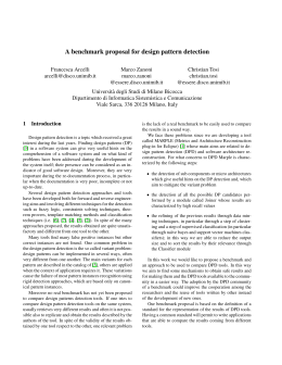
Experiencing AUML for the WINK Multi-Agent
System
Sonia Bergamaschi, Gionata Gelati, Francesco Guerra, Maurizio Vincini
Department of Information Engineering
University of Modena and Reggio Emilia
Italy
Email: [email protected], [email protected], [email protected], [email protected]
Abstract— In the last few years, efforts have been done
towards bridging the gap between agent technology and de facto
standard technologies, aiming at introducing multi-agent systems
in industrial applications. This paper presents an experience done
by using one of such proposals, Agent U M L. Agent U M L is
a graphical modelling language based on U M L. The practical
usage of this notation has brought to suggest some refinements
of the Agent U M L features.
I. I NTRODUCTION
In the last decade agent technology has been a mainstream
research area. Though many relevant advancements and results
have been achieved in the field, multi-agent systems have not
become widespread as industrial and commercial applications.
Recently, some efforts have been done towards bridging the
gap between agent technology and methodologies or technologies accepted for real world applications. These aim at
relating multi-agent systems to practical standards in order
to leverage on existing knowledge and tools. Opening agent
technology to industry means proposing the new technology
as ”an incremental extension” [3] of proven practices.
It is the case of object-oriented software design and development, which relies on well-established and trusted methods.
One of these is the Unified Modelling Language (U M L) [6],
a widely accepted notation for designing software systems according to the object-oriented paradigm. Extensions to U M L
to fit in notions related to software agents and multi-agent
systems have been proposed [1], [2], [3], [11], [12]. Thanks to
a cooperation between the Foundation of Intelligent Physical
Agents (F IP A, www.fipa.org) and the Object Management
Group (OM G, www.omg.org) these extensions have been
coherently collected and known as Agent UML (AU M L,
www.auml.org).
In this paper, we present our experience about applying
AU M L diagrams to design a real world application. The
use case is given by the system developed in the W IN K
European project (Web-linked Integration of Network based
Knowledge IST-2000-28221). For the scope of the paper, we
will focus on the subsystem charged of keeping the system
data up-to-date. Our experience has lead to some observations
on the suitability and usefulness of the proposed extensions,
together with some suggestions for further improvements.
Throughout the paper, we refer to AU M L as the set of
working drafts available on the AU M L web-site and on the
published scientific papers on AU M L [2], [3], [11], [12]. As
the status of the specifications is not stable, these contributions
show some degree of dissimilarity. Whenever required by
the context, we will point out which of the aforementioned
contributions we refer to. Further, while reporting on our
experience, we will highlight the extensions we have found
useful for our work. For the sake of plainness, all proposed
extensions are also summarized in Section VI.
The paper is structured as follows. In Section II, we set
the background for our work. Section III provides a basic understanding of the W IN K system while Section IV
presents the high-level requirements related to our use case
subsystem. Section V reports the application of AU M L to
the conceptual and implementation design of our use case.
Finally, conclusions are drawn in Section VI.
II. BACKGROUND
Research on agent-based software development has been
a very important discipline for agent technology. In the last
few years a number of methods have been proposed to the
scientific community. The field is characterized by a variety of
approaches, surveyed in [13]. Some recent methodologies are
most interesting to us. The Gaia methodology [17] proposes
to break the process in an analysis stage and a design stage. In
both stages, designers are required to deal with models (roles
model and interaction model for the analysis stage and agent
model, services model and acquaintance model for the design
stage). This way, designers and developers are progressively
guided through specifying more and more details about the application and the system, being encouraged to follow a process
based on organizational design. The T ropos methodology [10]
is based on two features: the notions of agent, goal, plan and
other agent related concepts are coherently used throughout
the process and requirements analysis and specification are
an essential part of the methodology. At the core of the
methodology there is the T ropos Modelling Language which
is based on a metamodel and is conceived as an extensible
language. Commonalities between the two methodologies are:
•
•
they distinguish a conceptual and an implementation or
development phase during the overall process;
they use different models to catch different views of
the system-to-be. These views concerns the following
aspects of agenthood: agents, environments, interactions
and organizations;
• they support not only agent-based systems, but are aware
that real applications envisage a blend of object-oriented
services and agent technology.
These features are also present in AU M L, a graphical modelling language. The first moves towards AU M L have been
made by Odell et al. [14]. U M L Class diagrams have been
revisited in [2] and further extended in [11]. While Bauer
et al. proposed a base form of Class Diagrams, Huget gave
a precise semantics to the relationships intercurring between
agents and between agents and objects. Huget further redefined
the compartments of a Class Diagram taking a Vowel [7]based approach. U M L Sequence and State diagrams have
been initially extended in [1]. This has brought to the definition
of a new Class of Diagrams, called Protocol Diagrams. Bauer
at al. included in Protocol Diagrams agent roles, threads of
interactions, nested and interleaved protocols and protocol
templates. Protocol Diagrams have been subsequently refined
in [12]. To the basic set of primitives, Huget added new features such as broadcasting, synchronization, triggering actions,
exception handling, time management, atomic transactions
and repeated messages, leveraging on his experience in the
domain of reliability, electronic commerce and supply-chain
management.
III. WINK OVERVIEW
The W IN K project [4] aims at supporting large-scale
multi-supplier and multi-site projects, usually known as oneof-a-kind production. The W IN K system implements a socalled integration network process model that helps managers
plan and monitor all aspects related to project management
such as personnel, resources, planning, exception handling and
budgeting. The main features of the W IN K system are:
• advanced planning and budgeting functionalities, which
lead to better forecasting, reducing re-planning overheads
during the execution of the projects;
• alert-based activity monitoring, which reduces cost and
risk assessment;
• management of contingent factors, including pro-active
analysis of deterministic and casual risk factors, replanning to face deviations, impact verification and solution comparison, re-alignment of plans and budgets for
the involved project units, change-tracking mechanisms
for revision evaluations;
• full exploitation of the network potential, by describing
its resources, competencies and operating processes, and
speeding up and automating information processes during
the entire project life cycle, spanning companies and
organizational unit boundaries.
From an architectural viewpoint, the W IN K project aims
at combining two existing systems, the Gruppo Formula’s
W HALES and the M IKS [5] from University of Modena
and Reggio Emilia. The goal is to compose an architecture that
leverages the strength of both systems. Figure 1 depicts the
Fig. 1.
The overall W IN K system architecture
resulting three-tier model: The W IN K architecture (Figure
1) is based on a three-tier model where the client tier makes
available a Virtual Integrated Cockpit on which information
is collected and presented as a customized web interface, the
data tier manages the interactions with the data provided by
the Enterprise Information Systems, and the business logic
tier combines the capabilities of two separated modules: the
Project Collaboration Portal and the Integration Framework.
In particular, the first module supports the definition of business logic for the monitoring, the execution and the planning
of a project. The Integration Framework provides a global
virtual view representing all the sources and an engine, based
on agent technology, to query distributed data sources. We
observe that all the W IN K tiers may be distributed on the
net and have to communicate with each other.
IV. S YSTEM R EQUIREMENTS
The multi-agent subsystem we consider in this paper is
charged of supporting the execution of tasks that involve functionalities of both the W HALES and the M IKS systems.
We can also see the subsystem as an application integration
module as it enhances the interoperability between the two
existing systems. From an operative perspective the subsystem
should function as follows. The W IN K users interact with a
web interface. Whenever new data have to be retrieved, users
are presented an Interface Module (that can be rendered for
instance by means of a dynamic web page by the Project
Collaboration Portal) where they can compose the query to
be submitted. Once the query is ready and submitted, the
Interface Module invokes an appropriate web service, which
acts upon the WINK Agency in order to activate the agents that
will be charged of the query execution and result delivery. The
query to be executed is handed on to a Service Agent together
with the notification the query has to be executed on a regular
basis. The Service Agent exploits the GV V to know which
data sources are involved by the posed query. According to this
mapping and to the contingent system workload, the Service
Agent will contact a number of Query Agents. At this stage,
aggregation: an agent is aggregate of another if it has a
recursive architecture;
• dependency: it is a mutual dependency between the linked
agents.
Huget states also the meaning of the relationships that can
be applied between an agent and a class:
• association: the agent uses the connected classes for their
execution;
• generalization: not possible;
• aggregation: the agent is defined as an aggregation of
several classes;
• dependency: the agent needs the class either in its code
or during its execution.
For the graphical notation associated to these relationships see
[11].
Although we find this semantics well-defined, there is room
for some observations. Let us consider the association relationship between agents. Looking at Figure 2 above, it could be
the case of the Query Agent and the Wrapper Agent that are
to be considered acquainted and can exchange messages. We
find this view is not properly correct. We should note that
the Query Agent relies upon the Wrapper Agent in order to
deliver the result to the Service Agent. The relationship is not
only of acquaintance (the Query Agent knows which Wrapper
Agent to contact and consequently, the Wrapper Agent knows
the Query Agent which started the conversation), but there is
a sort of cooperation between the two. How to capture this
aspect using AU M L class diagram is not yet clear to us. For
the time being, the only way we have found is to consider the
relationship as a dependency. We claim this is not generally
suitable, as cooperation and coordination are different from
dependency.
Consider now the possible relationships between an agent
and a class. We claim using classes has to be considered
as a general case. In order to give a finer semantics, we
suggest to extend the definition proposed in [Hug02a] by
distinguishing classes into service classes (or simply services)
and behavior classes ( or simply behaviors). Following our
proposal, the meaning of the diverse type of relationships has
to be anew stated as follows (we paraphrase Huget’s definition
to underline the change in meaning):
• association: the association relationship connects an agent
to the service classes it exploits. It means that this agent
uses the connected service classes for their execution;
• aggregation: the aggregation between agents and behavior
classes implies that agents are defined as an aggregation
of several behaviors, i.e. an agent can show the set of
connected behaviors (no matter whether they are statically or dynamically acquired). Agents usually comprise
several parts such as a reasoning side, an interaction side
and a perception side: they can all be seen as an agent
acquiring some behavior class (for reasoning, interacting,
perceiving);
• dependency: the dependency between agents and service
classes is possible and means that one agent needs the
•
Fig. 2.
Our reference subsystem
a Query Agent will move to the data source(s)/container(s)
the query refers to, will interact with Wrapper Agents in
order to execute the local query(ies) and finally will report
the answer to the calling Service Agent. In order to deliver
results so as to update the correct information, Service Agents
have been implemented in order to report query answers in
the desired format (in our case, an XM L format). The calling
Interface Module will then apply the desired XSL stylesheet
to present data on the W IN K web interface. Figure 2 depicts
this scenario, where the Interface Module is relieved by an
ASP page:
V. A PPLICATION OF AGENT UML D IAGRAMS
In this section we report our experience in using AU M L
Class and Protocol Diagrams. We first present the conceptual
level of abstraction and then the implementation view.
A. Class Diagrams: Conceptual Level
The conceptual level of design is intended to provide an
overview of the system, representing the different agents
and classes that compose it and the relationships intercurring
among these entities. The fact that both agents and classes can
be described and interrelated using a uniform notation is a step
towards the understanding of complex systems as composed
by a blend of object-oriented and M AS technology. We find
this is a very realistic approach to industrial and commercial
applications.
AU M L notation extends the U M L notation. Besides
classes, we distinguish of course agents, identified by the
stereotype <<agent>>. Besides the U M L relationships association, generalization, aggregation and dependency defined
between classes, the same set of relationships has been proposed in [12] for agent-agent and agent-class relationships,
giving them a semantics under the light of agent properties.
According to Huget, the meaning of the relationships that can
be applied between agents can be summarized as follows:
• association: the linked agent are acquainted and can
exchange messages;
• generalization: the definition of an agent can be derived
from other agents;
Fig. 4.
Implementation level of our scenario
details to data sources, passing the query to be executed;
agent-agent association: the Directory Agent and the
Query Agent can exchange messages as a Query Agent
must register to the Directory Agent when it is started;
• agent-agent generalization: the Basic Agent collects all
common features an agent in the M IKS system must
have.
Part (A) gives a first overview of the subsystem. The conceptual level design can be further refined, starting from the
relationships established in part (A) and focusing on smaller
parts of the subsystem. For instance, a Service Agent should
be capable of calling external services and communicating
with other agents. We can thus draw a Class Diagram which
models these features, still remaining at a conceptual level
of abstraction (no details on operations and variables are
given). Part (B) gives a first insight on the Service Agent.
It is an aggregate of a set of behaviors (for communicating
with external services, for storing data, for communicating).
Part (A) and (B) can be obviously combined in one single
diagram.
•
Fig. 3.
Conceptual level of our scenario
services during its execution since the agent would possibly exploit the service execution. A dependency between
agents and behavior classes is also possible, but it would
have the same semantics as aggregation.
It follows that, at least for the classes that are connected
to some agent, we should specify their type. For this purpose, we have introduced the stereotypes <<service>> and
<<behaviour>>. Figure 3 depicts the Class Diagram for
our use case scenario. It concerns the conceptual level of our
design since no details about attributes or operations are given.
We have used packages to organize objects into groups as
defined in U M L [6].
In part (A) we can recognize the following:
•
•
•
•
class-class associations: in the W HALES package we
can navigate between the Interface Module service and
the Business Object service as there is a relationship
concerning the data that have to be used and asked for;
class-class dependency: it is a unilateral dependency. A
change in the specification of the Platform Controller
service may affect methods that are used by the Interface
Module service;
agent-class association: the Service Agent uses the connected Business Object service for manipulating the data
on the W HALES server, not otherwise accessible;
agent-agent dependency: the pairs Service Agent - Directory Agent and Query Agent - Wrapper Agent are formed
by agents that are somehow dependent on each other.
The Service Agent asks for available agents which match
some properties to the Directory Agent. The Query Agent
exploits the Wrapper Agent for managing connection
B. Class diagrams: Implementation level
This level of abstraction develops the implementation phase.
Details have to be fully specified. In general, in order to
provide a comprehensive view of a system involving agents,
we have to specify facts about the architecture of agents and
their features, the interactions that can happen among them,
the environment that supports their execution and how they
can organize or be organized as a community. This concepts
or a subset of them can be found in a number of proposed
methodologies [Woo00, Giu02]. These methodologies help
designers focussing on the following aspects of agenthood:
• the agency view, which deals with agent’s knowledge,
belief, intentions, plans and behaviors;
• the environmental view, which models how agents react
to external changes;
• the interactional view, where interaction protocols are
specified;
• the organizational view, which gives details on organizations to which an agent belongs.
Taking into consideration the use case of the Service Agent
and the Basic Agent, we obtain the following Class Diagram
(Figure 4):
From the conceptual level we know the Service Agent and
the Basic Agent are linked with a generalization relationship.
As the Basic Agent is a sort of template for all other agents
we use, only the needed compartments are present, specifying
the attributes and operations (internal, pro-active and reactive)
shared by all agents in the subsystem. We have followed
Huget’s proposal of storing beliefs, desires, intentions and
goals as objects. We have chosen to model this BDI information using one class for each type of information. All
classes share a common architecture. Variables are stored in
tables (just like Sun’s Java HashT able objects) over which
at least four operations must be present: two for adding or
deleting variables and two for setting or getting the value of a
specified variable. We can possibly add operations that impact
on the value of the attributes, producing intelligent beliefs
(pro-active and reactive according to the type of operations).
This approach allows an agent to store variables of standard
data types (integers, strings, and so forth) and also variables
that synthesize in complex objects (such as for our example a
list of visited containers).
For the Service Agent we have done the same, considering it
inherits from the Basic Agent. Note that we have specified the
Service Agent takes part to an interaction protocol named Data
Retrieval. Coherently, we have reported the role the Service
Agent plays in this interaction protocol (initiator). The protocol
is started whenever the initiator wants to retrieve updated data.
This role is played by the Service Agent while it participates to
the M IKS agent society (or organization). The Data Retrieval
protocol is to be defined outside of the Class Diagram in
what has been called Protocol Diagrams [3]. This allows for
a modular design.
One remark concerns the capabilities compartment
and the service lollipops proposed in [11] for the organizational view. The capabilities compartment should
contain a free-format textual description of what agents are
able to do. ”These capabilities are derived as services to
agents” as Huget writes. We have not used this compartment
and external services as we have already reported in the
diagrams the behavior classes exploited by our agents. We
understand behavior classes as specifying the capabilities of
the agents as operations (or sub-behaviors). Thus, considering we have introduced the notion of behavior classes, our
suggestion is to omit the capabilities compartment and
service lollipops, producing a more compact notation.
1) Interactional View: In this subsection we present how
the agents interact relying on the expressive power of AU M L
protocol diagrams. Agent interaction protocols precise communication patterns. The basics of AU M L protocol diagrams
can be found in [Bau01b]. The notions encompassed in
AU M L protocol diagrams are the followings:
• agents and their roles: agents have (a) an identity, i.e.
they are instances of some entity and play one or more
roles. We have a box for each instance and for each role
this instance plays in the protocol;
• agent lifelines: these are graphical elements that state an
agent/role is active within a protocol;
• connectors: alternatives and choices in the protocol are
expressed through three logical connectors that correspond to AND, OR and XOR options;
•
•
•
•
•
•
conditions: these are conditions on sending messages;
cardinality: expresses multicast messages;
type of message: messages can be sent asynchronously
or synchronously;
repetition: tells how many times a message should be
sent;
nested protocols: as protocols can be reused, we can nest
protocols within other ones;
interleaved protocols: as protocols can be reused, we can
break the execution of a protocol executing another one
and then getting back to executing the first.
We also consider the extensions proposed in [Hug02b].
These are:
•
•
•
•
•
•
•
broadcast: messages can be sent to all agents in the
environment;
synchronization: allows to define a meeting point during
the interaction;
triggering actions: actions that take place when particular
conditions are met;
exception management: allows to get rid of abnormal
situation or environmental problems;
time management: we can express deadlines on the
overall interaction or specify delays between messages
in the protocol;
atomic transaction: all messages in the protocol must be
sent respecting all specified constraints (deadlines, delays,
conditions and so forth) as one single failure implies
the other messages must be cancelled and partial results
rolled back;
sending messages until delivery: a message of this type
has to be sent until acknowledged by the receiver.
In order to obtain the system functionalities as explained in
Section IV, we have to further refine our requirements. First,
we note that the process of data retrieving and updating should
be configured as one atomic transaction. Then, we specify
that the transaction consists in a sequence of operations and
message exchanges. The Service Agent charged of starting
the interaction contacts the Directory Agent to know the
identity of the Query Agents that can possibly help it. The
strategy is to use the FIPA Recruiting Interaction Protocol
[8] as a matchmaking service [16]. Once, they have been
identified, they are involved in the interaction and asked
to execute a query. A Query Agent depends on Wrapper
Agents for querying the required data sources. Figure 5 depicts
the Protocol Diagram. Through the proxy performative, the
Service Agent makes the Directory Agent contact only those
agents that satisfy the given properties. When the Directory
Agent sends its multicast message, the resulting semantics
of this multicast is not the same as the one of a normal
multicast, since the message is sent to agents selected for
holding certain given properties. We find this has to be possible
independently from the particular interaction protocol to be
executed. Huget’s definition of multicast does not allow to
express this situation. There is a need for further extending
Protocol Diagrams. We propose to introduce selective
(eventually pre-existing) technologies. Following the AU M L
notation, we have been forced to reason in terms of agents
and their properties, rather then narrowing our understanding
of the system to traditional objects as we used to. Having a
systematic approach to the agent paradigm has allowed us to
analyze more in depth the overall system properties.
Nevertheless, there is room for improvements and refinements. Our experience has brought to the following suggestions for extending AU M L:
•
Fig. 5. The Data Retrieval protocol diagram. The frame underlines this is
an atomic transaction
•
multicast messages. A selective multicast message is to
be directed to a subset of agents that share some specific
properties (that have been advertised or communicated upon
request). The shared properties are given inside curly brackets
(just like conditions are).
Once we have a set of Query Agents, the sub-protocol
required by the proxy performative is started. In our case, it is
a FIPA Request interaction protocol [9]. The sub-protocol execution is interleaved with another F IP A Request Interaction
protocol that involves a Query Agent and a Wrapper Agent.
Our application requirements implicitly foresee time constraints. If Alenia’s managers want to have a usable tool at
hand, the whole system has to hold consistent and updated
data. Starting from Huget’s time management concepts, we
have refined the semantics of deadlines and delays. We have
assigned deadlines on interactions and named such deadlines interaction deadlines. We intend an interaction
deadline as the minimal expected performance given the usage
and the operative requirements of the system. A finer grained
control over time is given by time constraints, that
are specified as delays inside parentheses. Our experience
has showed us that it is rather dangerous (and apparently
meaningless) setting time constraints and not catching the
corresponding timeout exceptions, as this could lead to undetermined sequences or deadlock situations. It is the case of
the first request message sent by a Query Agent to a Wrapper
Agent.
VI. C ONCLUSION
We have shown a small and realistic example of a multiagent system designed using AU M L, starting from highlevel requirements and specifying step by step the details
till drawing an implementation view. The drawn AU M L
Diagrams will be included in the deliverables of the W IN K
project.
The choice of AU M L has revealed a valuable help in
shaping concepts related to agent technology and in expressing
them in a graphical notation with a defined semantics. We have
found it a clear improvement towards understanding the nature
of multi-agent systems and how they combine with other
•
•
•
the concept of classes should be refined distinguishing
between service classes and behavior classes. Service
classes represent services that agents use for their execution. Behavior classes can be aggregated to shape agent’s
capabilities;
as a consequence we could drop off the capability compartment and the service lollipops from Class Diagrams,
as agent’s capabilities are specified by using behavior
classes;
AU M L should include, besides multicast and broadcast
messages, the feature of selective multicast message
where a message is sent to a group of agents sharing
some given property;
time management should be split into interaction deadlines, whose scope is a whole interaction (or a subinteraction), and time constraints, which have a finergrained scope concerning delays between messages;
finally, some work should be done for clarifying the concepts of dependency versus cooperation and dependency
versus coordination.
What really lacks when working with AU M L are development tools that support the graphical representation and the
translation into code. Future work could possibly be spent for
writing plug-in modules to add AU M L notation to existing
IDE such as the open source N etBeans project promoted
by Sun or the Eclipse platform promoted by IBM .
In our exercise, we have not tackled the design of the system topology. A proposal for Configuration and Deployment
Diagrams has been done in [15]. In further work, we will
consider these aspects, trying to test the expressiveness of
the proposal. In future work, we will investigate Class and
Protocol Diagrams, extending our experience to the overall
W IN K system. The purpose is to contribute to the definition
of a reliable and fine semantics for AU M L.
R EFERENCES
[1] B. Bauer and J.P. Mueller and J. Odell, An Extension of UML by protocols
for multiagent interaction, in International Conference on Multi-Agent
Systems (ICMAS ’00), pages 207-214, Boston, Massachussetts, July 1012, 2002.
[2] B. Bauer, UML Class Diagrams revisited in the context of agentbased systems, in M. Wooldridge, P. Ciancarini, and G. Weiss, editors,
Proceedings of Agent-Oriented Software Engineering (AOSE 01), number
2222, in LNCS, pages 1-8, Montreal ,Canada, May 2001, Springer-Verlag.
[3] B. Bauer and J. P. Mller and J. Odell, Agent UML: A Formalism for
Specifying Multiagent Interaction, Agent-Oriented Software Engineering,
Paolo Ciancarini and Michael Wooldridge eds., Springer-Verlag, Berlin,
pp. 91-103, 2001.
[4] D. Beneventano and S. Bergamaschi and D. Gazzotti and G. Gelati and
F. Guerra and M. Vincini: The WINK project for Virtual Enterprise and
Integration, Atti del Convegno Nazionale Sistemi di Basi di Dati Evolute
(SEBD2002), Isola d’Elba, 19-21 June, 2002.
[5] D. Beneventano and S. Bergamaschi and G. Gelati and F. Guerra and M.
Vincini: MIKS: an agent framework supporting information access and
integration, in S. Bergamaschi, M. Klusch, P. Edwards, P. Petta, Intelligent
Information Agents - The AgentLink Perspective, March 2003, Lecture
Notes in Computer Science N. 2586, Springer Verlag.
[6] G. Booch and J. Rambaugh and I. Jacobson, The Unified Modeling
Language User Guide, Addison-Wesley, Reading, Massachusset, USA,
1999.
[7] Y. Demezeau, VOYELLE, Habilitation a diriger les recherches, Institut
National Polytechnique de Grenoble, Grenoble, avril 2001.
[8] FIPA Recruiting Interaction Protocol Specification, 2002/12/03,
http://www.fipa.org/repository/.
[9] FIPA Request I nteraction Protocol Specification, 2002/12/03,
http://www.fipa.org/repository/.
[10] F. Giunchiglia and J. Mylopoulos and A. Perini, The Tropos Software
Development Methodology: Processes, Models and Diagrams, Technical
Report DIT-02-008, Informatica e Telecomunicazioni, Universit degli
Studi di Trento, 2001.
[11] M-P. Huget, Agent UML Class Diagrams Revisited, in Proceedings of
Agent Technology and Software Engineering (AgeS). Bernhard Bauer,
Klaus Fischer, Jorg Mueller and Bernhard Rumpe (eds), Erfurt, Germany,
October 2002.
[12] M.-P. Huget, Extending Agent UML Protocol Diagrams, Technical
Report ULCS02-014, Department of Computer Science, University of
Liverpool, 2002.
[13] C. A. Iglesias and M. Garijo and J. C. Gonzalez, A survey of AgentOriented Methodologies, in Proceedings of the Fifth International Workshop on Agent Theories, Architectures, and Languages, pages 185-198,
University Pierre et Marie Curie, 1998.
[14] J. Odell and H. Parunak and B. Bauer, Extending UML for Agents, in
Proceedings of the Agent-Oriented Information Systems Workshop at the
17th National conference on Artificial Intelligence, 2000.
[15] A. Poggi and G. Rimassa and P. Turci, Engineering CoMMA Multiagent
System with Agent UML, inProccedings of the Workshop from Objects
to Agents, Milano, 2002.
[16] K. Sycara, Multi-agent Infrastructure, Agent Discovery, Middle Agents
for Web Services and Interoperation, in Proceedings of EASSS 2001,
Prague, Czech Republic, Springer Verlag 2001.
[17] M. Wooldridge and N. R. Jennings and D. Kinny, The Gaia Methodology for Agent-Oriented Analysis and Design, International Journal of
Autonomous Agents and Multi-Agent Systems,3(3):285-312, 2000.
Scaricare