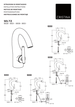
ARTLIFT
MONTAGEANLEITUNG ARTLIFT - HEBESITZ
ALHS0.
ASSEMBLY INSTRUCTIONS ARTLIFT - BATH LIFT
NOTICE DE MONTAGE ARTLIFT - SIÈGE RELEVABLE
MONTAGEVOORSCHRIFT ARTLIFT - Vloeroppervlak lift
ISTRUZIONI DI MONTAGGIO ARTLIFT - SEDILE SOLLEVABILE
MA_ArtL_11769_09_13
Vor Montage sorgfältig Lesen! Zum Nachschlagen und Aufbewahren dem Endkunden übergeben!
Read carefully before use! Hand over to the customer for looking up and storage!
Avant emploi lire soigneusement! Remettez le au client pour la recherche et le stockage!
Voordien gebruik zorgvuldig lezend! Overhandig de klant voor het kijken omhooggaand en opslag!
Prima dell‘uso con attenzione leggendo! cosegni il cliente per lo sguardo in su e l‘immagazzinaggio!
DEUTSCH
Originalsprache
ENGLISH
Translation
FRANCAIS
Traduction
1 / 24
NEDERLANDS
Vertaling
ITALIANO
Traduzione
ARTLIFT
INHALTSVERZEICHNIS
DE
OVERVIEW
VUE D’ENSEMBLE
OVERZICHT
SOMMARIO
Montageanleitung für Einbau LINKS - bei Einbau RECHTS - spiegelgleicher Aufbau.
Servicebereich, ..................................... 4
Hinweise, ............................................ 4
Montage.............................................11
»» Säule....................................................... 12
»» Sitz.......................................................... 15
Sicherheitshinweise................................ 5
»» Taster....................................................... 16
»» Strom.........................................................6
Stromanschluss herstellen...................... 17
»» Schutzbereiche.............................................7
»» Schaltplan...................................................8
Abdichten mit Sanitärsilikon ................... 22
Benötigtes Werkzeug............................... 9
Ersatzteile.......................................... 23
Montageset.......................................... 9
EN
Assembly instructions for installation LEFT - for installation RIGHT - assemble in mirror image.
Service area,........................................ 4
Note,.................................................. 4
Assembly............................................11
»» Post......................................................... 12
»» Seat......................................................... 15
Safety Instructions.................................. 5
»» Pushbutton................................................ 16
»» Electricity....................................................6
Connect power supply............................ 17
»» Protected areas.............................................7
»» Wiring diagramm...........................................8
Sealing with sanitary silicone.................. 22
Necessary tools..................................... 9
Spareparts......................................... 23
ASSEMBLYKIT....................................... 9
2 / 24
ARTLIFT
INHALTSVERZEICHNIS
FR
OVERVIEW
VUE D’ENSEMBLE
OVERZICHT
SOMMARIO
C’est prévue pour une installation à GAUCHE – en cas d’une installation à DROITE -A inverser pour partie fixe en GAUCHE.
Zone d‘entretien,.................................... 4
Attention,............................................. 4
Montage.............................................11
»» Colonne.................................................... 12
»» Siège....................................................... 15
Instructions de sécurité............................ 5
»» Capteur..................................................... 16
»» Courant.......................................................6
Etablir le raccordement électrique............. 17
»» Dèlimitations de protection..............................7
»» Plan de câblage............................................8
Etancher avec du silicone sanitaire ........... 22
Outillage necessaire............................... 9
Piéces de rechange............................... 23
SET DE MONTAGE................................... 9
NL
Montagevoorschrift voor inbouw LINKS - bij inbouw RECHTS - montage in spiegelbeeld.
Servicegebied,...................................... 4
Aanwijzing,.......................................... 4
Montage.............................................11
»» Steunpilaar................................................ 12
»» zitting....................................................... 15
Veiligheids Voorschriften.......................... 5
»» Knop........................................................ 16
»» Stroom.......................................................6
Elektriciteit aansluiten........................... 17
»» Veiligheids Zones..........................................7
»» Aansluitschema............................................8
Afdichten met sanitair-siliconen............... 22
Benodigd gereedschap............................. 9
Onderdelen......................................... 23
MONTAGESET....................................... 9
IT
Istruzioni di montaggio per la versione SINISTRA -all‘inverso per montaggio versione destra
Area assistenza,
Avviso
............................... 4
........................................... 4
Montaggio...........................................11
»» Montante................................................... 12
»» Sede........................................................ 15
Avviso di sicurezza................................. 5
»» Tasto........................................................ 16
»» Corrente......................................................6
Potere di fare...................................... 17
»» Zone di sicurezza...........................................7
»» Schema elettrico...........................................8
Sigillare con silicone per sanitari.............. 22
Attrezzature necessaria............................ 9
Pezzi di ricambio.................................. 23
CORREDO DELL‘ASSEMBLEA..................... 9
3 / 24
ARTLIFT
SERVICEBEREICH
SERVICE AREA
ZONE D‘ENTRETIEN
SERVICEGEBIED
AREA ASSISTENZA
ARTLIFT-Wanne & Vorrüstsatz
ARTLIFT-Tub & pre-fitting kit
ARTLIFT-Baignoire & Set de pré-équipement
ARTLIFT-Bad & Set t.b.v. voorbereidingen
ARTLIFT-Vasca & kit di installazione
60cm
HINWEIS
NOTE
ATTENTION
AANWIJZING
AVVISO
DE Mitgeltende Unterlagen: Abzw.rtliftDuschtür
Vormontageunterlagen 11768, Artlift Wanne 11771, Artlift Duschtür, Untertrittblenden 11773 und Seitenwand, Untertrittblenden 11772.
EN Applicable documents: Artlift
pre-installation documents 11768, Artlift Tub 11771, Artlift Shower door, plinth-panels 11773 bzw.Shower door and sidescreen, plinth-panels 11772.
FR Autres documentations: Artlift
le premontage documents 11768, Artlift Baignoire 11771, Artlift Porte de douche, les bandeaux 11773 bzw. Porte de douche et un panneau fixe, les bandeaux 11772.
NL Geldende documenten: Artlift
voormontagegegevens 11768, Artlift Bad 11771, Artlift Douchedeur, onderste panelen 11773 bzw. Douchedeur en 1 zijwand, onderste panelen 11772.
IT
Documenti applicabili:
Artlift Istruzioni Di Premontaggio 11768, Artlift Vasca 11771, Artlift Porta doccia, rivestimenti inferiori della vasca 11773 bzw. Porta doccia con laterale fisso, rivestimenti inferiori della vasca 11772.
4 / 24
ARTLIFT
SICHERHEITSHINWEISE
DE
•
•
•
•
safety
instructions
instructions
de sécurité
VEILIGHEIDS
VOORSCHRIFTEN
avviso di
sicurezza
Vor dem Einbau bitte unbedingt beachten!
Produkt vor dem Einbau, auf Richtigkeit, Beschädigungen und das Zubehör auf Vollständigkeit überprüfen.
Bei sichtbarem Schaden Produkt keinesfalls einbauen!
Beachten Sie beim Hantieren das teilweise hohe Gewicht und/oder die großen
Abmessungen von Einzelteilen
Beachten Sie beim Bohren der Löcher, dass Sie keine Leitungen
Elektro, Gas, Wasser) beschädigen.
Unsere Haftung beschränkt sich alleine auf unsere Produkte und kann daher nicht auf
den Ein- und Ausbau ausgedehnt werden. Die Kosten für einen nachträglichen Aus- und
Einbau eines Produkts und die damit verursachten Schäden sind kein Bestandteil der Garantie.
EN
•
•
•
•
Please note carefully before installing
Before installing, check for correctness and damage and the accessories for completeness.
Do not under any circumstances install product with visible damage!
Take the great weight and/or the large dimensions into consideration when handling individual parts!
When drilling holes do not damage hidden pipes and wiring.
Our liability is limited to our products alone and therefore cannot be extended to installation and dismantling. Costs for subsequent
dismantling and installation of a product and damage caused thereby are not part of the guarantee.
FR
•
•
•
•
A respecter impérativement avant le montage
Avant le montage de vérifier qu’il s’agit du bon modèle, qu’elle n’est pas endommagée et que les accessoires sont complets.
En cas de dommages visibles, ne pas monter le produit!
Lors de la manutention, merci de prêter attention au poids parfois très élevé et/ou aux dimensions de certaines pièces!
Faites attention en percant les trous de ne pas endommager les tuyauteries (cables électriques, canalisations
de gaz, d´eau, etc).
Notre responsabilité se limite à nos produits et ne peut être étendue sur l’installation et le démontage. Les coûts générés lors d’un démontage après installation et d’une ré-installation d’un produit et les dommages qui en résultent ne pourront être pris en charge par la garantie.
NL
•
•
•
•
Voor inbouw beslist in acht nemen!
Bad voor het inbouwen op juistheid, beschadigingen en toebehoren op volledigheid controleren.
Bij zichtbare beschadiging product in geen geval inbouwen!
Let u bij het gebruik om het gedeeltelijk grote gewicht en/of de grote afmetingen van enkele onderdelen!
bij het boren van gaten er op letten, dat U geen leidingen (elektro, gas of water) beschadigt!
Wanneer het bad betegeld wordt, beslist de inbouwmaten van de badkuip en van de doucheafscheidingin acht nemen.
Onze aansprakelijkheid is beperkt tot onze producten en kan daarom niet op de in- en uitbouw uitgebreid worden. De kosten voor een
latere uit- en inbouw van een product en de daaruit voortvloeiende schade zijn geen onderdeel van de garantie.
IT Osservazioni prima del montaggio!
•
•
•
•
Prima del montaggio controllare, se è la versione giusta, se ci sono difetti o se mancano pezzi.
Se ci sono dei difetti non montare la vasca.
Durante la fase di maneggio prestare attenzione al peso relativamente elevato e/o alle ampie dimensioni dei
singoli componenti!
Mentre forate fate attenzione a non rovinare le condutture (elettriche, gas, acqua).
La ditta ARTWEGER garantisce per il prodotto stesso e declina ogni responsabilità per il montaggio. Costi derivanti da smontaggio e
montaggio postumo ed eventuali danni causati non sono compresi nella garanzia.
5 / 24
ARTLIFT
DEDie Elektroinstallation darf nur von einem berechtigten Fachbetrieb unter Berücksichtigung der gesetzlichen Richtlinien sowie der na-
tionalen Errichtungsbestimmungen erfolgen (z.B.: Österreich EN 1-4 §49; Deutschland DIN VDE 0100-701 in der jeweils gültigen Ausgabe).
Leerrohr von oben bzw unten (mind. Ø 20 mm, Mindestverlegetiefe 5 cm). Separate Netzzuleitung H05-VV-F (flexible Leitung)
3x1,5 mm2 Absicherung 16A, über FI-Schutzschalter RCD ∆IN ≤ 30 mA. Zum Anschluss sollten ca. 3m Kabel vorgesehen werden. Gültige
Vorschriften für Potentialausgleich beachten! Potentialausgleichsleitung, 4 mm2 (Cu) für den Anschluss an die serienmäßige Erdungsklemme.
Die Leitung muß 2polig abschaltbar sein, mit min.3mm Kontaktöffnung (außerhalb von Schutzbereich 2) (z.b. Schütz geschalten über
Lichtschalter mit Kontrollanzeige)(Gemäß VDE 0100-701 bzw. ÖVE-EN 1 Teil 4, § 49).
EN Electrical installation may only be carried out by a qualified, registered company in compliance with legislation guidelines as well as
the currently valid edition of national installation regulations (e.g.; Austria EN 1-4 §49; Germany DIN VDE 0100-701).
Cable duct from above or below (min. 20 mm Ø, min. installation depth 5 cm). Separate mains supply line H05-VV-F (flexible line). 3 x
1.5 mm2 fuse protection 16A, over a RCD ∆IN ≤ 30 mA. For connection a cable of approx. 3 m should be provided. Take care to comply
with current regulations about potential equalization! Potential equalization line, 4 mm2 (Cu) for connection to the standard ground
terminal.
The line has to have a double-pole cut-off, with a min. 3 mm contact opening (outside of protected zone 2) (e.g. protection switched over
light switch with control indicator) (in accordance with VDE 0100-701 respectively ÖVE-EN 1 part 4, § 49).
FR L‘installation électrique ne peut être qu‘effectuée par une entreprise spécialisée sous la stricte observance des directives légales, ainsi que des
dispositions nationales liées à la construction (par ex.: Autriche EN 1-4 par.49; Allemagne DIN VDE 0100-701 respectivement dans sa dernière version).
Gaine à partir du haut ou bien du bas (diamètre minimum 20 mm, profondeur d‘encastrement minimum 5 cm). Alimentation réseau séparée
H05-VV-F (câble flexible) 3 x 1,5 mm2 protection 16A, par un interrupteur de sécurité FI RCD ∆IN ≤ 30 mA. Pour le raccordement il convient
de prévoir environ 3 m de câble. Respecter les directives en vigueur pour la compensation de potentiel ! Câble de compensation de potentiel,
4 mm2 (Cu) pour le raccordement à la borne de terre standard.
Le câble doit être muni d‘un dispositif d‘interruption bipolaire, avec une ouverture de contact de minimum 3 mm (en dehors de la zone de sécurité 2)
(par ex. contacteur branché sur interrupteur lumineux avec indication de contrôle) (Selon VDE 0100-701 ou bien ÖVE-EN Partie 4, paragraphe 49).
NL
De elektronische installatie mag slechts door een gespecialiseerd bedrijf, met inachtneming van de wettelijke richtlijnen en de nationale voorschriften betreffend de inbouw, worden uitgevoerd (bijv. Oostenrijk EN 1-4 §49, Duitsland DIN VDE 0100-701 in de betreffend geldige uitgave).
Losse buis van boven naar beneden (min. Ø 20 mm, minimale plaatsingsdiepte 5 cm). Aparte nettoevoerleiding H05-VV-F (flexibele leiding).
3x1,5 mm2 beveiliging 16A, via FI-veiligheidsschakelaar RCD ∆IN ≤ 30 mA Voor de aanleg moet tenminste rekening worden gehouden
met ca. 3m kabel. Let op de geldende eisen voor de potentiaalcompensatie! Leiding voor de potentiaalcompensatie 4 mm2 (Cu), voor de
aansluitingen aan de standaard aardklem.
De leiding moet 2-polig uitgeschakeld kunnen worden, met minimaal 3mm contactopening (buiten de beschermde sector 2). (Bijvoorbeeld veiligheidsschakelaar geschakeld via lichtschakelaar met controllampje.) (Volgens VDE 0100-701 resp. ÖVE-EN 1 deel 4, § 49).
IT
L‘installazione elettrica può essere effettuata solamente da una ditta specializzata autorizzata osservando le disposizioni di legge e i
regolamenti nazionali relativi all‘installazione (ad es. Austria: EN 1-4§49; Germania DIN VDE 0100-701 nelle edizioni in vigore). Canalina
dall‘alto e dal basso ( min. Ø 20 mm, profondità minima di posa 5 cm). Cavo di allacciamento alla rete separato H05-VV-F (Cavo flessibile).
Protezione da 3 x 1,5 mm2 16A, su interruttore di protezione FI RCD ∆IN ≤ 30 mA. Per l‘allacciamento si deve prevedere un cavo di ca. 3
mt. Prestare attenzione alle normative in vigore per il collegamento equipotenziale! Cavo di collegamento equipotenziale, 4 mm2 (Cu) per il
collegamento ai morsetti di messa a terra di serie.
Il cavo deve essere interrompibile a 2 poli, con un‘apertura di contatto di almeno 3 mm (ad eccezione dello spazio di protezione 2) (ad es.
protezione inserita su interruttore di luce con indicatore di controllo) (ai sensi del VDE 0100-701 e dell‘ ÖVE-EN 1 parte 4, § 49).
6 / 24
ARTLIFT
PROTECTED
AREAS
DÈLIMITATIONS DE
PROTECTION
VEILIGHEIDS
ZONES
ZONE DI
SICUREZZA
A
A-A
Zone 1
Zone 2
0,6 0m
Zone
60 cm
A
Schutzbereich 3
Protected area 3
Délimitation de protection 3
Zone 3
zona di sicurezza 3
cm
60
Schutzbereich 2
Protected area 2
Délimitation de protection 2
Zone2
Zona di sicurezza 2
60
cm
Schutzbereich 0/1
Protected area 0/1
Délimitation de protection 0/1
Zone 0/1
zona di sicurezza 0/1
Zone 1
DE
Die Schutzbereiche müssen zu Ihrer persönlichen Sicherheit genau eingehalten werden.
Schutzbereich 2:(Höhe 225 cm) Verbot von Schaltern und Steckdosen!
Die Schutzbereiche müssenzu Ihrer persönlichenSicherheit genau eingehalten werden.
Schutzbereich 2:(Höhe 225 cm) Verbot von Schaltern undSteckdosen!
DE
ENEN
For your personal safety, theprotected areas must be adhered to exactly.
For your
personal225
safety,
must be
adhered
to exactly.
Protected aera
2:(Height
cm) theprotected
No switchesareas
or power
outlets
allowed!
Protected aera 2:(Height 225 cm) No switches or power outlets allowed!
FR
Pour votre
propre
protection,lesdélimitations
délimitations de
de protections sont
à respecter
exactement.
FR
Pour votre
propre
sont
à respecter
exactement.
Délimitation
niveau
2 protection,les
:(Hauteur 225 cm)
Interdiction deprotections
poser des interrupteurs
ou des prises
de courant !
Délimitation niveau 2 :(Hauteur 225 cm) Interdiction de poser des interrupteurs ou des prises de courant !
NL
Voor uw persoonlijke veiligheidmoeten de veiligheidszones nauwkeurig worden aangehouden.
Veiligheidszone 2:(hoogte 225 cm) verbod op schakelaars en stopcontacten!
NL
Voor uw persoonlijke veiligheidmoeten de veiligheidszones nauwkeurig worden aangehouden.
Veiligheidszone 2:(hoogte 225 cm) verbod op schakelaars en stopcontacten!
IT
Per la propria sicurezza le zone di sicurezza devono essere rispettate.
Zona di sicurezza 2:(altezza 225 cm) vietato posizionare interruttori e prese elettriche!
IT
Per la propria sicurezza le zone di sicurezza devono essere rispettate.
Zona di sicurezza 2:(altezza 225 cm) vietato posizionare interruttori e prese elettriche!
7 / 24
225 cm
SCHUTZBEREICHE
ARTLIFT
SCHALTPLAN
WIRING
DIAGRAMM
PLAN DE
CÂBLAGE
AANSLUIT
SCHEMA
SCHEMA
elettrico
L
N
PE
FI- Schutzschalter IN 30 mA, FI circuit breaker IN 30 mA, Interrupteur de sécurité FI
FI- aardlekschakelaar IN 30 mA, salvavita RCD IN 30 mA.
IN 30 mA
Leitungs-Schutzschalter max. 16A, Automatic cutout 16A max., Interrupteur de sécurité courant max. 16A,
2-polige schakelaar max.16A, fusibile max. 16A.
Schütz, Contactor, Fusible, Zekering, Relais.
Hauptschalter mit Kontrolllampe im Bad, Main switch with control light in bathroom,
Interrupteur principal avec lampe de contrôle dans la salle de bain,
Hoofdschakelaar met controlelamp in de badkamer,
interruttore con luce di controllo nel bagno
Außerhalb des Schutzbereiches, Outside of protected area, En dehors de la délimitation de protection,
Buiten de veiligheidszone, al di fuori della zona di sicurezza
L
N
PE
8 / 24
Anschluss, Connection, Raccordement,
Aansluiting, Allacciamento.
ARTLIFT
BENÖTIGTES
WERKZEUG
NECESSARY
TOOLS
OUTILLAGE
NECESSAIRE
BENODIGD
GEREEDSCHAP
ATTREZZATURE
NECESSARIA
13
10 13
400 mm
MONTAGESET
ASSEMBLY
KIT
1x SW4
1x SW5
MatNr:11750
MatNr:1880
SET DE
MONTAGE
6x
MatNr:24437
1x 41,2x5,7mm
MatNr:18639
4x M4x12
MatNr:24377
4x M8x35
MatNr:24270
MONTAGE
SET
1x
2x M5x16
MatNr:24300
1x
MatNr:18807
3x M6x16mm
MatNr:24430
9 / 24
1x
MatNr:706638
6x
MatNr:706656
2x M8
MatNr:24316
4x M6x20
MatNr:24274
CORREDO
DELL‘ASSEMBLEA
1x
ARTLIFT
Vorrüstsatz
PREFITTING KIT
SET DE PRÉÉQUIPEMENT
SET T.B.V.
KIT DI
VOORBEREIDINGEN INSTALLAZIONE
a
b
DE
1. Rückenlehne, Untertritt und Schürzen entfernen.
2. Abdeckung der Wannendurchführung(a)
bzw. der Steuerung(b) abschrauben.
3. Ecksteher entfernen(c).
EN
1. Remove backrest, footboard
and skirting.
2. Unscrew the cover from the tub feedthrough (a) and the control (b).
3. Remove the corner support (c).
FR
1. Oter le dossier, le bandeau et
les tabliers
2. Dévisser le cache sur la zone aménagée dans la baignoire (a), ainsi que sur
l‘élément de pilotage (b).
3. Oter les supports d‘angle (c).
NL
1. Rugleuning, onderplint en
panelen verwijderen
2. Afdekking van de baddoorvoer (a) cq.
besturing (b) losschroeven.
3. Hoekpaal verwijderen (c).
c
IT
1. Rimuovere lo schienale, lo
zoccolo e la gonna.
2. Svitare la copertura del passante della
vasca (a) e l‘unità di comando (b).
3. Rimuovere il montante angolare (c).
10 / 24
ARTLIFT
1
SW 13
13
SW 13
11 / 24
180
170
170
160
170/180x80
160/170x75
ARTLIFT
2
Nicht verkratzen!
Do not scratch!
Ne pas rayer!
Maak geen krassen!
Non graffiare!
S.16
Ebener Bereich,
Flat area,
Partie plane,
Vlakke ondergrond,
Area piana.
SW5
1.
UP
UP
SW5
2.
innen
inside
intérieur
binnenkant
lato interno
4x
M8x35mm
2x M8
X
12 / 24
ARTLIFT
3
1.
50mm
3.
2.
4.
13 / 24
ARTLIFT
4
SW 13
3x
SW 13
M6x16mm
14 / 24
SW 10
10
ARTLIFT
5
1x
M8x30
4x
SW5
M6x20
15 / 24
ARTLIFT
6
1.
2.
4x
M4x12
3.
DE Stecker mit Steuerung verbinden
EN Connect plug to controller.
FR Raccoder la prise au le pilotage.
NL Stekker met besturing verbinden.
IT Collegare il connettore con l‘unità di comando.
16 / 24
ARTLIFT
7
DE Stromanschluss herstellen
EN Connect to electricity supply.
FR Réaliser le raccordement électrique.
NL Elektrische aansluiting tot stand brengen.
IT Potere di fare
L
N
PE
17 / 24
ARTLIFT
8
DE
1.Sitz hochfahren.
2.Kontrolle der Säule.
3.Ggf an den Stellfüssen justieren und
einrichten.
EN
1. Raise seat.
2. Check the post.
3. If necessary adjust the feet and level off.
FR
1.
1. Elever le siège en position haute
2. Contrôler la colonne.
3. Au besoin ajuster les pieds et mettre de
niveau.
NL
1. Zitje omhoog bewegen
2. Controle van de zuil
3. Eventueel aan de stelpoten aanpassen
en vastzetten
IT
1. Disporre il sedile in alto.
2. Controllare il montante.
3. Eventualmente, regolare
e mettere a punto
2.
SW 13
3.
3.
18 / 24
ARTLIFT
9
de1.Ecksteher einstzen
2.Steuerung mit Fussgestell verschrauben.
EN
1. Insert the corner support
2. Screw the control to the foot frame
Connect plug to controller.
FR
1. Positionner les supports
d‘angle.
2. Visser le pilotage avec le châssis de
pieds.
NL
1. hoekpaal plaatsen
2. besturing aan poten vastschroeven.
1.
IT
1 Installare il montante angolare
2. Avvitare l‘unità di comando alla base.
2.
2x
M5x20
19 / 24
ARTLIFT
10
A
B
1x
20 / 24
ARTLIFT
11
1.
2.
3.
KLICK
4.
SLOW
+
SW2
21 / 24
ARTLIFT
12
DE
NL
1.Schürzen einsetzen.
2.Untertritt-Blenden montieren.
1.Schorten inzetten.
2.Onderste panelen monteren.
EN
1.Insert skirts.
2.Insert plinth-panels.
1.Montare i rivestimenti.
2.Montaggio del rivestimento inferiore della vasca.
IT
FR
1.Poser tabliers.
2.Posez les bandeaux.
22 / 24
ESRSATZTEILE
SPARE
PARTS
PIÈCES DE
RECHANGE
23 / 24
ONDER
DELEN
PEZZI DI
ARTLIFT
RICAMBIO
ARTLIFT
Artweger GmbH. & Co. KG
Sulzbacherstraße 60 | 4820 Bad Ischl | Austria
Tel. +43 6132 205-0 | Fax +43 6132 25034
[email protected] | www.artweger.at
Niederlassung Wien
Goldschlagstraße 178 | 1140 Wien | Austria
Tel. Schauraum +43 1 9142753-11
Tel. Auftragsabwicklung +43 6132 205-25
Fax +43 1 9142753-22
[email protected]
Verkauf Deutschland
Artweger GmbH. & Co. KG
Postfach 1169 | 83402 Ainring | Deutschland
Tel. 0800 1114442-0 | Fax 0800 1114442-41
[email protected] | www.artweger.de
Verkauf Schweiz
Druck- und Satzfehler sowie technische Änderungen vorbehalten.
Typographical errors and technical changes reserved.
Sous réserve d‘erreurs d‘impression ou de syntaxe ainsi que de modifications techniques.
Drukfouten, maatwijzingen en technische veranderungen voorbehouden.
Ci riserviamo errori di stampa e variazioni tecniche.
24 / 24
3/3
MA_ArtL_11769_09_13
Artweger GmbH. & Co. KG
Postfach 16 | CH-4202 Duggingen
Tel. + 41 61 751 90 91
[email protected] | www.artweger.com
Scarica