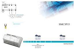
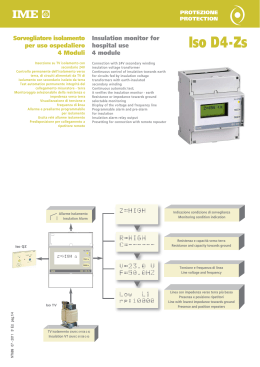
SORVEGLIATORE DI ISOLAMENTO PER USO OSPEDALIERO
INSULATION MONITORING FOR HOSPITAL USE
NT492 07 - 2004 5a Edizione / Edition pg.1/2
96x96 DIN 43700
Controllo permanente dell’isolamento verso terra, di circuiti alimentati da TV
di isolamento con secondario isolato da terra
Test automatico permanente integrità del collegamento misuratore – TV
isolamento - nodo equipotenziale
Visualizzazione livello resistenza di isolamento 25kΩ…1MΩ
Soglia intervento regolabile 50…500kΩ
1 contatto di allarme (optorelè 110Vcc/ca 50mA)
Uscita per quadretto segnalazione ripetitore remoto ARI1
RI2H3
Continuous control of insulation towards earth for circuits fed by isolation
transformers with earth-insulated secondary winding
Continuous automatic test: it verifies the insulation monitor – isolation
transformer - equipotential junction connection
Insulation resistance level display 25kΩ…1MΩ
Selectable threshold 50…500kΩ
1 alarm output (optorelay 110Vdc/ac 50mA)
Signal output for remote repeater panel ARI1
INGRESSO
INPUT
Inserzione: circuiti alimentati da TV/230V di isolamento con secondario isolato da
Connection: circuits fed by isolation transformer /230V with earth-insulated
terra
secondary winding
Tensione di linea: 230 e 240Vca
Network voltage: 230 and 240Vac
Frequenza nominale fn: 50Hz
Rated frequency fn: 50Hz
Frequenza di funzionamento: 47…63Hz
Working frequency: 47…63Hz
Tensione di misura : 12Vcc
Metering voltage: 12Vdc
Corrente di misura: ≤ 0,2mA
Metering current: ≤ 0,2mA
PREDISPOSIZIONE
SETTING UP
Punto di intervento: regolabile con commutatore rotativo 6 posizioni
Intervention point: selectable by 6-position rotary switch
Portate: 50 / 70 / 100 / 150 / 300 / 500kΩ
Ranges: 50 / 70 / 100 / 150 / 300 / 500kΩ
Tempo di intervento: ≤ 0,5 secondi
Intervention time: ≤ 0,5 seconds
Precisione intervento: ± 10% del valore selezionato
Accuracy: ± 10% setting value
SEGNALAZIONE
SIGNALING
Strumento alimentato: LED verde “ON”
Power ON: green LED “ON”
Intervento allarme: LED rosso “ALARM” + commutazione relè
Alarm intervention: red LED “ALARM” + relay switching
Interruzione collegamento: LED rosso “ALARM”, LED rosso “FAIL” +
Connection failure: red LED “ALARM”, red LED “FAIL” + switching relay
commutazione relè
CONTROLLO
CONTROL
Test manuale: verifica l’efficienza del dispositivo
Manual test: it verifies the device perfect working
Test automatico permanente: verifica l’integrità dei collegamenti del misuratore al
Continuous automatic test: it verifies the insulation monitor – isolation transformer
TV di isolamento e al nodo equipotenziale
- equipotential junction connection
ALLARME
ALARM
Riarmo (reset): automatico
Reset: automatic
Isteresi (intervento – ripristino): ≤ 5%
Hysteresis (intervention – reset): ≤ 5%
USCITE
OUTPUT
ALLARME
ALARM
Optorelè “ALARM”: 1 contatto SPST
Optorelay “ALARM”: 1 SPST contact
Portata contatti: 110Vcc/ca 50mA
Contact range: 110Vdc/ac 50mA
Sicurezza: negativa (relè normalmente diseccitato)
Security: negative (normally de-energised relay)
QUADRETTO RIPETITORE REMOTO ARI1
REMOTE REPEATER PANEL ARI1
Uscita per quadretto ripetitore remoto, isolata da alimentazione misuratore e linea
Output for remote repeater panel, insulated from insulation monitor supply and
monitorata
network
Ad ogni sorvegliatore di isolamento RI2H3 possono essere collegati fino a 5
Each insulation monitor RI2H3 can supply up to 5 repeater ARI1
Protezione contro eventuale corto circuito sui collegamenti misuratore – quadretto
Protection against possible short circuit insulation monitor - remote repeater panel
ripetitore
connection
ALIMENTAZIONE AUSILIARIA
AUXILIARY SUPPLY
Valore nominale Uaux: 230 e 240V
Rated value Uaux: 230 and 240V
Variazione ammessa: 0,9…1,1Uaux
Tolerance: 0,9…1,1Uaux
Frequenza nominale: 50Hz
Rated frequency: 50Hz
Variazione ammessa: 47…63Hz
Tolerance: 47…63Hz
Autoconsumo: ≤ 4VA
Rated burden: ≤ 4VA
(EN60439-1, EN61010-1)
INSULATION
(EN60439-1, EN61010-1)
Categoria di installazione: III
Installation category: III
Grado di inquinamento: 2
Pollution degree: 2
Tensione di riferimento per l’isolamento: 600V
Insulation reference voltage: 600V
Prova di tensione a impulso 5kV 1,2/50µs 0,5J
Impulse voltage test 5kV 1,2/50µs 0,5J
Circuiti considerati: ingresso, relè, alimentazione ausiliaria
Considered circuits: input, relay, aux. supply
Prova a tensione alternata 4kV valore efficace 50Hz/1min
A.C. voltage test 4kV r.m.s. 50Hz/1min
Circuiti considerati: ingresso, relè, al. ausiliaria
Considered circuits: input, relay, aux. supply
Prova a tensione alternata 4kV valore efficace 50Hz/1min
A.C. voltage test 4kV r.m.s. 50Hz/1min
Circuiti considerati: tutti i circuiti e massa
Considered circuits: all circuits and earth
PROVE DI COMPATIBILITÀ’ ELETTROMAGNETICA
(EMC)
TESTS FOR ELECTROMAGNETIC COMPATIBILITY
Prove di emissione in accordo con EN50081, EN55011
Emission tests acording to EN50081, EN55011
Prove di immunità in accordo con EN50082-2
Immunity tests according to EN50082-2
CONDIZIONI AMBIENTALI
(EN 60255-6)
ENVIRONMENTAL CONDITIONS
Temperatura di riferimento: 20°C ± 2°C
Reference temperature: 20°C ± 2°C
Temperatura di impiego: - 5…40°C
Nominal temperature range: -5…40°C
Temperatura limite di funzionamento: -10…55°C
Limit temperature range: -10…55°C
Temperatura di magazzinaggio: - 25…70°C
Limit temperature range to storage: -25…70°C
Umidità relativa: 45…75%
Relative humidity: 45…75%
Adatto all’utilizzo in clima tropicale
Suitable for tropical climates
Massima potenza dissipata : ≤ 3,5W
Max. power dissipation1: ≤ 3,5W
1
1
Per il dimensionamento termico dei quadri
1
(EN60255-6)
For switchboard thermal calculation
CUSTODIA
HOUSING
Fissaggio: incasso (foratura pannello 92x92mm)
Housing: flush mounting (panel cutout 92x92mm)
Frontale: 96x96mm DIN43700
Front frame: 96x96mm DIN43700
Profondità: 103mm
Depth: 103mm
Connessioni: morsetti fissaggio a vite per conduttore fino a 2,5mm
Connections: screw terminals for cable up to 2,5mm 2
Materiale custodia: makrolon autoestinguente
Housing material: self-extinguishing makrolon
Grado di protezione (EN60529): IP40 frontale, IP20 morsetti
Protection degree (EN60529): IP40 front frame, IP20 terminals
Peso: 680 grammi
Weight: 680 grams
2
SCHEMA D’INSERZIONE
S 291/89
WIRING DIAGRAM
DIMENSIONI
21
INPUT
14 15
10 11
OUTPUT
2
1
ARI1(option)
5
6 8
9
6
5
1
2
7
99
1
2
PE
L
115V
230V
115V
5,5
8
99 96
92
N
DIMENSIONS
RI2H3
AUX. SUPPLY
20
(EMC)
92
91x91
96
22
81
11
NT492 07 - 2004 5a Edizione / Edition pg.2/2
ISOLAMENTO
La I.M.E. S.p.A. si riserva in qualsiasi momento, di modificare le caratteristiche tecniche senza darne preavviso. / I.M.E. S.p.A. reserves the right, to modify the technical characteristics without notice.
ripetitori ARI1
Scaricare