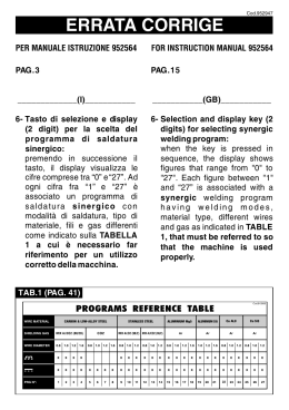
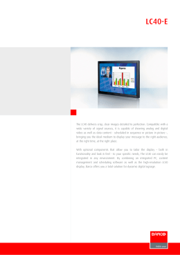
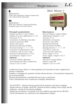
LIBRETTO
LIBRETTO USO
USO EE MANUTENZIONE
MANUTENZIONE
USE
USE AND
AND MAINTENANCE
MAINTENANCE MANUAL
MANUAL
FORNO
FORNO PER
PER CILINDRI
CILINDRI
PRE-HEATING
PRE-HEATING FURNACE
FURNACE
DAKO
DAKO 5240-5250
5240-5250
DAKO 5240-5250
The Manufacturer reserves the right to modify the technical and functional features of the appliances described in this instruction manual without giving prior notice;
also, will not answer for any inaccuracies, attributable to printing or transcription errors, in this instruction manual.
Il Costruttore si riserva il diritto di apportare modifiche alle caratteristiche tecniche e funzionali dei prodotti presentati in questa pubblicazione senza dare alcun preavviso;
inoltre, non risponde di possibili inesattezze, imputabili ad errori di stampa o di trascrizione, contenute nel presente libretto.
2
DAKO 5240-5250
Indice / Index
ITALIANO
SCOPO DELL’ APPARECCHIO ........................................................................................................................................................ pag.4
PRECAUZIONI ................................................................................................................................................................................. pag.4
INSTALLAZIONE .............................................................................................................................................................................. pag.4
ATTIVAZIONE ................................................................................................................................................................................... pag.4
ACCENSIONE .................................................................................................................................................................................. pag.4
PROGRAMMAZIONE ....................................................................................................................................................................... pag.4
Creazione di un programma .................................................................................................................................................... pag.4
Modifica di un programma esistente ....................................................................................................................................... pag.5
ESECUZIONE DI UN PROGRAMMA ............................................................................................................................................... pag.5
Modalità “FAST” ...................................................................................................................................................................... pag.6
Richiesta del tempo mancante ................................................................................................................................................ pag.6
INTERRUZIONE DI UN PROGRAMMA ........................................................................................................................................... pag.6
MANCANZA DI TENSIONE .............................................................................................................................................................. pag.6
AUTODIAGNOSTICA ....................................................................................................................................................................... pag.6
GARANZIA ........................................................................................................................................................................................ pag.6
Certificato di Garanzia su modello UNIDI-ANCAD ........................................................................................................................... pag.7
Regolamento ..................................................................................................................................................................................... pag.7
ENGLISH
SCOPE OF THE DEVICE ................................................................................................................................................................. pag.8
PRECAUTIONS ................................................................................................................................................................................ pag.8
INSTALLATION ................................................................................................................................................................................. pag.8
POWER-UP ...................................................................................................................................................................................... pag.8
START-UP ......................................................................................................................................................................................... pag.8
PROGRAMMING .............................................................................................................................................................................. pag.8
How to make a program .......................................................................................................................................................... pag.8
How to change an existing program ........................................................................................................................................ pag.9
EXECUTION OF A PROGRAM ........................................................................................................................................................ pag.9
“FAST” Mode ........................................................................................................................................................................... pag.10
Request for residual time ........................................................................................................................................................ pag.10
INTERRUPTION OF A PROGRAM .................................................................................................................................................. pag.10
MAIN VOLTAGE FAILURE ................................................................................................................................................................ pag.10
SELF-TEST ....................................................................................................................................................................................... pag.10
WARRANTY ...................................................................................................................................................................................... pag.11
Certificate of garantee (approved by UNIDI) ..................................................................................................................................... pag.11
Guarantee regulations ...................................................................................................................................................................... pag.11
RICAMBI / SPARE PARTS. ................................................................................................................................................... pag.12
DICHIARAZIONE DI CONFORMITÁ / DECLARATION OF CONFORMITY. ..................................................... pag.19
3
DAKO 5240-5250
DAKO 5240-5250
Il presente manuale delle istruzioni d’uso è parte integrante della fornitura dell’apparecchiatura e deve accompagnare la stessa in ogni trasferimento.
Il manuale va conservato con cura per tutto il ciclo di
vita dell’apparecchio ed essere comunque reperibile per
almeno 10 anni. Esso va conservato in luogo noto e
reso disponibile a tutte le persone interessate.
Non collegare o mettere in funzione l’apparecchio prima di aver letto questo manuale.
ATTIVAZIONE
4
SOAK
•
Installare l’apparecchio su di una superficie piana e stabile in grado di sopportarne il peso.
Prestare attenzione a:
•
non immergere il cavo di alimentazione in acqua
tenere il cavo di alimentazione lontano da fonti di
calore
non lasciare pendere il cavo di alimentazione da bordi
di mobili
•
Prima di proseguire verificare che:
• il cavo di alimentazione o la spina non siano danneggiati.
• l’apparecchio non si presenti danneggiato
hr:min
Il collegamento alla terra è obbligatorio a norma di legge. L’installazione va eseguita da un installatore qualificato che possa assicurarsi di tale adempimento.
Il fabbricante declina ogni responsabilità per eventuali danni a caose o a persone derivanti dalla mancata ossservanza dei punti precedenti.
•
INSTALLAZIONE
Il forno si accende per mezzo dell’interruttore generale posto sul fianco deìstro della base del forno stesso.
Accendendo il forno si illumina il display “prog” (1).
PROGRAMMAZIONE
La programmazione del forno può iniziare solo quando
il forno è in stato di riposo, in tale stato solo i display
program e soaks possono essere acccesi.
Nel caso non siano ancora stati immessi programmi sul
display program apparirà il numero “0” lampeggiante;
altrimenti comparirà il numero dell’ultimo programma
utilizzato acceso in modo fisso. In quest’ultimo caso sul
display SOAKS (4) apparirà anche il numero di stasi di
cui è composto il programma.
CREAZIONE DI UN PROGRAMMA
Con il forno in condizioni di riposo per mezzo dei tasti
e/o
selezionare il numero di programma sul display program.
premere il tasto FUNC
a) Selezione numero di stasi
Il display SOAKS lampeggia indicando il numero “9”
scegliere per mezzo dei tasti e/o il numero di stasi
di cui il programma sarà costituito (da 1 a 9)
premere FUNC
b) Programmazione del tempo di attesa
4
FAN
FAST
Inserire la spina dell’apparecchio in una presa adatta per tensione e potenza ai dati riportati sulla targa
dell’apparecchioe munita di terra.
•
•
°C
WAIT R1 S1 R2 S2 R3 S3 R4 S4 R5 S5 R6 S6 R7 S7 R8 S8 R9 S9
ACCENSIONE
•
3
°F
PRECAUZIONI
Alcuni materiali utilizzati per la confezione dei
preformati, da soli o unitamente ad altri componenti
del rivestimento, possono generare dei vapori ad
altissima reattività chimica nei confronti delle leghe
che costuituiscono le resistenze di riscaldo.
E’ sempre ottima cosa provvedere all’estrazione della
cera mediante essiccatore od un forno a gas in modo
da introdurre nel forno elettrico i cilindri già privati
delle sostanze chimiche più attive.
Assicurarsi che l’impianto elettrico sia dotato di dispositivo salvavita
2
PROG
SCOPO DELL’APPARECCHIO
I forni DAKO 5240-5250 servono per il preriscaldo dei
cilindri, confezionati con qualsiasi tipo di rivestimento
utilizzato nei laboratori odontotecnici.
Entrambi i forni DAKO, possono essere dotati di aspiratori per l’estrazione dei fumi dalla camera di riscaldo;
il funzionamento degli, può essere controllato direttamente dal pannello di controllo. Qualsiasi utilizzo diverso da quanto sopra descritto è da considerarsi improprio e libera il costruttore da ogni responsabilità riguardo a danni di qualsiasi natura, facendo inoltre decadere i diritti di garanzia sull’apparecchio stesso.
1
L’indicatore “WAIT” lampeggia mentre il display (3)
visualizza 00.00. Selezionare la durata dell’attesa in
ore e minuti (hh:mm) tra 0 e 99:99.
premere FUNC
c) Programmazione dell’aspiratore
I forni DAKO 5240-5250 possono essere dotati di aspiratore in tal caso occorre programmarne il funzionamento ne modo descritto nel seguito.
Lampeggia l’indicatore R1 mentre i display () e ()
visualizzano rispettivamente le scritte “ON” e “FAN”
entrambe lampeggianti
I tasti e permettono di scegliere tra “ON” e “OFF”.
Impostando “ON” l’aspiratore rimarra inserito per il tempo necessario a raggiungere la temperatura da stabilizzare e per tutta la durata della stabilizzazione della
stessa.
g) Programmazione dell’allarme
E’ acceso in modo fisso l’indicatore S dell’ultima stasi il
display (3) mostra la scritta “AL” ed il display (2) la scritta “ON”.
I tasti e permettono di scegliere tra “ON” e “OFF”.
Impostando “ON” si avrà l’allarme acustico, con “OFF”
invece sarà disinserito.
Premere FUNC
h) Visualizzazione della durata complessiva del
programma
Il display (3) visualizza ora la durata del programma
calcolata in base ai parametri immessi. Nel caso siano
stati immessi uno o più gradienti “dir”, vista l’impossibilità del calcolo verrà visualizzata la scritta “dir”.
Premere FUNC
Premere FUNC
A questo punto il programma viene memorizzato
d) Programmazione della velocità di salita della temperatura, in °C/minuto. Questo parametro sarà indicato
nel seguito come gradiente.
L’indicatore R1 continua a lampeggiare mentre il display
(2) indica “1”
e
il gradiente desiScegliere per mezzo dei tasti
derato. Il massimo valore numerico selezionabile è 13
°C/minuto, oltre questo valore compare la scritta “dir”,
selzionando quest’ultimo valore il riscaldamento non
sarà più controllato e sarà il più veloce possibile.
MODIFICA DI UN PROGRAMMA ESISTENTE
Per modificare un programma già esistente procedere
come descritto in precedenza per la creazione di un programma tranne che per i punti seguenti:
Alla prima pressione del tasto FUNC viene visualizzata
sul display (3) la durata complessiva del programma
calcolata secondo i parametri attuali
Sui display compaiono i valori immessi, anzichè quelli
di inizializzazione.
Premere FUNC
e) Programmazione della temperatura da stabilizzare in °C
Lampeggia l’indicatore S1 mentre il display (2) mostra
il valore “0”
e
selezionare la temperatura
per mezzo dei tasti
che si vuole stabilizzare.
La temperatura massima selezionabiile è 1100°C.
Premere FUNC
f) Programmazione del tempo di stabilizzazione
L’indicatore S1 continua a lampeggiare mentre il display
(3) mostra il valore 00:00.
e/o
selezionare il tempo di
per mezzo dei tasti
stabilizzazione in ore e minuti della temperatura impostata al passo precedente.
Premere FUNC
Se si sono scelte più stasi i passi precedenti andranno
ripetuti tante volte quante sono le stasi selezionate.
Giunti all’ultima stasi occorrerà programmare l’allarme
ESECUZIONE DI UN PROGRAMMA
Con il forno in stato di riposo selezionare sul display (1)
il programma che si vuole eseguire con i tasti D—. Il
numero del programma deve essere acceso in modo
fisso.
Premere il taso RUN/ABORT
a)Se il programma selezionato prevede un tempo di
attessa si accende l’indicatore “WAIT” ed il display (3)
mostra il tempo che manca alla fine dell’attesa. Sul display (2) è visualizzata la temperatura della camera.
Durante questa fase il forno non riscalda.
b)Terminata l’eventuale attesa si accende l’indicatore
R1 ed il forno inizia a riscaldare. Nel caso si sia programmato l’intervento dell’aspiratore, esso inizia a funzionare.
Il display (2) mostra la temperatura della camera
c)Quando la temperatura da stabilizzare viene raggiunta si accende l’indicatore S1, sul display (3) viene mostrato il tempo che manca alla fine della stasi, il display
(2) mostra la temperatura della camera.
5
ITALIANO
DAKO 5240-5250
DAKO 5240-5250
I punti b) e c) si ripetono per tutte le stasi previste, a
questo punto il programma termina e sul display (2)
compare la scritta “End”.
Nel caso sia stato programmato l’avvisatore acustico
questo entra in funzione.
L’avvisatore acustico suonera per dieci secondi, quindi
vi sarà un intervallo di diue minuti, il ciclo si ripeterà per
cinque volte poi l’avvisatore acusticco verrà disinserito.
Contemporaneamente al suono si accendera l’indicatore con il simbolo della campana.
La temperatura programmata per l’ultima stabilizzazione verrà mantenuta indefinitamente.
N.B.:
Se durante il riscaldamento si apre lo sportello del forno, sul display (2) comparirà la scritta “open”
MODALITÀ “FAST”
Durante l’esecuzione di un programma è possibile non
eseguire alcuni passi del programma stesso eseguendo regolarmente quelli successivi. per effettuare questa operazione procedere nel seguente modo:
premere contemporaneamente il tasto RUN/ABORT ed
il tasto D, l’indicatore “FAST”comincia a lampeggiare.
Tramite il tasto D si seleziona il passo del programma,
successivo a quello in esecuzione, che si vuole eseguire.
Premerre di nuovo RUN/ABORT per conferma; l’indicatore “FAST” rimane acceso ed il forno raggiungerà il
più velocemente possibile la temperatura programmata per il punto selezionato. Una volta raggiuntala l’indicatore “FAST” si spegnerà ed il programma proseguirà
regolarmente.
RICHIESTA DEL TEMPO MANCANTE
Durante una stasi è possibile visualizzare il tempo che
manca alla fine del programma premendo contempoe/o .
raneamente oi tasti
Il tempo rimarra visualizzato fintanto che verranno premuti i tasti.
Nel caso nel programma sia presente un gradiente “dir”,
verrà visualizzata la scritta “dir”
INTERRUZIONE DI UN PROGRAMMA
Per interrompere un programma in esecuzione premere il tasto RUN/ABORT per almeno cinque secondi. Rimarranno accesi il display con il numero del programma e quello con il numero delle stasi. Gli indicatori “wait”,
S, R si spegneranno.
non vi sono variazioni di temperatura ed il processo
prosegue regolarmente.
b) Se l’interruzione è più lunga in modo da comportare
una diminuzione sensibile di temperatura il forno si comporterà nel seguente modo:
Se la temperatura è variata meno di cinque gradi, il programma ripartirà dal punto memorizzato al momento
dell’interruzione
Se la temperatura è variata per più di cinque gradi, il
forno attenderà che sia nuovamente raggiunta la temperatura memorizzata al momento dell’interruzione per
proseguire.
AUTODIAGNOSTICA
Alcune situazioni anomale o guasti vengono segnalati
sui display sotto forma di codici di errore o scritte.
Codici di errore
gli errori vengono segnalati tramite un codice sul display superire e la scritta “Err” su quello inferiore.
I codici sono i seguenti:
001
002
003
004
005
200
202
203: la durata totale del programma è superiore ai limiti di visualizzazione, pertanto il programma non viene
memorizzato
204: non è più possibile controllare la temperatura
206: termocoppia interrotta
“open”: sportello aperto o resistenze interrotte
L’errore 202 consente la prosecuzione del programma
premendo il tasto D.
Gli altri codici di errore interrompono il programma in
esecuzione.
GARANZIA
L’apparecchio è garantito 12 mesi
La garanzia decade in caso di uso improprio, manomissione o utilizzo di ricambi non originali.
MANCANZA DI TENSIONE
a)Interruzioni istantanee,
Il consumo viene ridotto al minimo spegnendo i display
ed interrompendo il riscaldamento. al ritorno dell’alimentazione, dato il tempo estremamente breve dell’interruzione,
6
La mancata restituzione del Certificato di Garanzia,
implica l’immediata decadenza della medesima.
La garanzia non copre le spese di manodopera e trasferta, che saranno sempre e comunque a carico dell’acquirente
Certificato di Garanzia su modello UNIDI-ANCAD
1. Col presente documento il fabbricante certifica la corretta costruzione del prodotto, l’impiego di materiali
di prima qualità, l’effettuazione di tutti i collaudi necessari e la sua aderenza alle norme vigenti. Il prodotto è coperto da un periodo di Garanzia di mesi
12 dalla data di consegna all’utente, che dovrà essere comprovata dalla restituzione dell’allegato tagliando controfirmato dall’Utente.
La garanzia è limitata alla sostituzione o sistemazione delle singole parti o dei pezzi che risultano di
fabbricazione difettosa, con esclusione delle spese
di manodopera, trasferta del personale tecnico, spese di trasporto, di imballaggio, ecc.
Sono esclusi dalla Garanzia guasti o danni derivanti
da cattiva manutenzione, da scorretta alimentazione, negligenza, imperizia o cause non imputabili al
fabbricante.
Sono da escludersi dalla Garanzia le avarie causate da mancata manutenzione ordinaria dovuta a trascuratezza dell’utilizzatore.
La presente Garanzia non comporta alcun risarcimento di danni diretti o indiretti di qualsiasi natura
verso persone o cose, dovuti all’eventuale inefficienza dell’apparecchiatura.
2. La Garanzia decade automaticamente qualora le
apparecchiature vengano riparate, modificate o comunque manomesse dall’acquirente o da terzi non
autorizzati.
3. Per gli interventi in Garanzia l’acquirente dovrà rivolgersi unicamente al venditore, oppure ai centri di
assistenza indicati dal fabbricante o al produttore
stesso.
La Garanzia dà diritto alla sostituzione gratuita della
parte difettosa. É comunque escluso il diritto alla sostituzione dell’intero apparecchio.
4. Nel caso di contestazione sull’applicazione della Garanzia, sulla qualità o sulle condizioni delle
apparecchiature consegnate, l’acquirente non potrà
sospendere o ritardare il pagamento del prezzo o
delle rate di prezzo.
5. Nessun risarcimento potrà essere richiesto dall’acquirente per fermo delle apparecchiature.
6. La Garanzia decade se:
a) l’apparecchiatura presenta danneggiamenti provocati da caduta, da esposizioni a fiamme, da rovesciamenti di liquidi, da fulmini, da calamità naturali,
o comunque da cause non imputabili a difetti di fabbricazione;
b) non vi è stata una corretta installazione;
c) vi è stato collegamento alla rete (tensione nominale di alimentazione errata);
d) il numero di matricola risulti asportato, cancellato
o alterato.
7. I componenti da sostituirsi in garanzia, devono essere restituiti alla Casa che ha provveduto o provvederà alla spedizione del ricambio. Qualora il pezzo
cambiato non venga restituito, verrà addebitato all’ordinante.
8. Per ragioni fiscali le parti di ricambio verranno
concesse in garanzia unicamente nel caso in cui
ci sia pervenuto il tagliando di garanzia contenente tutti i dati relativi al cliente.
Regolamento
1. La mancata restituzione del Certificato di Garanzia
implica l’immediata decadenza della medesima.
La Garanzia non copre le spese di manodopera e
trasferta che saranno sempre e comunque a carico
dell’acquirente.
2. Il pagamento delle fatture di manodopera, trasferta
e diritto di chiamata, dovrà avvenire a presentazione delle medesime. Il mancato pagamento implicherà l’automatico decadimento della Garanzia.
3. Il fabbricante nonché il Deposito Dentale non sono
tenuti a dare in uso apparecchiature sostitutive per
il periodo di riparazione.
4. Per ogni altro caso non contemplato dal presente
Certificato di Garanzia e dal regolamento si fa riferimento alle norme del Codice Civile.
Legge 31 dicembre 1996, n. 675
I Clienti sono informati, ai sensi dell’art. 10 della Legge
31 dicembre 1996, n. 675, e pertanto approvano espressamente che i dati forniti per l’attivazione delle clausole
di garanzia possono essere trattati da SARATOGA
S.p.a., con sede legale in Pordenone, per:
a) l’adempimento degli obblighi previsti da leggi, regolamenti e dalla normativa comunitaria, ovvero da disposizioni impartite da autorità a ciò legittimate dalla legge, nonché da organi di vigilanza;
b) finalità strettamente connesse e strumentali all’esecuzione ed alla gestione del contratto con Lei/Voi
stipulato;
c) finalità gestionali, statistiche, commerciali, di
marketing e promozionali.
Il conferimento dei dati personali di cui alla lett. a) è
obbligatorio ed il rifiuto di fornirli determinerà l’impossibilità dell’instaurazione e/o della prosecuzione
del rapporto commerciale. Il conferimento dei dati
personali di cui alla lett. b) non è obbligatorio, ma il
rifiuto di fornirlo determinerà l’impossibilità
dell’instaurazione e/o della prosecuzione del contratto con Lei/Voi concluso, nonché delle operazioni
di revisione e riparazione relative alla fornitura alla
quale il contratto si riferisce. Il conferimento dei dati
di cui al punto c) non è obbligatorio, ma il rifiuto di
fornirli determinerà l’impossibilità per Lei/Voi di fruire di iniziative commerciali della Società, nonché di
essere destinatario di materiale promozionale della
medesima.
Il trattamento per le finalità di cui alle lett. a) e b) e c)
non richiede il consenso, ai sensi dell’art. 12, comma
1, lett. a) e b) L. 675/96.
7
ITALIANO
DAKO 5240-5250
DAKO 5240-5250
DAKO 5240-5250
This User’s Manual forms integral part of the delivered
equipment and it must always accompany it on each
transfer.
The User’s Manual has to be carefully preserved during
the whole lifetime of the concerned device and it must
be held within reach for at least 10 years. The place
where it is kept must be familiar to the personnel and at
hand to all the involved people.
Avoid connecting or starting the device in question
without this Manual has been previously read.
POWER-UP
4
1
2
3
PROG
°C
°F
SOAK
FAN
FAST
hr:min
WAIT R1 S1 R2 S2 R3 S3 R4 S4 R5 S5 R6 S6 R7 S7 R8 S8 R9 S9
SCOPE OF THE DEVICE
The furnaces DAKO 5240-5250 are intended for
preheating the flasks, coated with any kind of covering
as used in the dental mechanics laboratories.
Both DAKO furnaces may be equipped with exhaust
fans in order to remove the fumes from the heating
chamber; their operation may be controlled directly
through the control panel. Any use other than described
above has to be considered an improper use, which
relieves the manufacturer of any responsibility for
damages of any kind whatever, furthermore involving
the user's forfeiture of any right of guarantee covering
the device.
•
PRECAUTIONS
START-UP
•
•
Some ones of the materials used for pre-forming,
either alone or in conjunction with other components
of the coating, may release vapours with highest
chemical reactivity, which strongly react the alloys
with whom are made the heating resistors.
It is recommended to remove the wax by means of a
drier or a gas furnace so that the flasks taken into
the electric furnace are already free from the most
active chemical substances.
Make sure the electric system is equipped with safety
cutout.
•
•
INSTALLATION
Install the device on a flat surface, suitable to bear its
weight.
The following precautions should be taken:
• Avoid immersing the power cable into the water and
keeping the cable far from heat sources.
• Avoid the power cable hangs down from the edges
of the furniture.
Before going on, check that:
• The power cable and plug are not damaged.
• The device is in full working order (no visible
damages)
8
Plug the device in a socket having voltage and power
ratings corresponding to the rated output of the
device, and fitted with protective earthing.
Grounding is mandatory by the operation of Law.
The installation has to be carried out by a skilled installer, qualified to inspect the above mentioned
provision is fulfilled. The manufacturer declines
all responsibility for any injury to people or
damages to things possibly arising from the
non-compliance with the above-mentioned
rules.
Switch on the furnace by means of the main switch,
placed on the right side of the furnace base. When
the furnace is started, the “prog” display (1) turns
on.
PROGRAMMING
The furnace programming may start only when the
furnace is idle; under this condition, the Program and
Soaks displays may be turned on.
In case no program has been loaded, a blinking “0”
appears on the display screen; otherwise the number
of the most recently used programme is displayed with
fixed light. In this case, also the number of steps
included in the program is visualized on the SOAKS
display (4).
HOW TO MAKE A PROGRAM
With furnace idle, press the key
and/or
to select
the number of programme on the Program display.
Press the FUNC key
a) Select the number of steps
The SOAKS display starts blinking and the number “9”
is displayed
By means of the keys
and/or , select the number
of temperature to reach to be included in the program
(1 to 9)
DAKO 5240-5250
Press the FUNC key
b) Program the deferred starting time
The “WAIT” indicator light starts blinking while 00.00
appears on the display (3). Select the waiting time in
hours and minutes (hh:mm) in the range from 0 to 99:99.
Press the FUNC key
If several steps have been selected, repeat the above
mentioned steps as many times as the selected steps
are. After the last step has been selected, the alarm has
to be program set.
g) Program the alarm
c)
Program the exhaust fan
The furnaces DAKO 5240-5250 may be equipped with
an exhaust fan; in this case, its functioning may be
programmed as described below.
The R1 indicator light blinks while “ON” and “FAN” start
blinking respectively on display (2) and (3) picture 1.
or .
Select “ON” or “OFF” by pressing the keys
If the exhaust fan is set to “ON”, it keeps on during the
whole time required for reaching the temperature to be
stabilized and during the entire stabilisation process.
Press the FUNC key
d) Program the temperature rising speed in °C/minute.
This parameter is afterwards referred to as the gradient.
The S indicator lamp of the last selected step is lit with
fixed light; now, “AL” appears on the display (3) and “ON”
on the display (2).
Select “ON” or “OFF” by means of the keys and :
if “ON” is set, a sound alarm signal is raised while, if
“OFF” is set, such alarm is off.
Press the FUNC key
h) Display the total duration time of the program
At this point, the program duration time is visualized on
the display (3), which is calculated on the ground of the
entered parameter settings. If one or more “dir” gradients
have been entered, the “dir” message is displayed to
signal that the calculation is not possible.
Press the FUNC key
The R1 indicator light goes on blinking while “1” appears
on the display screen (2).
select the wanted gradient.
By means of the keys
The highest digit you may select is 13 °C/minute; after
this value, the “dir” message is displayed to signal that,
if this value is selected, the heating function is no more
controlled and the temperature rises as much quick as
possible.
Press the FUNC key
e) Program the temperature to be stabilized in °C
The S1 indicator light blinks while the “0” value appears
on the display screen (2).
By pressing the keys and , select the temperature
to be stabilized.
The maximum temperature value you may select is
1100°C.
Press the FUNC key
f)
Program the stabilization time
The S1 indicator light goes on blinking while the 00:00
value appears on the display screen (3).
By means of the key and/or select the stabilisation
time, expressed in hours and minutes, required to
stabilize the temperature set at the previous step.
Finally, the program is memory stored.
HOW TO CHANGE AN EXISTING PROGRAM
To modify an existing program, carry out the abovementioned operations required for producing a program,
except for the following items:
After first pressing the FUNC key, the total duration time
of the program, calculated according to the current
parameter settings, is visualized on the display screen
(3).
The entered values are displayed in place of the
initialisation ones.
EXECUTION OF A PROGRAM
With furnace idle, select on the display (1) the program
to be executed pressing the keys
and . The program
number must turn on, with fixed light.
Press the key RUN/ABORT
a)If the selected program provides for a waiting time,
the indicator light “WAIT” turns on and the residual time
required to go to the end of waiting appears on the display (3). The chamber temperature is displayed on
the display screen (2). During this stage, the furnace
does not heat.
b)Once the waiting time is over, the R1 indicator light
turns on and the furnace starts heating. If the exhaust
9
ENGLISH
Press the FUNC key
DAKO 5240-5250
fan operation was programmed, the fan starts running.
The chamber temperature appears on the display
screen (2).
c)When the temperature to be stabilized is reached, the
S1 indicator light turns on and the residual time required
to go to the end of the step appears on the display (3).
The chamber temperature is visualized on the display
(2).
The above mentioned items b) and c) are repeated for
all the program steps; then, the program ends and the
“End” message appears on the display screen (2).
If the sound signal horn was programmed, it stars
sounding.
The horn sounds during ten seconds, then it stops for
two minutes and the cycle is repeated five times; finally
the horn is turned off. Simultaneously with the sound,
also an indicator lamp marked with a bell symbol is
turned on.
The temperature set for the last stabilisation step is
indefinitely maintained.
N.B.: If the furnace door is opened during the heating
process, the message “open” appears on the display
(2).
MAIN VOLTAGE FAILURE
a)Instantaneous breaks
The power consumption may be reduced to a minimum
by turning off the displays and breaking down the heating
process. When the power supply is restored, no change
in the temperature takes place owing to the extreme
shortness of the break, and the process running is
normally resumed.
b) If the break is so longer as to involve an important
decrease in the temperature, the furnace works as
follows:
If the temperature change is lower than five degrees,
the program re-starts from the previously reached point,
memory stored on the break down.
If the temperature change is higher than five degrees,
the furnace waits for reaching again the temperature
attained on the break down and memory stored, and
then it restarts.
SELF-TEST
“FAST” Mode
During the execution of a program, the operator may
skip some program steps, then continue with carrying
out the following ones. To this purpose, perform this procedure:
Simultaneously press the keys RUN/ABORT and D: the
“FAST” indicator light starts blinking. By means of the
key D, select the program step to be executed after the
step in progress.
Press the RUN/ABORT key again to validate; the “FAST”
indicator light keeps on and the furnace attains the temperature set for the selected point as much quickly as
possible. Once the temperature setting is reached, the
“FAST” light turns off and the program goes on normally.
Some anomalous conditions or faults are signalled on
the display in the form of error codes or messages.
Error codes
The errors are signalled by an error code visualized on
the upper display screen or by the “Err” text displayed
on the lower one.
The error codes are:
001
002
003
004
005
REQUEST FOR RESIDUAL TIME
During a step, the time required to reach the end of a
program may be displayed; to this purpose,
and .
simultaneously press the keys
This time value keeps displayed as long as the abovementioned keys are held in.
If a “dir” gradient was entered to the program, the “dir”
text is displayed.
200
202
203: the total duration time of the program is longer
than allowed by the visualisation limits, and therefore
the program is not stored to the memory
204: temperature check no more possible
206: thermocouple broken
“open”: door open or resistors broken
INTERRUPTION OF A PROGRAM
To interrupt a program in the course of execution, press
the RUN/ABORT key for at least five seconds. The
program number and the number of steps are kept
visible on the display. The “wait”, S, R indicator lights
turn off.
10
The error 202 allows the operator to restart the program
by means of the key D.
The other error codes interrupt the program in progress.
DAKO 5240-5250
Certificate of garantee (approved by UNIDI)
1. Through the present document the manufacturer
certificates a correct construction of the product and
assures that first materials have been used; all
necessary approvals and trials have been made so
that the product is conform to the regulations in force.
The guarantee on this product is valid for a period of
12 months starting on the day of delivery to the
purchaser. The purchaser approves the guarantee
regulations by filling in and signing his part and
returning it to the manufacturer.
The guarantee only covers those parts to be
substituted or replaced because of construction faults
and doesn’t cover labour expensens, travelling
indemnity of technicians, transport expenses,
packing etc.
The guarantee excludes damages or failures caused
through a bad maintenance, a wrong feeding supply,
negligences, unskillfulness or other causes not
imputable to the manufacturer.
The guarantee excludes as well failures caused
through ommissed maintenance due to the
negligences of the user.
The guarantee doesn’t include any kind of refund
versus persons or objects for damages, direct or
indirect, due to eventual inefficiency of the
equipment.
2. The guarantee forfeits automatically in case that the
equipment has been repaired, modified or tampered
by the purchaser himself or by unauthorized third
parties.
7. The components, to be substituted under guarantee
must be sent back to the manufacturer for
reimboursement following carefully his shipment
instructions. For no reason we will accept the
returning of equipments or spare parts of them
without having given written authorization before. In
case of non observation of these conditions the
manufacturer reserves himself the right to send the
goods back to the sender.
8. Due to tax reasons the spare parts will be granted
under guarantee only if we have received back the
guarantee coupon properly filled in with all
customer’s data.
GUARANTEE REGULATIONS
1. The non restitution of the guarantee certificate
involves the immediate withdrawal of the certificate
itself.
The guarantee doesn’t cover labour expenses and
travelling indemnity which will always be on charge
of the purchaser.
2. The payment of the labour expenses, travelling
indemnity, and right of appeal bill will be have to
fullfilled immediate at the presentation of the bill itself.
Not fullfilling the payment of the bill involves immediate withdrawl of the guarantee itself.
3. Neither the manufacturer or the dental deposit are
obliged to provide substitutive equipment during the
repair period.
4. For any other cases not foreseen in the present
guarantee certificate and regulations reference is
made to the italian civil code.
3. For interventions under guarantee, the purchaser
must address himself to the selling-agent, or the by
him indicated technical-service or direct to the
manufacturer. The guarantee gives the right to
substitution of the defective part, but excludes the
substitution of the entire equipment.
4. In case of contestation concerning the application of
the guarantee regulations about the quality or
conditions of the delivered equipments, the
purchaser will in no way suspend or delay the
payment of the price or the rates of price.
5. No refund can be requested by the purchases for
the temporary stop of the equipment.
6. The guarantee forfeits if:
a) the equipment presents damages of dropping;
exposure to flames; overturning of liquid; natural
disasters; or any other causes not imputable to
fabrication defaults;
b) the installation wasn’t correct;
c) the connection to the main supply was wrong rated
feeding voltage;
d) the serial no has been taken of, cancelled or
altered.
11
ENGLISH
WARRANTY
DAKO 5240-5250
PARTI DI RICAMBIO / SPARE PARTS
DAKO 5240
12
DAKO 5240-5250
PARTI DI RICAMBIO
SPARE PARTS
PARTI DI RICAMBIO / SPARE PARTS
DAKO 5240
13
DAKO 5240-5250
PARTI DI RICAMBIO / SPARE PARTS
DAKO 5250
14
DAKO 5240-5250
PARTI DI RICAMBIO
SPARE PARTS
PARTI DI RICAMBIO / SPARE PARTS
DAKO 5250
15
DAKO 5240-5250
PARTI DI RICAMBIO / SPARE PARTS
DAKO 5240
Per le richieste di RICAMBI, citare, oltre al codice del particolare, il nome dell’apparecchiatura.
For SPARE PARTS request, indicate, in addition to the code, the name of the equipment
FORNO PER CILINDRI / PRE-HEATING FURNACE DAKO 5240 220/240V.M. 50Hz
Pos.
A1
A2
A3
A4
B1
B2
B3
B4
B5
B6
B7
B8
B9
B10
B11
B12
C1
C2
C3
C4
C5
C6
D1
D2
D3
D4
D5
D6
E1
E2
E3
F1
F2
F3
F4
F5
F6
F7
G1
G2
G3
G4
G5
G6
G7
H1
J1
L1
L2
M1
M2
M3
M4
N1
N2
N3
N4
P1
Q1
Q2
Q3
Q4
Q5
Q6
R1
R2
R3
R4
S1
S2
T1
V1
V2
V3
16
Codice/Code Descrizione/Description
80003440
80003435
81000490
81005050
80000060
81000560
80009210
81001050
81003700
81002050
81004110
80009142
V00A0
80003449
30703310
80009181
80009440
81004090
80003460
80001050
80009280
SPORTELLO COMPLETO SERIE 7
MATTONE SPORTELLO
SPORTELLO INOX
KIT PERNI SPORTELLO
KIT PARALLELOGRAMMA SPORTELLO SERIE 7
MENSOLA DESTRA COMPLETA
IMPUGNATURA APERTURA FORNO
IMPUGNATURA
BLOCCO IMPUGNATURA
MENSOLA SINISTRA COMPLETA
BOCCOLA PER PERNO
KIT MOLLA SPORTELLO FORNO
PERNO FERMA SPORTELLO
SUPPORTO SPORTELLO
PROTEZIONE ASTA
LEVA MANOVRA MICROINTERRUTTORE
CARCASSA INOX
SCHERMO SPORTELLO
RINFORZO SPORTELLO
PIEDINO FORNO
COPRIMORSETTIERA
TARGA AVVISO TENSIONE
ASTA DI RICHIAMO MICROINTERRUTORE
PIEDINO FORNO FRESATO
ASTA PREMI MICROINTERRUTTORE
SPINA
DISTANZIALE H 14
MICROINTERRUTTORE
KIT CONTORNO BOCCA SERIE 7
CONTORNO BOCCA LISCIO L7
CONTORNO BOCCA CON DENTE L7
SERIE PIASTRE FORNO L7
PIASTRA LATERALE
RESISTENZA LATERALE
PIASTRA CIELO - SUOLA
RESISTENZA CIELO - SUOLA
PERLINA PICCOLA D. 4,3
LANA MINERALE
KIT REFRATTARI ISOLANTI SERIE 7
ISOLANTE 255X268X30 CIELO
ISOLANTE 255X217X20 CIELO - SUOLA
ISOLANTE 255X155X20 LATERALE
ISOLANTE 255X195X25 LATERALE
ISOLANTE 150X150X30 CHIUSURA
ISOLANTE 255X268X35 SUOLA
CHIUSURA
MORSETTIERA COLLEGAMENTI
TERMOCOPPIA L. 100 DIAM. 6
CAVO COMPENSATO L. 750
SFIATATOIO FORNO
GUARNIZIONE FORO SFIATO
TUBO SFIATATOIO OVMAT
BICCHIERE PER CONDENSA
FUSIBILE 10 AMP.
PORTAFUSIBILE
BINARIO PORTAFUSIBILE
SQUADRETTA PER BINARIO
STAFFA PORTA DISPLAY
RELE’ STATICO PER FORNO
DISSIPATORE
TRASFORMATORE AMPEROMETRICO 25A-MA50
DISTANZIALI
PANNELLO COMANDI
PANNELLO COMANDI COMPLETO
STATIVO
DISTANZIALE POSTERIORE
DISTANZIALE ANTERIORE
PIEDINO DIAM. 25
TELAIO IN RESINA PER GL 2000
PRESA 10 AMP. MOD. GL 2000
INTERRUTTORE BIPOLARE
PASSACAVO DIAM. 12
CAVO LINEA 3 X 1,5 GRIGIO
BLOCCAPASSACAVO
DAKO 5240-5250
PARTI DI RICAMBIO / SPARE PARTS
DAKO 5250
Per le richieste di RICAMBI, citare, oltre al codice del particolare, il nome dell’apparecchiatura.
For SPARE PARTS request, indicate, in addition to the code, the name of the equipment
FORNO PER CILINDRI / PRE-HEATING FURNACE DAKO 5250 220/240V.M. 50Hz
A1
A2
A3
A4
B1
B2
B3
B4
B5
B6
B7
B8
B9
B10
B11
B12
C1
C2
C3
C4
C5
C6
D1
D2
D3
D4
D5
D6
E1
E2
E3
F1
F2
F3
F4
F5
F6
G1
G2
G3
G4
G5
G6
G7
G8
H1
J1
L1
M1
M2
M3
M4
N1
N2
N3
N4
P1
Q1
Q2
Q3
Q4
Q5
Q6
R1
R2
R3
R4
S1
S2
T1
V1
V2
V3
V4
Codice/Code Descrizione/Description
80003442
80003445
81000500
81005100
80000060
81000560
80009210
81001100
81003710
81002100
81004140
80009156
V00A0
80003449
80003447
80009238
80009181
80009440
81004095
80003460
80001050
80009284
SPORTELLO COMPLETO SERIE 9
MATTONE SPORTELLO
SPORTELLO INOX
KIT PERNI SPORTELLO
KIT PARALLELOGRAMMA SPORTELLO SERIE 9
MENSOLA DESTRA COMPLETA
IMPUGNATURA APERTURA FORNO
IMPUGNATURA
BLOCCO IMPUGNATURA
MENSOLA SINISTRA COMPLETA
BOCCOLA PER PERNO
KIT MOLLA SPORTELLO FORNO
PERNO FERMA SPORTELLO
SUPPORTO SPORTELLO
PROTEZIONE ASTA
LEVA MANOVRA MICROINTERRUTTORE
CARCASSA INOX
SCHERMO SPORTELLO
RINFORZO SPORTELLO
PIEDINO FORNO
COPRIMORSETTIERA
TARGA AVVISO TENSIONE
ASTA DI RICHIAMO MICROINTERRUTORE
PIEDINO FORNO FRESATO
ASTA PREMI MICROINTERRUTTORE
SPINA
DISTANZIALE H.14
MICROINTERRUTTORE
KIT CONTORNO BOCCA SERIE 9
BOCCA L9 CON DENTE
BOCCA L9 PIANA
SERIE PIASTRE FORNO L9
PIASTRA LATERALE
RESISTENZA LATERALE - CIELO-SUOLA
PIASTRA CIELO - SUOLA
PERLINA PICCOLA DIAM. 4,3
LANA MINERALE
KIT REFRATTARI ISOLANTI SERIE9
ISOLANTE 390X257X32 CIELO
ISOLANTE 390X217X20 CIELO-SUOLA
ISOLANTE 390X247X20 LATERALE
ISOLANTE 390X318X34 LATERALE
ISOLANTE 210X200X30 CONTROCHIUSURA
ISOLANTE390X257X35 SUOLA
ISOLANTE 180X180X20 CHIUSURA
CHIUSURA POSTERIORE
MORSETTIERA COLLEGAMENTI
TERMOCOPPIA L.120 S9 TIPO K
SFIATATOIO FORNO
GUARNIZIONE FORO SFIATO
TUBO SFIATATOIO
BICCHIERE CONDENSA
FUSIBILE 16 AMP.
PORTAFUSIBILE
BINARIO PORTAFUSIBILE
SQUADRETTA PER BINARIO
STAFFA PORTA DISPLAY
RELE’ STATICO PER FORNO
DISSIPATORE
TRASFORMATORE AMPEROMETRICO 25A-50MA
DISTANZIALI
PANNELLO COMANDI
PANNELLO COMANDI COMPLETO
STATIVO
DISTANZIALE POSTERIORE
DISTANZIALE ANTERIORE
PIEDINO DIAM. 25
TELAIO IN RESINA PER GL 2000
PRESA 10 AMP. MOD.GL 2000
INTERRUTTORE BIPOLARE
PASSACAVO DIAM. 12
CAVO LINEA 3 X 2,5 GRIGIO C./SPINA
SPINA GRANDE ART. 611
BLOCCAPASSACAVO
PARTI DI RICAMBIO
SPARE PARTS
Pos.
17
DAKO 5240-5250
NOTE
.................................................................................................................................................................................
.................................................................................................................................................................................
.................................................................................................................................................................................
.................................................................................................................................................................................
.................................................................................................................................................................................
.................................................................................................................................................................................
.................................................................................................................................................................................
.................................................................................................................................................................................
.................................................................................................................................................................................
.................................................................................................................................................................................
.................................................................................................................................................................................
.................................................................................................................................................................................
.................................................................................................................................................................................
.................................................................................................................................................................................
.................................................................................................................................................................................
.................................................................................................................................................................................
.................................................................................................................................................................................
.................................................................................................................................................................................
.................................................................................................................................................................................
.................................................................................................................................................................................
.................................................................................................................................................................................
.................................................................................................................................................................................
.................................................................................................................................................................................
.................................................................................................................................................................................
.................................................................................................................................................................................
.................................................................................................................................................................................
.................................................................................................................................................................................
.................................................................................................................................................................................
.................................................................................................................................................................................
.................................................................................................................................................................................
.................................................................................................................................................................................
.................................................................................................................................................................................
.................................................................................................................................................................................
.................................................................................................................................................................................
.................................................................................................................................................................................
18
DAKO 5240-5250
DICHIARAZIONE DI CONFORMITÁ
DECLARATION OF CONFORMITY
La Società:
The Company:
Nome del fabbricante:
SARATOGA S.p.A.
Name of Manufacturer
Indirizzo del Fabbricante:
Address of Manufacturer
Via A. Malignani, 14 - 33170 PORDENONE (PN) ITALY
Tel. +39.0434.572600 Fax +39.0434.572477
dichiara sotto la sua propria esclusiva responsabilità che il prodotto:
declares on its own responsibility that the product:
Forno per cilindri / Pre-heating furnace DAKO 5240-5250
Modello:
Model:
Numero di serie:
Serial number:
Anno di fabbricazione:
Year of manufacturing:
PORDENONE (PN) - ITALIA
Costruito a:
DICHIARAZIONE DI CONFORMITÁ
DECLARATION OF CONFORMITY
Made in:
costruito secondo le norme tecniche sotto riportate:
manufactured in conformity with the following standards:
Norme tecniche di riferimento:
EN 50081-1, EN50082-1
Technical norms of reference
é conforme alle Direttive n°:
is conforms with Directives no:
89/336/CEE - 73/23/CEE - 92/31/CEE - 93/68/CEE
E.E.C.89/336 – E.E.C.73/23 - E.E.C.92/31 - E.E.C.93/68
Direttive:
Directives:
13/11/02
Addì - Date
Bruno Bortolus
Amministratore Delegato – Managing Director
19
Manufacturing of dental surgeries and laboratories equipments
via Malignani, 14 - 33107 Pordenone - ITALY
Tel. +39.0434.572600 r.a. Fax +39.0434.572477
http: www.saratoga-on-line.com e-mail: [email protected]
Ed. novembre - 2002
SARATOGA S.P.A.
Scaricare