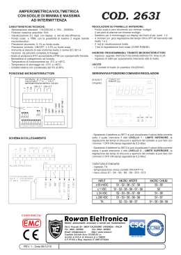
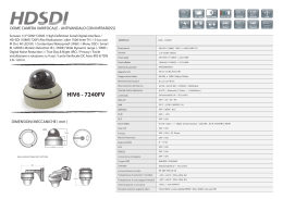
L8542600
Rev. 10/04/02
CENTRALE DI COMANDO
CONTROL UNIT
STEUEREINHEIT
CENTRALE DE COMMANDE
CENTRAL DE MANDO
CENTRALKA STEROWANIA
DA.93AM
Libro istruzioni
Operating instructions
Betriebsanleitung
Livret d’instructions
Manual de instrucciones
Książeczka z instrukcjami
UNIONE NAZIONALE COSTRUTTORI
AUTOMATISMI PER CANCELLI, PORTE,
SERRANDE ED AFFINI
Dichiarazione CE di conformità
EC declaration of confirmity
EG-Konformitatserklarung
Déclaration CE de conformité
Declaracion CE de conformidad
Deklaracja UE o zgodności
Con la presente dichiariamo che il nostro prodotto
We hereby declare that our product
Hiermit erklaren wir, dass unser Produkt
Nous déclarons par la présente que notre produit
Por la presente declaramos que nuestro producto
Niniejszym oświadczamy że nasz produkt
DA.93AM
è conforme alle seguenti disposizioni pertinenti:
complies with the following relevant provisions:
folgenden einschlagigen Bestimmungen entspricht:
correspond aux dispositions pertinentes suivantes:
satisface las disposiciones pertinentes siguientes:
zgodny jest z poniżej wyszczególnionymi rozporządzeniami:
Direttiva sulla compatibilità elettromagnetica (89/336/
CCE, 93/68/CEE)
EMC guidelines (89/336/EEC, 93/68/EEC)
EMV-Richtlinie (89/336/EWG, 93/68/EWG)
Directive EMV (89/336/CCE, 93/68/CEE) (Compatibilité
électromagnétique)
Reglamento de compatibilidad electromagnética (89/336/
MCE, 93/68/MCE)
Wytyczna odnośnie zdolności współdziałania elektromagnetycznego (89/336/EWG, 93/68/EWG)
Direttiva sulla bassa tensione (73/23/CEE, 93/68/CEE)
Low voltage guidelines (73/23/EEC, 93/68/EEC)
Tiefe Spannung Richtlinie (73/23/EWG, 93/68/EWG)
Directive bas voltage (73/23/CEE, 93/68/CEE)
Reglamento de bajo Voltaje (73/23/MCE, 93/68/MCE)
Wytyczna odnośnie niskiego napięcia (73/23/EWG, 93/
68/EWG)
Norme armonizzate applicate in particolare:
Applied harmonized standards, in particular:
Angewendete harmonisierte Normen, insbesondere:
Normes harmonisée utilisées, notamment:
Normas armonizadas utilzadas particularmente:
Normy standard najczęściej stosowane:
Norme armonizzate applicate in particolare:
Applied harmonized standards, in particular:
Angewendete harmonisierte Normen, insbesondere:
Normes harmonisée utilisées, notamment:
Normas armonizadas utilzadas particularmente:
Normy standard najczęściej stosowane:
EN 55022, EN 61000-3-2, EN 61000-3-3, EN 50082-1
EN 60204-1, EN 60335-1
Data/Firma
Data/Firma
Automatismi Benincà Srl
Via Capitello, 45
36066 Sandrigo (VI)
ITALIA
2
230
FUSE
5
SPUNTO
4
RL2
VDR5
F1
6,3A
FF2
MAX.
MIN.
MOTOR POWER
2
VDR1
SW1
F2
FUSE
2A
3
1
R24
R23
TRF1
190
170
140
120
0
COMUNE
RL1
6
C5
FF7
7
C19
C18
C17
C16
C15
C14
FF3
0
FF8
FF9
FF10
FF11
APRE1
RL3
8
VDR7
R14
R13
R12
R15
R16
R17
R18
R19
R20
R21
Z10
Z9
Z8
Z7
Z6
Z5
Z4
Z1
Z2
Z3
C10
C12
C11
C13
1
VDR2
18
0
12
24
RL5
9
CHIUDE1
10
VDR6
C6
POWER
F3
D1
APRE2
RL4
11
F
D1
D2
APERTURA
C1
12
N
INPUT
230VAC 50 Hz
U1
C4
D14
I_APRE
C2
3A
CHIUDE2
RL6
VDR8
13
COM.
FUSE
C3
I_CHIUDE
F4
14
M1
COM. Chiude Apre
FF4
R2
R1
R3
R5
(POWER)
J2
D4
I_PED.
CHIUSURA
D5
I_STOP
I_P.P.
D6
I_FTCA
D3
D7
I_FTCC
D13
D8
I_FCA1
CORTESIA
VDR4 VDR3
15
RL7
16
M2
Chiude Apre
FF13
R26 R25
C4
DA.93AM
FF12
1
D9
I_FCA2
D10
D11
SCA
17
C5
18
RL8
19
I_FCC
ELS
20
Lamp. 230VAC
U3
JP1
21
D12
RL9
22
Cortesia
230VAC
C3
U6
U5
01
ON/OFF
SPUNTO
23
R1
R22
R23
R12
R13
R14
R15
R16
R17
R18
R19
R20
R21
24
Out
24VAC
U4
--
+-
FUSE
ELS
12VAC
J1
R4
C2
U2
C1
+
+
TCA
TRAC
TL
R9
R11
R7
X1
02
R6
R10
R8
SW1
10 9 8 7 6 5 4 3 2 1 OFF
C9
C8
ON
C7
Dip switch.
Dip-switch.
Dip-Drucktasten.
Dip switch.
Dip switch.
Dip switch.
Connettore scheda logica.
Logic board connection.
Logikkarte.
Connecteur fiche logique.
Connectador ficha logica.
Złącze karty sterowania
FF5
25
SCA
+V
GND
MCU1_IO
26
+V
C5
FTCA
R24
27
FCA1
J1
28
FTCC
R2
R3
R4
R5
R6
R7
R8
R9
R10
R11
29
FCC
30
FCA2
FF1
31
STOP
RTX
32
P.P.
JP2
PED.
1
33
APRE
FF6
34
ANT.
CHIUDE
3
RTX
2 CH.
Centralina DA.93AM
La centralina a microprocessore DA.93AM può essere usata con 2 motori di potenza non superiore a 750W
complessivi.
Consigli per l’installazione.
a)
L’installazione elettrica e la logica di funzionamento devono essere in accordo con le normative vigenti.
b)
È consigliabile tenere i cavi di potenza (motore, alimentazione) distinti da quelli di comando (pulsanti, fotocellule, radio); per evitare interferenze è preferibile prevedere ed utilizzare due guaine separate (vedi EN
60204-1 15.1.3).
c)
Ricontrollare tutti i collegamenti fatti prima di dare tensione.
d)
Controllare che le impostazioni dei Dip-Switch siano quelle volute.
e)
Dando tensione il led ”POWER” si deve illuminare, in caso contrario controllare l’integrità dei fusibili e la
presenza di 230VAC 50Hz tra i morsetti 1 e 2 (INPUT 230VAC - rispettare fase/neutro).
f)
Gli ingressi N.C. non usati devono essere ponticellati con il comune ”+V”.
FUNZIONI INGRESSI/USCITE
N° Morsetti
(1,2)
(3,4,5)
(9,10)
(11,12)
(13,14)
(15,16)
(17,18)
Funzione
INPUT 230VAC
COM/APRE/
CHIUDE M1
COM/APRE/
CHIUDE M2
LAMP230
CORTESIA
OUT 24VAC
ELS
SCA
(19,20)
(21)
+V
FTCA
(22)
FTCC
(23)
(24)
(25)
(26)
(27)
(28)
(29)
(30)
(31,32)
(33,34)
J1
JP1
FCA1
FCA2
FCC
STOP
PED
P.P.
APRE
CHIUDE
ANT.
RX 2CH.
RTX
SPUNTO
(6,7,8)
Descrizione
Alimentazione centralina 230VAC 50Hz (rispettare fase/neutro)
Ai rispettivi morsetti del motore a 230VAC 50Hz (ritardato in chiusura)
(è obbligatorio collegare il filo di terra - giallo/verde)
Ai rispettivi morsetti del motore a 230VAC 50Hz (ritardato in apertura)
(è obbligatorio collegare il filo di terra - giallo/verde)
Al lampeggiante a 230VAC
Alla luce di cortesia 230VAC
Uscita alimentazione ausiliaria 24VAC (1A max.)
Uscita 12VAC per elettroserratura
Contatto ”Spia cancello aperto” 24Vdc (250mA)
Funzionamento dell’uscita ”Spia cancello aperto”.
• Se il cancello è chiuso (intervento finecorsa di chiusura - fine del tempo di
lavoro in chiusura), la spia è spenta.
• Se il motore è in fase di apertura, la spia lampeggia lentamente (1Hz circa).
• Se il motore è in fase di chiusura, la spia lampeggia velocemente (2Hz
circa).
• Se il cancello è aperto (intervento finecorsa di apertura - fine del tempo di
lavoro in apertura) o la corsa viene interrotta manualmente (PP - STOP), la
spia rimane accesa.
N.B.: La spia è comandata da un relè, le commutazioni sono quindi normalmente
udibili durante il funzionamento normale della centrale.
Comune a tutti gli ingressi di comando
Ingresso ricevitore fotocellula apertura (contatto n.c.) (fotocellula più distante
dal cancello)
Ingresso ricevitore fotocellula chiusura (contatto n.c.) (fotocellula più vicina
al cancello)
Ingresso finecorsa apre motore M1 (contatto n.c.)
Ingresso finecorsa apre motore M2 (contatto n.c.) - ritardato in apertura
Ingresso finecorsa chiude motore M1 e M2 (contatto n.c.)
Ingresso pulsante STOP (contatto n.c.)
Ingresso pulsante PEDONALE (contatto n.o.)
Ingresso pulsante PASSO/PASSO (contatto n.o.)
Ingresso pulsante APRE (contatto n.o.)
Ingresso pulsante CHIUDE (contatto n.o.)
Ingresso antenna scheda radio
Contatto 2° canale scheda radio (contatto n.o.)
Connettore scheda ricevente del telecomando
Jumper di selezione ”SPUNTO” motori in partenza:
1) Chiuso: Spunto abilitato
2) Aperto: Spunto disabilitato
La potenza dei motori può essere controllata mediante il commutatore a 5 posizioni ”MOTOR POWER”.
4
La lampada di cortesia si spegne automaticamente dopo 150 secondi dall’ultima manovra effettuata.
La funzione di ”chiusura automatica” è inibita finchè il pulsante APRE rimane premuto (contatto chiuso).
Funzione Dip-Switch
N.B.:
Ogni cambio di funzione deve essere eseguito in assenza di tensione.
DSW1
Sceglie il tipo di funzionamento del ”Pulsante P.P.” e del telecomando.
Off: Funzionamento: ”APRE” - ”STOP” - ”CHIUDE” - ”STOP”
On: Funzionamento: ”APRE” - ”CHIUDE”
DSW2
Selezione ritardo motore 2 in apertura.
Off: 1 secondo
On: 3 secondi
DSW3
Funzione ”Prelampeggio”: il lampeggiante viene attivato 4 secondi prima dell’inizio di ogni manovra
Off: Prelampeggio disabilitato
On: Prelampeggio abilitato
DSW4
Abilita o disabilita l’elettroserratura
Off: Elettroserratura disabilitata
On: Elettroserratura abilitata
DSW5
Abilita o disabilita la funzione ”colpo d’ariete” per lo sblocco dell’elettroserratura. La funzione è attiva
solo se il Dip-Switch ”DSW4” è in posizione On.
Off: Colpo d’ariete disabilitato
On: Colpo d’ariete abilitato
DSW6
Abilita o disabilita la partenza contemporanea dei motori (ignora i tempi impostati dal Dip-Switch ”DSW2”
e dal trimmer TRAC).
Off: Partenza contemporanea disabilitata
On: Partenza contemporanea abilitata
DSW7
Funzione ”Condominiale”: gli ingressi ”P.P.” e ”PED.” comandano solo l’apertura dell’automatismo.
Off: Funzione ”Condominiale” disabilitata
On: Funzione ”Condominiale” abilitata
DSW8
Abilita o disabilita l’intervento dell’ingresso ”PED.” durante la chiusura di entrambi i motori.
Off: Disabilitato.
On: Abilitato. In questo caso, l’ingresso ”PED.” ha la stessa funzione dell’ingresso ”P.P.” secondo le
impostazioni del Dip-Switch ”DSW1”.
DSW9
Modo di funzionamento per l’uscita ELS (se abilitata dal Dip 4).
Off: Uscita ELS attiva solo se è terminata la fase di chiusura e all’accensione della centrale.
On: Uscita ELS attiva ad ogni manovra di apertura.
DSW10 Abilita o disabilita la richiusura automatica.
Off: Richiusura automatica abilitata
On: Richiusura automatica disabilitata
Per ragioni di sicurezza, questa funzione è sempre disabilitata a seguito di un comando di ”STOP” e
all’accensione della centrale.
Funzione dei Trimmer
TCA
Permette di regolare il tempo di richiusura automatica quando è abilitata posizionando il Dip-Switch
”DSW10”= Off.
La regolazione varia da un minimo di 10 sec. ad un massimo di 4 minuti.
Il tempo minimo si ottiene ruotando il trimmer tutto in senso antiorario.
TL
Permette di regolare il tempo di lavoro dell’automatismo oltre il quale interverrà la protezione software.
La regolazione varia da un minimo di 5 sec. ad un massimo di 100 sec.
Il tempo minimo si ottiene ruotando il trimmer tutto in senso antiorario.
TRAC
Permette di regolare il ritardo del motore 1 in fase di chiusura.
La regolazione varia in funzione della posizione del Dip-Switch ”DSW2”:
Off: da un minimo di 1 sec. ad un massimo di 12 sec.
On: da un minimo di 2 sec. ad un massimo di 24 sec.
Il tempo minimo si ottiene ruotando il trimmer tutto in senso antiorario.
5
DA.93AM Control unit with microcontroller
The control unit ”DA.93AM” can be used with motors having a total power not exceeding 750W.
Installation instructions.
a) The electric installation and the operating logic must comply with regulations in force.
b) It is advisable to keep the power cables (motor, power supply) detached from the control cables (push-buttons, photocells, radio). In order to avert any possible interference it is recommended to provide for and use
two separate sheaths (see EN 60204-1 15.1.3).
c) Before powering the unit, check again all connections which have been carried out.
d) Check that the presettings of the Dip-Switches are correct.
e) When the unit is powered, the LED “POWER” must be lit; in the negative, check that fuses are in
good condition and that 230Vac 50Hz power supply is present between terminals 1 and 2 (INPUT 230VAC
- keep to line/ground connection).
f)
The N.C. inputs not used must be connected to the common “+V”.
Input/Output functions
Terminal No.
Function
Description
(1,2)
INPUT 230VAC
Control unit 230Vac 50 Hz power supply (respect phase/neutral wire
position).
(3,4,5)
COM/APRE/
CHIUDE M1
Connection to the corresponding 230Vac 50 Hz motor terminals (delayed
in closing) (the earth wire (green/yellow) must be connected).
(6,7,8)
COM/APRE/
CHIUDE M2
Connection to the corresponding 230Vac 50 Hz motor terminals (delayed
in opening) (the earth wire (green/yellow) must be connected).
(9,10)
LAMP230
Connection to the 230Vac blinker.
(11,12)
CORTESIA
Connection to the 230Vac courtesy lamp.
(13,14)
OUT 24VAC
24Vac auxiliary power supply output (1Amax.).
(15,16)
ELS
12Vac output for electric lock.
(17,18)
SCA
24Vdc ”Gate open warning light” contact (250mA).
Function for the ”Gate open warning light” contact.
•If the gate is closed, the warning light is turned off.
•If the gate is opening, the warning light flashes slow (about 1Hz).
•If the gate is closing, the warning light flashes fast (about 2Hz).
•If the gate is open, or the race is interrupted manually (PP - STOP), the
warning light remains turned on.
N.B.: The led is driven by a relay, thus the commutation can be normally
heard during the normal function of the control board.
(19,20)
+V
Common connection to all the control inputs.
(21)
FTCA
Opening photocell receiver input (n.c. contact) (photocell far from the
gate).
(22)
FTCC
Closing photocell receiver input (n.c. contact) (photocell near the gate).
(23)
FCA1
Limit switch input - M1 motor opening (n.c. contact).
(24)
FCA2
Limit switch input - M2 motor opening (n.c. contact) - opening delay.
(25)
FCC
Limit switch input - M1 and M2 motor closing (n.c. contact).
(26)
STOP
STOP button input (n.c. contact).
(27)
PED
PEDESTRIAN button input (n.o. contact).
(28)
P.P.
STEP-by-STEP button input (n.o. contact).
(29)
APRE
OPEN button input (n.o. contact).
(30)
CHIUDE
CLOSE button input (n.o. contact).
(31,32)
ANT.
Input of radio board antenna
(33,34)
RX 2CH.
Radio board 2nd channel contact (n.o. contact).
J1
RTX
Connector for receiver board of the remote control
JP1
SPUNTO
Selection jumper, “PICKUP” of starting motors
1) Closed : enabled pickup
2) Open : inhibited pickup
The power of motors can be controlled through the 5-step commutator “MOTOR POWER”.
6
The courtesy lamp switches off automatically after 150 seconds from the last operation being carried out.
The “automatic closure” function is inhibited until the OPEN push-button is pressed (closed contact).
Dip-switch functions
N.B.:
Every change of functions have to be done without electricity.
DSW1= This selects the type of functioning of the P.P. button and Remote control.
Off= ”OPEN” - ”STOP” - ”CLOSE” - ”STOP” functioning
On= ”OPEN” - ”CLOSE” functioning.
DSW2= Selection of delayed motor 2 in the opening phase.
Off= 1 second
On= 3 seconds
DSW3= With this Dip-Switch the forewarning flashing is enabled or inhibited 4 seconds before each operation.
Off= Foreflashing is inhibited
On= Foreflashing is enabled
DSW4= With this Dip-Switch the electric lock is enabled or inhibited.
Off= Electric lock isnhibited
On= Electric lock is enabled
DSW5= It inhibits or enables the “stroke” function for the release of the electric lock. The function can be activated
only if the Dip-Switch “DSW4” is in position ON.
Off= Stroke inhibited
On= Stroke enabled
DWS6= The simultaneous start of the motors is inhibited or enabled (the times preset by Dip-Switch “DSW2”
and by trimmer TRAC are bypassed).
Off= Simultaneous starting inhibited
On= Simultaneous starting enabled
DSW7= Multiple-user function for blocks of flats: the “P.P.” and “PED” inputs control only the opening of the
system.
Off= ultiple-user function inhibited
On= Multiple-user function enabled
DSW8= It enables or inhibits the intervention of input “PED” during the closing phase of both motors.
Off= Inhibited
On= Enabled. In this case the “PED” input has the same function of the “P.P.” input, according to the
presettings of the Dip-Switch “DSW1”.
DSW9= Operating mode for ELS output (if enabled by Dip 4).
Off= ELS output is activated only when the closure is completed and the control unit is on.
On= ELS output is activated at every opening operation.
DSW10= It enables or inhibits the automatic closure.
Off= automatic closure is enabled
On= automatic closure is inhibited
For safety reasons this function is always inhibited after a “STOP” control signal is given and the control
unit hs been switched on.
Trimmer functions
TCA= It allows the regulation of the automatic closure when the Dip-switch “DSW10”= Off.
The adjustment varies from 10 sec. minimum to 4 minutes maximum.
The minimum time is obtained by turning the trimmer completely anticlockwise.
TL=
It allows the adjustment of the operating time of the automatic system. When the time has elapsed the
software protection will be activated.
The adjustment varies from 5 sec. minimum to 100 sec. maximum.
The minimum time is obtained by turning the trimmer completely anticlockwise.
TRAC= It allows the adjustment of the motor 1 delay in the closing phase.
The adjustment varies according to the position of the “DSW2” Dip-Switch.
Off= from 1 sec. minimum to 12 sec. maximum
On= from 2 sec. minimum to 24 sec. maximum
The minimum time is obtained by turning the trimmer completely anticlockwise.
7
STEUERUNG ”DA.93AM”
Die Mikrocontroller-Steuerung ”DA.93AM” kann mit 2 Motoren mit einer Gesamtleistung von nicht über 750W
verwendet werden.
Empfehlungen für den Einbau
a) Die Elektromontage und die Funktionslogik müssen den gesetzlichen Vorschriften entsprechen.
b) Es wird empfohlen, die Leistungskabel (Motor, Speisung) von den Befehlskabeln (Tasten, Lichtschranke, Funk)
zu trennen. Um Störungen zu vermeiden, sollten zwei getrennte Mäntel verwendet werden (siehe EN 60204-1
15.1.3).
c) Bevor die Anlage ans Stromnetz angeschlossen wird, alle Verbindungen kontrollieren.
d) Einstellungen der Dip-Switch überprüfen.
e) Bei Stromgabe muß das Led “POWER” aufleuchten. Andernfalls Zustand der Sicherungen kontrollieren und
ebenfalls die Spannung zwischen den Klemmen 1 und 2, die 230Vac 50 Hz betragen soll (INPUT 230VAC
- Phase/neutral beachten)
f) Die N.C. Eingaben, die nicht verwendet werden, mit dem Mittelleiter “+V” überbrücken.
Funktion Eingaben/Ausgaben
Anzahl
Klemmen
(1,2)
(3,4,5)
(6,7,8)
Funktion
Beschreibung
INPUT 230VAC
COM/APRE/
CHIUDE M1
Zufuhr Steuerung 230Vac 50Hz (Phase/Neutral beachten).
An die entsprechenden Motorklemmen 230Vac 50Hz (verzeugert bei Schließung) (Es ist Vorschrift, den Erdleiter (gelb/grün) mit dem Motorgehäuse zu
verbinden)
An die entsprechenden Motorklemmen 230Vac 50Hz (verzeugert bei Öffnung) (Es
ist Vorschrift, den Erdleiter (gelb/grün) mit dem Motorgehäuse zu verbinden)
An 230Vac Blinkleuchte.
An 230Vac Innenleuchte.
Ausgabe Hilfszufuhr 24Vac (max. 1A).
An Elektroschloß Ausgabe 12Vac.
Kontakt ”Torblinker Auf” 24Vdc (250 mA).
Funktion des Ausgangs ”Lampe Tor geöffnet”.
• Wenn das Tor geschlossen ist (Eingriff Laufende von Schließung), die Lampe
ist aus.
• Wenn der Motor geöffnet wird, blinkt die Lampe langsam (ungefähr 1Hz).
• Wenn der Motor geschlossen wird, blinkt die Lampe schnell (ungefähr 2Hz).
• Wenn das Tor geöffnet ist (Eingriff Laufende während der Öffnung - Ende der
Betriebszeit während der Öffnung) oder der Lauf wird von Hand unterbrochen
(PP - STOP), die Lampe bleibt geöffnet.
N.B.: Die Lampe wird von einem Relais angetrieben. Die Vertauschungen
können daher normalerweise während des normalen Antriebs der Zentrale
gehört werden.
Gemeinsam bei allen Steuereingaben.
Eingabe Lichtschrankenempfänger öffnung (Ruhekontakt) vom Tor entfernteste
Lichtschranke).
Eingabe Lichtschrankenempfänger Schließung (Ruhekontakt) am Tor nähere
Lichtschranke)
Eingabe Endschalter Motor M1 Öffnet (Ruhekontakt)
Eingabe Endschalter Motor M2 Öffnet (Ruhekontakt) - verzeugert bei öffnung
Eingabe Endschalter Motor M1 und M2 schließen (Ruhekontakt)
Eingabe STOP-Drucktaste (Ruhekontakt)
Eingabe Drucktaste Flügel FUSSGÄNGER (Arbeitskontakt)
Eingabe SCHRITT/SCHRITT-Drucktaste (Arbeitskontakt)
Eingabe ÖFFNET-Drucktaste (Arbeitskontakt)
Eingabe SCHLIESST-Drucktaste (Arbeitskontakt)
Eingabe Antenne Empfängersteckkarte
Kontakt 2. Kanal Empfängersteckkarte (Arbeitskontakt)
Verbinder Empfängerkarte der Fernbedienung
Jumper zur Wahl “Anlasstoß” Motoren beim Start
1) Geschlossen: Anlasstoß freigegeben
2) Offen: Anlasstoß nicht freigegeben
(9,10)
(11,12)
(13,14)
(15,16)
(17,18)
COM/APRE/
CHIUDE M2
LAMP230
CORTESIA
OUT 24VAC
ELS
SCA
(19,20)
(21)
+V
FTCA
(22)
FTCC
(23)
(24)
(25)
(26)
(27)
(28)
(29)
(30)
(31,32)
(33,34)
J1
JP1
FCA1
FCA2
FCC
STOP
PED
P.P.
APRE
CHIUDE
ANT.
RX 2CH.
RTX
SPUNTO
Die Motorleistung kann durch einen 5-stelligen ”MOTOR POWER” Umschalter gesteuert werden. Die Höflichkeitsleuchte schaltet automatisch 150 Sekunden nach dem letzten Vorgang aus.
Die Funktion ”automatisch schließen” bleibt gesperrt solange die Taste ÖFFNEN gedrückt bleibt (Ruhekontakt).
8
Funktion der Dip-Drucktasten
Anmerkung: Alle Funktionsänderung muß in Mangel von Spannung verricht werden.
DSW1 Wählt die Funktionsart der “Taste P.P.” und der Fernbedienung
Off: Funktionsart “ÖFFNEN” - “STOP” - “SCHLIESSEN” - “STOP”
On: Funktionsart “ÖFFNEN” - “SCHLIESSEN”
DSW2 Wählt verzögertes Öffnen Motor 2
Off: 1 Sekunde
On: 3 Sekunden
DSW3 Funktion Vorblinken: Die Blinkleuchte wird 4 Sekunden vor dem Start eines Vorgangs aktiviert.
Off: Vorblinken nicht freigegeben
On: Vorblinken freigegeben
DSW4 Aktiviert oder entaktiviert das elektrische Schloß
Off: Elektrisches Schloß nicht freigegeben
On: Elektrisches Schloß freigegeben
DSW5 Aktiviert oder entaktiviert die Funktion ”Druckstoß” zum Entarretieren des elektrischen Schlosses.
Off: Druckstoß nicht freigegeben
On: Druckstoß freigegeben
DSW6 Aktiviert oder Entaktiviert das gleichzeitige Starten der Motoren (ohne Rücksichtnahme auf Dip-Switch
”DSW2” und Trimmer TRAC)
Off: Gleichzeitige Starten nicht freigegeben
On: Gleichzeitige Starten freigegeben
DSW7 Mehrfamilienfunktion: die Eingänge ”P.P.” und ”PED” steuern nur das Öffnen der Automatik.
Off: Mehrfamilienfunktion nicht freigegeben
On: Mehrfamilienfunktion freigegeben
DSW8 Aktiviert oder entaktiviert den Eingang ”PED” beim Schließen beider Motoren.
Off: nicht freigegeben
On: freigegeben; in diesem Fall hat der Eingang ”PED” dieselbe Funktion wie Eingang ”P.P.” entsprechend
der Einstellung des Dip-Switch ”DSW1”.
DSW9 Betriebsart für den ELS Ausgang (wenn durch Dip 4 freigegeben).
Off: Freigegeben
On: Nicht freigegeben
DSW10 Aktiviert oder entaktiviert das automatische Schließen
Off: automatisches Schließen nicht freigegeben
On: automatisches Schließen freigegeben
Aus Sicherheitsgründen ist diese Funktion stets entaktiviert nachdem ein ”STOP” Befehl gegeben oder
die Zentrale eingeschaltet worden ist.
Funktion der Trimmer
TCA
Ermöglicht das Einstellen der automatischen Schließzeit, wenn sie durch den Dip-Switch,”DSW10”= Off
aktiviert ist.
Die Schließzeit kann zwischen mindestens 10 Sekunden und maximal 4 Minuten eingestellt werden.
Durch Drehen des Trimmers in den Uhrzeigersinn wird die minimale Zeiteinstellung erzielt.
TL
Ermöglicht das Einstellen der Arbeitszeit der Automatikanlage. Bei ihrem überschreiten greift der
Softwareschutz ein.
Die Einstellung variiert von min. 5 Sek. bis max. 100 Sek.
Die Minimalzeiteinstellung wird durch Drehen des Trimmer in den Uhrzeigersinn erreicht.
TRAC
Ermöglicht die Zeitverzögerung des Motors 1 beim Schließen.
Die Einstellung variiert je nach Einstellung des Dip-Switch ”DSW2”
Off: mindestens 1 sec. bis max. 12 sec.
On: mindestens 2 sec. bis max. 24 sec.
Die Minimalzeiteinstellung wird durch Drehen des Trimmer in den Uhrzeigersinn erreicht.
9
Centrale ”DA.93AM”
La centrale à microprocesseur DA.93AM peut être utilisée avec deux moteurs d’une puissance totale non supérieure à 750W.
Conseils pour l’installation
a) L’installation électrique et la logique de fonctionnement doivent être conformes aux normes en vigueur.
b) Il est conseillé de maintenir les câbles de puissance (moteur, alimentation) séparés de ceux de commande
(touches, cellules photoélectriques, radio); afin d’éviter des interférences, il est préférable de prévoir et d’utiliser
deux gaines séparées (voir EN 60204-1 15.1.3).
c) Recontrôler toutes les connexions effectuées avant d’appliquer la tension.
d) S’assurer que les réglages des interrupteurs DIP soient corrects.
e) En appliquant la tension, le DEL ”POWER” doit s’allumer; si cela n’etait pas le cas, contrôler le bon fonctionnement des fusibles et la présence des 230Vca 50 Hz entre les bornes 1 et 2 (INPUT 230VAC - respecter
phase/neutre).
f) Réaliser un pontet entre les entrées N.C. pas utilisées et le commun ”+V”.
Fonction Entrées/Sorties
N° Bornes
(1,2)
(3,4,5)
(9,10)
(11,12)
(13,14)
(15,16)
(17,18)
Función
INPUT 230Vac
COM/APRE/
CHIUDE M1
COM/APRE/
CHIUDE M2
LAMP230
CORTESIA
OUT 24VAC
ELS
SCA
(19,20)
(21)
+V
FTCA
(22)
FTCC
(23)
(24)
(25)
(26)
(27)
(28)
(29)
(30)
(31,32)
(33,34)
J1
JP1
FCA1
FCA2
FCC
STOP
PED
P.P.
APRE
CHIUDE
ANT.
RX 2CH.
RTX
SPUNTO
(6,7,8)
10
Descripción
Alimentation centrale 230Vca 50 Hz (respecter phase/neutre)
Aux bornes correspondantes du moteur 230Vca 50 Hz(retardé en fermeture) (il
est obligatoire de connecter le fil de terre (jaune/vert) à la carcasse du moteur)
Aux bornes correspondantes du moteur 230Vca 50 H(retardé en ouverture) (il est
obligatoire de connecter le fil de terre (jaune/vert) à la carcasse du moteur)
Au feu clignotant à 230Vca
Vers la lumière de courtoisie 230Vca
Sortie alimentation auxiliaire 24Vca (1A max)
Sortie 12 Vca pour electroserrure
Contact ”Témoin portail ouvert” 24Vdc (250 mA)
Fonctionnement de la sortie ”Témoin portail ouvert”.
• Si le portail est fermé (intervention fin de course de fermeture - fin du temps
de travail en fermeture), le témoin est éteint.
• Si le moteur est en train de ouvrir, le témoin étincele lentement (1Hz à peut
prêt).
• Si le moteur est en train de fermer, le témoin étincele velocement (2Hz à peut
prêt).
• Si le moteur est ouvert (intervention fin de course de ouverture - fin de temps
de travail en ouverture) ou la course est fermée manuellement (PP - STOP),
le témoin reste en fonction.
N.B.: Le témoin est commandé par un relé donc les commutations peuvent être
normallement écouter pendant le fonctionnement normal de la centrale.
Commun à toutes les entrées de commande
Entrée recepteur cellule photoélectrique ouverture (contact n.f. - photocellule
la plus éloignée du portail)
Entrée recepteur cellule photoélectrique fermeture (contact n.f. - photocellule
la plus proche du portail)
Entrée fin de course Ouvre M1 (contact n.f.)
Entrée fin de course Ouvre M2 (contact n.f.) retardée en ouverture
Entrée fin de course Ferme moteur M1 et M2 (contact n.f.)
Entrée touche STOP (contact n.f.)
Entrée touche PASSAGE PIETON (contact n.o.)
Entrée touche PAS à PAS (contact n.o.)
Entrée touche OUVRE (contact n.o.)
Entrée touche FERME (contact n.o.)
Entrée antenne carte radio
Contact 2° canal carte radio (contact n.o.)
Connecteur carte récepteur de la télécommande
Jumper de sélection ”EXCITATION” moteurs au démarrage
1) fermé: Excitation validée
2) Ouvert: Excitation invalidée
La puissance des moteurs peut être contrôlée par le commutateur à 5 positions ”MOTOR POWER”.
La lampe de courtoisie s’éteint automatiquement 150 secondes après la dernière manoeuvre effectuée.
La fonction de ”fermeture automatique” demeure inhibée tant qu’on exerce une pression sur la touche OUVRE
(Contact fermé).
Fonction interrupteurs DIP
N.B.: Tous les échanges de fonction doivent être effectués dans l’absence de tension.
DSW1 Choisit le type de fonctionnement de la ”Touche P.P.” et de la télécommande
Off: Fonctionnement ”OUVRE” - ”STOP” - ”FERME” - ”STOP”
On: Fonctionnement: ”OUVRE” - ”FERME”
DSW2 Sélection retard moteur 2 en ouverture
Off: 1 seconde
On: 3 secondes
DSW3 Fonction ”Préclignotement”: le clignotement est activé 4 secondes avant le début de chaque manoeuvre.
Off: Préclignotement invalidé
On: Préclignotement validé
DSW4 Valide ou invalide la gâche électrique
Off: Gâche électrique invalidée
On: Gâche électrique validée
DSW5 Valide ou invalide la fonction ”coup de bélier” pour le déverrouillage de la gâche électrique.
La fonction est active seulement si le Dip-Switch DSW4 est sur ON.
Off: Coup de bélier invalidé
On: Coup de bélier validé
DWS6 Valide ou invalide le démarrage simultané des moteurs (Ignore les temps programmés par le Dip-Switch
”DSW2” et par le trimmer TRAC)
Off: Démarrage simultané invalidé
On: Démarrage simultané validé
DSW7 Fonction ”Copropriété”, les entrées ”P.P.” et ”PED” commandent seulement l’ouverture de l’automatisme.
Off: Fonction ”Copropriété” invalidée.
On: Fonction ”Copropriété” validée.
DSW8 Valide ou invalide l’intervention de l’entrée "PED" durant la fermeture des deux moteurs.
Off: invalidé
On: validé. Dans ce cas, l'entrée ”PLD” a la même fonction que l'entrée ”P.P.”, selon les programmations
du Dip-Switch "DSW1”
DSW9 Mode de fonctionnement pour la sortie ELS (si validée par le Dip-Switch 4).
Off: Sortie ELS active seulement si la phase de fermeture est terminée et à l’allumage de la centrale.
On: Sortie ELS active dans toutes les manoeuvres d’ouverture.
DSW10 Valide ou invalide la refermeture automatique.
Off: Refermeture automatique validée
On: Refermeture automatique invalidée
Pour des raisons de sécurité, cette fonction est toujours invalidée et elle est suivie d'une commande de
"STOP" et de l’allumage de la centrale.
Fonction des potentiomètre
TCA
Permet de régler le temps de refermeture automatique lorsque cette fonction est validée en plaçant le
Dip-Switch ”DSW10” = Off.
Le réglage varie d’un minimum de 10 sec à un maximum de 4 minutes.
Le temps minimum s’obtient en tournant complètement le trimmer dans le sens contraire des aiguilles
d'une montre.
TL
Il permet de régler le temps de travail de l'automatisme au-delà duquel la protection du logiciel intervient.
Le réglage varie d'un minimum de 5 secondes à un maximum de 100 sec.
Le temps minimum s'obtient en tournant complètement le trimmer dans le sens contraire des aiguilles
d'une montre.
TRAC Il permet de régler le retard du moteur 1 durant la fermeture.
Le réglage varie en fonction de la position du Dip-Switch "DSW2"
Off: d'un minimum de 1 sec. à un maximum de 12 sec.
On: d'un minimum de 2 sec. à un maximum de 24 sec.
Le temps minimum en tournant complètement le trimmer dans le sens contraire des aiguilles d'une
montre.
11
Central a microprocesador DA.93AM
La central a microprocesador “DA93AM” puede ser usada con 2 motores de pontencia total no superior a
750W.
Consejos para la instalacion
a) La instalación eléctrica y la lógica de funcionamiento deben estar de acuerdo con la normativa vigente.
b) Es aconsejable tener los cables de potencia (motor, alimentación) separados de los de mando (pulsadores,
fotocélulas, radio) para evitar interferencias es preferible preveer de utilizar dos tubos separados (véase
EN60204-1 15.1.3).
c) Repasar todas las conexiones antes de dar tensión.
d) Controlar que la imposición de los Dip-Switch es la deseada.
e) Dando tensión el led ”Power” se debe iluminar, en caso contrario controlar la integridad de los fusibles y la
presencia de 230Vac 50 Hz entre los bornes 1 y 2 (Entrada 230Vac - respetar fase/neutro).
f) Las entradas N.C. no utilizadas deben ser puenteadas con el común ”+V”.
Funcion Entradas / Salidas
N° Bornes
Función
Descripción
(1,2)
(3,4,5)
(9,10)
(11,12)
(13,14)
(15,16)
(17,18)
INPUT 230VAC
COM/APRE/
CHIUDE M1
COM/APRE/
CHIUDE M2
LAMP230
CORTESIA
OUT 24VAC
ELS
SCA
(19,20)
(21)
+V
FTCA
(22)
FTCC
(23)
(24)
FCA1
FCA2
(25)
(26)
(27)
(28)
(29)
(30)
(31,32)
(33,34)
J1
JP1
FCC
STOP
PED
P.P.
APRE
CHIUDE
ANT.
RX 2CH.
RTX
SPUNTO
Alimentación central 230Vac 50 Hz (respetar fase/neutro)
A los respectivos bornes motor 230Vac 50 Hz (retardado en cierre) (es obligatorio conectar el cable de tierra - amarillo/verde)
A los respectivos bornes motor 230Vac 50 Hz (retardado en apertura)(es
obligatorio conectar el cable de tierra - amarillo/verde)
Al relampagueador a 230Vac
(A la luz de cortesía 230Vac
Salida de alimentación auxiliar a 24Vac (1A máximo )
Salida 12 Vac para electrocerradura
Contacto “Piloto cancela abierta” 24Vdc (250 mA)
Función de la salida ”Piloto de cancela abierta”.
• Si la cancela está cerrada (intervención de fin de carrera de cierro - fin de
tiempo de trabajo en cierro), el piloto está apagado.
• Si el motor está abriendose, el piloto relampagüea despacio (unos 1Hz).
• Si el motor está cerrandose, el piloto relampagüea velocemente (2Hz).
• Si la cancela está abierta (intervención fin de carrera - fin de tiempo de
trabajo en abiertura), o la carrera es interrumpida manualmente (PP - STOP),
el piloto se queda encendido.
N.B.: El piloto es comandado por un relé: las conmutaciones puedes ser
normalmente oídas durante la función normal de la central.
Común para todos las entradas de mando
Entrada receptor fotocélula apertura (contacto n.c.) (Fotocélula más lejana
de la cancela)
Entrada receptor fotocélula cierre (contacto n.c.) (Fotocélula más próxima
a la cancela)
Entrada final de carrera abrir motor M1 (contacto n.c.)
Entrada final de carrera abrir motor M2 ( contacto n.c.) - retardado en
apertura
Entrada final de carrera cerrar motores motores M1 y M2 (contacto n.c.)
Entrada pulsador STOP ( contacto n.o.)
Entrada pulsador PEATONAL (contacto n.o.)
Entrada pulsador PASO A PASO (contacto n.o.)
Entrada pulsador ABRIR (contacto n.o.)
Entrada pulsador CERRAR ( contacto n.o.)
Entrada antena tarjeta radio
Contacto 2° canal radio (contacto n.o.)
Conector tarjeta receptora del mando a distancia
Puente de selección “DESPUNTE” motor en arranque
1) Cerrado: despunte habilitado
2) Abierto: despunte deshabilitado
(6,7,8)
12
La potencia de los motores se puede controlar mediante el conmutador de 6 posiciones ”MOTOR POWER”.
La lámpara de cortesía se apaga automáticamente al cabo de 150 segundos contados desde la última maniobra
efectuada.
La función de ”Cierre automático” queda inhibida mientras tanto quede pulsado el botón ABRE (contacto cerrado).
Funcion Dip-Switch
NOTA: Para cambio de función debe ser realizado en ausencia de tensión.
DSW1
Elige el tipo de tarea del ”Botón P.P.” y del mando a distancia.
OFF= Funcionamiento: ABRE - STOP- CIERRA - STOP
ON= Funcionamiento: ABRE - CIERRA
DSW2
Selecciona el atraso del motor 2 en apertura.
OFF= 1 segundo
ON= 3 segundos
DSW3
Función ”Preintermitente”: el intermitente es activado 4 segundos antes del comienzo de cada maniobra.
OFF= Preintermitente inactivado
ON= Preintermitente activado
DSW4
Habilita o inhabilita la cerradura eléctrica.
OFF= Cerradura eléctrica inhabilitada
ON= Cerradura eléctrica habilitada
DSW5
Habilita o inhabilita la función ”Golpe de ariete” para el desbloqueo de la cerradura eléctrica.
La función está activa sólo si el Dip-Switch ”DSW4” está en la posición On.
OFF= Golpe de ariete inhabilitado
ON= Golpe de ariete habilitado
DSW6
Habilita o inhabilita el arranque contemporáneo de los motores (ignora los tiempos establecidos por
los Dip-Switch ”DSW2” y por el Trimmer TRAC).
OFF= Arranque contemporáneo inhabilitado
ON= Arranque contemporáneo habilitado
DSW7
Función ”Bloque de pisos”: las entradas ”P.P.” y ”PED” mandan sólo la apertura del automatismo.
OFF= Función ”Bloque de pisos” inhabilitada
ON= Función ”Bloque de pisos” habilitada
DSW8
Habilita o inhabilita la entrada ”PED” durante el cierre de ambos motores.
OFF= Inhabilitada
ON= Habilitada. En este caso la entrada ”PED” tiene la misma función que la entrada ”P.P.” según la
posición del microinterruptor ”DSW1”
DSW9
Modo de funcionamiento para la salida ELS (si habilitada por el ”DSW4”).
OFF= Salida ELS activa sólo si ha terminado la fase de cierre y al encendido de la central.
ON= Salida ELS activa a cada nueva maniobra do apertura.
DSW10 Habilita o inhabilita el cierre automático.
OFF= Cierre automático habilitado
ON= Cierre automático inhabilitado
Por razones de seguridad esta función está siempre inhabilitada después de un mando de ”STOP” y
cuando se enciende la centralita.
Funcion de Trimmer
TCA
Permite regular el tiempo de cierre automático cuando está habilitado colocando en OFF el microinterruptor ”DSW10”.
El ajuste va desde un mínimo de 10 segundos hasta un máximo de 4 minutos.
El tiempo mínimo se obtiene girando el trimmer todo en sentido antihorario.
TL
Permite regular el tiempo de trabajo del automatismo más allá del cual interviene la protección software.
El ajuste va desde un mínimo de 5 segundos hasta un máximo de 100 segundos.
El tiempo mínimo se obtiene girando el trimmer todo en sentido antihorario.
TRAC
Permite regular el atraso del motor 1 en la fase de cierre.
El ajuste cambia según la posición del microinterruptor ”DSW2”:
OFF= desde un mínimo de 1 seg. hasta un máximo de 12 seg.
ON= desde un mínimo de 2 seg. hasta un máximo de 24 seg.
El tiempo mínimo se obtiene girando el trimmer todo en sentido antihorario.
13
Centralka DA.93AM
Centralka z mikroprocesorem DA.93AM może być używana do dwu silników o łącznej mocy nie większej jak 750W.
UWAGI OGÓLNE
a)
b)
c)
d)
e)
f)
Instalacja elektryczna i sposób funkcjonowania muszą być zgodne z obowiązującymi normami.
Sugeruje się oddzielenie przewodów mocy (silnik, zasilanie) od przewodów sterowania (przyciski, fotokomórki,
radio); w celu uniknięcia zakłóceń należy zastosować dwie różne osłony przewodów (zobacz normy EN 60204-1
15.1.3).
Przed włączeniem napięcia należy sprawdzić wszystkie połączenia.
Sprawdzić czy wszystkie ustawienie dip-switchów są w żądanej pozycji.
Po włączeniu napięcia led ”POWER” powinien się zaświecić, w przeciwnym przypadku należy sprawdzić bezpieczniki
topikowe i występowanie zasilania 230Vac, 50Hz między zaciskami 1 i 2 (INPUT 230VAC – przestrzegać faza/
zerowy).
Nieużywane wejścia N.C. muszą być zmostkowane ze wspólnym ”+V”.
Nr Zacisku
(1,2)
(3,4,5)
(6,7,8)
(9,10)
(11,12)
(13,14)
(15,16)
(17,18)
(19,20)
(21)
(22)
(23)
(24)
(25)
(26)
(27)
(28)
(29)
(30)
(31,32)
(33,34)
J1
JP1
14
Funkcja
INPUT 230VAC
WSPóL./
OTWIERA/
ZAMYKA M1
WSPóL./
OTWIERA/
ZAMYKA M2
LAMP230
CORTESIA
OUT 24VAC
ELS (Zam. el.)
SCA (Lamp.
kontr. brama
otw.)
+V
FTCA (Fotokom.
otw.)
FTCC (Fotokom
zam.)
FCA1 (Wył. krań.
otw.1)
FCA2 (Wył. krań.
otw.2)
FCC (Wył. krań.
zam.)
STOP
PED (Pieszy)
P.P
OTWIERA
ZAMYKA
ANT.
RX 2CH.
RTX
SPUNTO
Funkcje Wejść – Wyjść
Opis
Zasilanie centralki 230VAC 50Hz (przestrzegać faza/zerowy)
Do odpowiednich zacisków silnika 230VAC 50Hz (z fazą opóźnienia przy
otwieraniu) (należy obowiązkowo podłączyć przewód uziemienia – żółtozielony)
Do odpowiednich zacisków silnika 230VAC 50Hz (z fazą opóźnienia przy
otwieraniu) (należy obowiązkowo podłączyć przewód uziemienia – żółtozielony)
Do ostrzegawczej lampy błyskającej na 230 VAC
Do oświetlenia na 230 VAC
Wyjście zasilania dodatkowego 24VAC (1A max.)
Wyjście 12 VAC zamka elektrycznego
“Brama otwarta” 24Vdc (250mA)
Działanie wyjścia lampki kontrolnej “Brama otwarta”
• Jeżeli brama jest zamknięta (na skutek operacji wyłącznika krańcowego
zamykania – koniec cyklu pracy zamykania), lampka kontrolna nie świeci się.
• Jeżeli silnik jest w fazie otwierania, częstotliwość błyskania lampki kontrolnej
jest mała (około 1 Hz).
• Jeżeli silnik jest w fazie zamykania, częstotliwość błyskania lampki kontrolnej
jest duża (około 2 Hz).
• Jeżeli brama jest otwarta (na skutek operacji wyłącznika krańcowego otwierania
– koniec cyklu pracy otwierania), lub jeżeli posuw bramy zostaje zatrzymany na
skutek manewru ręcznego (PP - STOP), lampka kontrolna świeci się.
N.B.: Lampka kontrolna sterowana jest przez przekaźnik, co oznacza, że przy
prawidłowym działaniu centralki słyszalne są operacje komutacji.
Wspólny wszystkich wejść sterowania
Wejście odbiornika fotokomórki otwierania ( zestyk n.c. normalnie zwarty) (
fotokomórka w pewnej odległości od bramy).
Wejście odbiornika fotokomórki zamykania ( zestyk n.c. normalnie zwarty) (
fotokomórka bliżej bramy).
Wejście wyłącznika krańcowego otwierania silnika M1 ( zestyk n.c. normalnie
zwarty)
Wejście wyłącznika krańcowego otwierania silnika M2 ( zestyk n.c. normalnie
zwarty) – z fazą opóźnienia przy otwieraniu
Wejście wyłącznika krańcowego zamykania silników M1 i M2 ( zestyk n.c.
normalnie zwarty)
Wejście przycisku STOP ( zestyk n.c. normalnie zwarty)
Wejście przycisku Bramka dla pieszych ( zestyk n.o. normalnie otwarty)
Wejście przycisku POSUW/POSUW ( zestyk n.o. normalnie otwarty)
Wejście przycisku OTWIERA ( zestyk n.o. normalnie otwarty)
Wejście przycisku ZAMYKA ( zestyk n.o. normalnie otwarty)
Wejście anteny - karta odczytu radio
Zestyk drugiego kanału ( zestyk n.o. normalnie otwarty)
Złącze karty odbiornika pilota
Jumper opcji “ZAPŁON” silników:
1) Zwarty: Funkcja zapłonu włączona
2) Otwarty: Funkcja zapłonu wyłączona
Moc silników może być kontrolowana przez przełącznik pięciopozycyjny ”MOTOR POWER”.
Lamka oświetlenia gaśnie automatycznie po upływie 150 sekund od ostatniego manewru.
Funkcja “automatycznego zamykania” nie ma pozwolenia na działanie, jeżeli przycisk OTWIERA jest wciśnięty
(zestyk zwarty).
Funkcje Dip-Switchów
N.B.: Jakakolwiek zmiana funkcji może być dokonana po uprzednim odłączeniu napięcia.
DSW1
Wybiera tryb działania przycisku P.P. (posuw-posuw) i nadajnika.
Off: Działanie w sekwencji “OTWIERA” – “STOP” – “ZAMYKA” “STOP”
On: Działanie w sekwencji “OTWIERA” – “ZAMYKA “
DSW2
Ustawienie opóźnienia silnika 2 w fazie otwierania.
Off: 1 sekunda
On: 3 sekundy
DSW3
Funkcja „Ostrzegawczej lampy błyskającej”: będzie ona włączona 4 sekundy przed rozpoczęciem każdego
manewru
Off: Funkcja „Ostrzegawczej lampy błyskającej”: wyłączona
On: Funkcja „Ostrzegawczej lampy błyskającej”: włączona
DSW4
Włącza lub wyłącza funkcję zamka elektrycznego
Off: funkcja zamka elektrycznego wyłączona
On: funkcja zamka elektrycznego włączona
DSW5
Włącza lub wyłącza funkcję „dopchnięcia bramy” w celu odblokowania zamka elektrycznego.
Funkcja ta jest aktywna tylko w przypadku kiedy Dip-Switch ”DSW4” jest w pozycji On.
Off: Funkcja dopchnięcia bramy wyłączona
On: Funkcja dopchnięcia bramy włączona
DSW6
Włącza lub wyłącza funkcję jednoczesnego startu silników ( nie odczytuje czasu ustawionego przez DipSwitch ”DSW2” i trymer TRAC).
Off: Brak pozwolenia jednoczesnego startu
On: Pozwolenie jednoczesnego startu
DSW7
Funkcja “Użytkownika”: wejścia “P.P.” i “Bramka dla pieszych” sterują tylko automatycznym otwieraniem.
Off: Funkcja ”Użytkownik” wyłączona
On: Funkcja ”Użytkownik” włączona
DSW8
Włącza lub wyłącza akcję wejścia „Bramka dla pieszych” w fazie zamykania obu silników.
Off: Wyłączona.
On: Włączona. W tym przypadku wejście „Bramka dla pieszych” ma tę samą funkcję co wejście „P.P.” zgodnie
z ustawieniem Dip-Switcha ”DSW1”.
DSW9
Tryb działania wyjścia ELS (Zamek elektryczny) (po takim ustawieniu funkcji przez Dip 4).
Off: Wyjście ELS jest aktywne jeżeli została zakończona faza zamykania i po włączeniu centralki.
On: Wyjście ELS jest aktywne przy każdej operacji otwierania.
DSW10
Włącza lub wyłącza automatyczne (ponowne) zamykanie.
Off: Funkcja automatyczne (ponowne) zamykanie włączona
On: Funkcja automatyczne (ponowne) zamykanie wyłączona
Z powodów bezpieczeństwa funkcja ta jest zawsze wyłączona po podaniu polecenia ”STOP” i podczas
włączania centralki.
Funkcje Trymerów
TCA
Jeżeli funkcja ta jest aktywna poprzez ustawienie Dip-Switcha ”DSW10”= Off, pozwala na regulowanie
czasu automatycznego (ponownego) zamykania.
Czas może być ustawiony od minimum 10 sekund do maks. 4 minut.
Czas minimum uzyskuje się obracając trymerem do oporu w kierunku przeciwnym do obrotu wskazówek
zegara.
TL
Pozwala na regulowanie czasu ppracy urządzenia automatycznego, po upływie którego zadziała system
bezpieczeństwa programu.
Czas może być ustawiony od minimum 5 sekund do maks. 100 sekund.
Czas minimum uzyskuje się obracając trymerem do oporu w kierunku przeciwnym do obrotu wskazówek
zegara.
TRAC
Pozwala na ustawienie czasu opóźnienia silnika 1 w fazie zamykania.
Ustawienie tego parametru jest róne w zależności od pozycji Dip-Switcha ”DSW2”:
Off: od minimum 1 sekundy do maksimum 12 sekund.
On: od minimum 2 sekund do maksimum 24 sekund.
Czas minimum uzyskuje się obracając trymerem do oporu w kierunku przeciwnym do obrotu wskazówek
zegara.
15
AUTOMATISMI BENINCÀ Srl - Via Capitello, 45 - 36066 Sandrigo (VI) - Tel. 0444 751030 r.a. - Fax 0444 759728
Scaricare