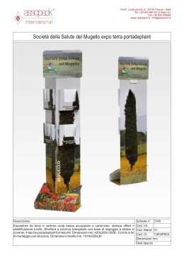
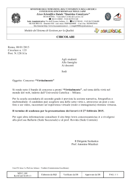
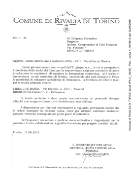
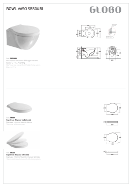
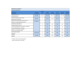
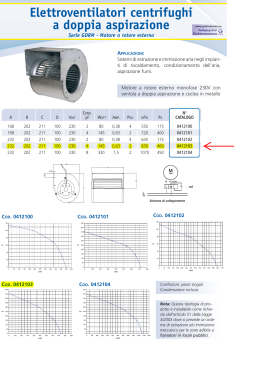
Pag. 1 di 20
ISTRUZIONI PER L'USO E L’INSTALLAZIONE
INSTRUCTIONS POUR L'UTILISATION ET L’INSTALLATION
OPERATING AND INSTALLATION INSTRUCTIONS
BETRIEBS- UND INSTALLATIONSANWEISUNGEN
Operatore per Serrande e Portoni Sezionali Industriali - Opérateur pour Grilles et Portes Sectionnelles Industrielles
Operator for Industrial Shutters and Sectional Gates - Torantriebe für die Automation von Rolläden und Sektionaltoren
Mod.
SIDE
Misure in mm - Mesures en mm - Measurements in mm - Abmessungen in mm
I
IMPORTANTI ISTRUZIONI PER LA SICUREZZA
ATTENZIONE - É IMPORTANTE PER LA SICUREZZA DELLE PERSONE
CHE VENGANO SEGUITE TUTTE LE ISTRUZIONI
CONSERVARE CON CURA QUESTE ISTRUZIONI
1° - Tenete i comandi dell'automatismo (pulsantiera, telecomando etc.) fuori dalla portata dei
bambini. I comandi devono essere posti ad un’altezza minima di 1,5mt dal suolo e fuori dal
raggio d’azione delle parti mobili.
2° - Effettuare le operazioni di comando da punti ove l'automazione sia visibile.
3° - Utilizzare i telecomandi solo in vista dell'automazione.
4° - Prima di eseguire qualsiasi operazione di installazione, regolazione, manutenzione
dell’impianto, togliere la tensione agendo sull’apposito interruttore magnetotermico collegato
a monte dello stesso.
5° - Avvertenze: Sulle altre misure di Protezione contro rischi attinenti l'installazione o
l'utilizzazione del Prodotto vedi, a completamento di questo libretto di Istruzioni, le
Avvertenze RIB allegate.
Qualora queste non siano pervenute chiederne l'immediato invio all'Ufficio Commerciale RIB.
LA DITTA RIB NON ACCETTA NESSUNA RESPONSABILITÀ per eventuali danni provocati
dalla mancata osservanza nell'installazione delle norme di sicurezza e le leggi attualmente in
vigore.
F
INSTRUCTIONS IMPORTANTES POUR LA SECURITE
IL EST IMPORTANT POUR LA SECURITE DES PERSONNES
DE SUIVRE ATTENTIVEMENT TOUTES INSTRUCTIONS
GARDER MODE D’EMPLOI
1° - Gardez les commandes de l'automatisme (boutons poussoirs, télécommande etc.) hors
de la portée des enfants. Les commandes doivent être placées au minimum à 1,5 m du
sol, et hors de rayon d’action des pièces mobiles.
2° - Il faut donner les commandes d'un lieu, où on peut voir la porte.
3° - Il faut utiliser les émetteurs seulement si on voit la porte.
4° - Avant d’exécuter quelconques opérationd’installation, réglage, entrietien de l’installation,
couper la tension avec l’interrupteur magnétothermique approprié connecté en amont.
5° - Avertissements: Sur les autres mesures de Protection contre les risques relatifs a
l'installation ou l'utilisation du Produit, voir, à titre de complément de ce livret
d'instructions, les Avertissements RIB ci-jointes. Dans le cas où celles-ci ne vous
seraient pas parvenues, en demander l'envoi immédiat au Bureau d’Exportation de RIB.
L'ENTREPRISE R.I.B. N'ACCEPTE AUCUNE RESPONSABILITÉ pour des dommages
éventuels provoqués par le manque d'observation lors de l'installation des normes de
sécurité et lois actuellement en vigueur.
IMPORTANT SAFETY INSTRUCTIONS
GB
WARNING - IT IS IMPORTANT FOR THE
SAFETY OF PERSONS TO FOLLOW ALL INSTRUCTIONS
SAVE THESE INSTRUCTIONS
1° - Keep the automatic control (push-button, remote control, etc) out of the reach of
children. The control systems must be installed at a minimum hight of 1.5m from
the ground surface and not interfere with the mobile parts.
2° - Command pulses must be given from sites, where you can see the gate.
3° - Use transmitters only if you can see the gate.
4° - Before starting any installation and operation or maintenance work make sure to
cut off power supply by turning the general magnetothermic switch off.
5° - Warnings: when you have finished reading this instruction booklet, please refer to
the RIB instructions attached for the other precautionary measures against risks
connected with the installation or use of the product. If you have not received
these, ask RIB Export Office to send them immediately.
R.I.B. IS NOT LIABLE for any damage caused by not following the safety regulations
and laws at present in force not being observed during installation.
D
WICHTIGE ANWEISUNGEN FÜR DIE SICHERHEIT
ACHTUNG - UM DIE SICHERHEIT VON PERSONEN VOLLKOMMEN
GARANTIEREN ZU KöNNEN, IST ES WICHTIG, DASS ALLE
INSTALLATIONSVORSCHRIFTEN BEACHTET WERDEN
1° - Bewahren Sie die Geräte für die automatische Bedienung (Drucktaster, Funksender,
u.s.w.) an einem für Kinder unzugänglichen Platz auf. Die Steuerungen müssen auf
einer Mindesthöhe von 1,5 m angebracht werden und sich ausserhalb der Raumes
der bewegenden Teile befinden.
2° - Die automatische Steuerung darf nur bedient werden, wenn das Tor sichtbar ist.
3° - Die Funksender nur benützen, wenn das Tor sichtbar ist.
4° - Bevor Sie eine Installation oder Wartungsarbeit an der Anlage durchführen, müssen
Sie kontrollieren, dass die Anlage spannungsfrei geschaltet ist.
5° - Achtung: Für weitere Schutzmaßnahmen im Rahmen der Installation und Anwendung
der Produkte siehe die beiliegenden RlB-Sicherheitshinweise, die diese
Gebrauchsanleitung ergänzen. Sollten Sie diese nicht erhalten haben, fordern Sie sie
bitte sofort bei der RlB Exportabteilung an.
R.I.B. HAFTET NICHT für eventuelle Schäden, die bei der Installation durch
Nichtbeachtung der jeweils gültigen Sicherheitsvorschriften entstehen.
Pag. 2 di 20
IMPORTANTI ISTRUZIONI DI SICUREZZA
PER L’INSTALLAZIONE
I
ATTENZIONE - UNA SCORRETTA INSTALLAZIONE PUÓ PORTARE A DANNI RILEVANTI
SEGUIRE TUTTE LE ISTRUZIONI PER UNA CORRETTA INSTALLAZIONE
1° - Questo libretto d'istruzioni è rivolto esclusivamente a del personale specializzato che sia a
conoscenza dei criteri costruttivi e dei dispositivi di protezione contro gli infortuni per i cancelli, le
porte e i portoni motorizzati (attenersi alle norme e alle leggi vigenti).
2° - Se non é previsto nella centralina elettrica, installare a monte della medesima un'interruttore di tipo
magnetotermico (onnipolare con apertura minima dei contatti pari a 3mm) che riporti un marchio di
conformità alle normative internazionali.
3° - Per la sezione ed il tipo dei cavi la RIB consiglia di utilizzare un cavo di tipo NPI07VVF con sezione
minima di 1,5mm2 e comunque di attenersi alla norma IEC 364 e alle norme di installazione vigenti
nel proprio Paese.
F
IMPORTANT SAFETY INSTRUCTION
FOR INSTALLATION
GB
WARNING -INCORRECT INSTALLATION CAN LEAD TO SEVERE INJURY
FOLLOW ALL INSTALLATION INSTRUCTIONS
1° - This instruction booklet is exclusively dedicated to specialized staff who are aware of the
construction criteria and of the accident prevention protection devices for motorized gates and
doors (according to the current regulations and laws).
2° - To maintain electrical parts safely it is advisable to equip the installation with a differential thermal
magnetic switch (onnipolar with a minimum opening of the contacts of 3mm) and must comply
with the international rules.
3° - As for electric cable type and section RIB suggests cable type <HAR> with minimum section of
1,5mm2 and however respect IEC 364 rule and general national security regulations.
IMPORTANT MODE D’EMPLOI DE SECURITE
POUR L’INSTALLATION
WICHTIGE SICHERHEITSVORSCHRIFTEN
FÜR DIE INSTALLATION
D
ACHTUNG - EINE FALSCHE INSTALLATION KANN ZU BEDEUTENDE SHADEN FÜHREN.
FÜR EINE KORREKTE ANLAGE ALLE ANWEISUNGEN BEFOLGEN
1° - Diese Montageanweisung ist ausschließlich für geschultes Fachpersonal bestimmt, das
mit den Montagevorschriften und den Schutzvorrichtungen zur Verhinderung von Unfällen bei
motorisierten Toren vertraut ist (nach den aktuellen Normen und Gesetzen).
2° - Für die Wartung der elektrischen Teile ist es ratsam, zwischen der Anlage und dem
Netzanschluß einen magnetisch-thermischen Differenzialschalter (mit Mindestöffnung aller
Kontakte von 3 mm) zu montieren, der alle internationalen Normen entspricht.
3° - Für den Kabelquerschnitt und die Kabeltypen halten Sie sich an den Normen IEC 364 (MindestKabelquerschnitt von 1,5 mm2 mit der Bezeichnung <HAR>) und für die Montage an die Normen
des jeweiligen Landes.
ATTENTION - UNE INSTALLATION INCORRECTE PEUT CAUSER DE GRANDS DOMMAGES
SUIVRE TOUTES INSTRUCTIONS POUR UNE CORRECTE INSTALLATION
1° - Ce manuel d'instruction est adressé seulement au personnel specialisé qui a une
connaissance des critères de construction et des dispositifs de protection contre les accidents en ce
qui concerne les portails, les portes et les portes cochères motorisées (suivre les normes et les lois
en vigueur).
2° - A fin de procéder à l'entretien des parties électriques, connecter à l'installation un disjoncteur
differentiel magneto thermique (qui disconnait toutes les branchements de la ligne avec ouverture
min. des branchements de 3 mm ) et qui soit conforme aux normes internationales.
3° - Pour la section et le type des câbles à installer nous vous conseillons d’utiliser un cable <HAR>
avec une section min de 1,5 mm2 en respectant quand même la norme IEC 364 et les normes
nationales d'installation.
I
CARATTERISTICHE TECNICHE MOTORIDUTTORE
F
CARACTERISTIQUES TECHNIQUES MOTOREDUCTEUR
La serie di operatori SIDE è da utilizzarsi per la movimentazione di
serrande industriali non bilanciate.
La serie SIDE è dotata di dispositivo paracadute incorporato. Altre applicazioni devono
essere espressamente autorizzate dalla RIB srl.
L’installatore deve essere certo che il palo sia fissato saldamente su entrambi i supporti.
Dopo aver fatto ciò l’installazione deve essere eseguita a seconda del tipo serranda.
La RIB raccomanda l’utilizzo di accessori meccanici ed elettrici RIB per assicurare
un’installazione senza problemi.
N.B.: È obbligatorio uniformare le caratteristiche della serranda alle norme e leggi
vigenti.
GB
GEARMOTOR TECHNICAL CHARACTERISTICS
D
TECHNISCHE DATEN GETRIEBEMOTOR
The SIDE series is intended for the operating on roller shutters and is
complete of an integral safety stop.
Other applications have to be expressly permitted by RIB srl.
The fitter must make sure, that the drive is mounted either on a console or torque
supporting plate with sufficient strenght. After this the installation must be taken into
consideration according to the various door types.
RIB recommends the RIB mechanical and electrical accessories which are suited for
these drives to ensure problem-free installation.
ATTENTION: It is compulsory to conform the roller shutter door characteristics to the
current regulations and laws.
Le motoréducteurs SIDE sont prévue pour la manoeuvre de portes
sectionelles et sont dotée de stop chute intégré.
Les autres applications doivent être autorisées par la société RIB srl.
Le monteur doit veiller à ce que la motorisation soit installée sur une console ou un support
stable et anti-vibration.
Procéder aux étapes de montage correspondant aux différents types de porte pour mettre le
moteur en service. Utiliser les accessories mécaniques et électriques RIB, adaptés et
homologués à ces motoréducteurs.
N.B.: Il est obligatoire d’adapter les caracteristiques du rideau aux normes et lois en
vigueur.
Der SIDE ist für den Antrieb von Sektionaltoren vorgesehen and ist komplete
mit eingebauter Fangvorrichtung. Andere Anwendungen sind nur nach Genehmigung durch
die Firma RIB srl zulässig. Der Monteur hat dafür Sorge zu tragen, daß der Antrieb auf einer
Konsole oder Drehmomentstütze mit ausreichender Festigkeit, möglichst
schwingungsgedämpft, montiert wird.
Danach sind die den unterschiedlichen Tortypen entsprechenden Montageschritte zur
Inbetriebnahme der Antriebe zu beachten! RIB empfiehlt zur problemlosen Montage das auf
diese Antriebe abgestimmte und geprüfte mechanische und elektrische RIB-Zubehör.
ACHTUNG: Man ist verpflichtet die Eigenschaften des Rolltores mit den Gesetzen und
Normen in Einklang zu bringen.
CARATTERISTICHE TECNICHE
TECHNICAL DATA
CARACTERISTIQUES TECHNIQUES
TECHNISCHE DATEN
Coppia massima - Couple maxi
Max torque - Max Drehmoment
Nm
Velocità di rotazione - Vitesse
Speed - Antriebsdrehzahl
rpm
15 (for roller shutters) - 23 (for sectional doors)
Limite dei finecorsa
Limit switch range
rev
24
Capacité des fins de course
Endschalterbereich
Alimentazione e frequenza CEE
EEC Power supply
Alimentation et frequence CEE
Stromversorgung EEC
Potenza motore - Puissance moteur
Motor capacity - Motorleistung
W
Assorbimento - Courant nominal
Power absorbed-Stromaufnahme
A
2
2,9
2,8
4,2
4,6
n° cicli - Nbre de cycles
No. cycles - Anzahl Zyklen
n°
9 - 96s/2s
9 - 96s/2s
9 - 96s/2s
9 - 96s/2s
9 - 96s/2s
Peso motore - Poids moteur
Motor weight - Motorgewicht
Kg
15
16
28HK - 33LK
32HK - 37LK
43HK - 48LK
Rumorosità - Bruit
Noise- Geräusch
db
<70db
Grado di protezione
Protection
IP
54
Indice de protection
Schutzart
SIDE170
170
SIDE250
SIDE450
SIDE600
SIDE750
250
450
600
750
400V ~ 50Hz 3P
600
850
1100
1500
2200
Pag. 3 di 20
Ø Palo - Ø tube d’enroulement - Tube Ø - Rohrdurchmesser
Spessore palo - Epaisseur du tube - Tube thickness - Rohrwanddicke
Peso palo al mt - Poids au mètre - Tube weight per m - Rohrgewicht je m
Lunghezza palo - Longueur du tube d’enroulement
Tube lenght - Rohrlänge
mm
mm
Kg
2m
3m
4m
5m
6m
7m
8m
9m
10 m
11 m
12 m
13 m
14 m
15 m
16 m
TABELLA DI VELOCITÀ E CARICO
PER SERRANDE INDUSTRIALI
NON BILANCIATE
TABLEAU DES POIDS ET VITESSES
POUR RIDEAUX INDUSTRIELLES
NON COMPENSÉES
LOAD AND SPEED TABLE
FOR NOT BALANCED
INDUSTRIAL ROLLER SHUTTERS
BELASTUNGSTABELLE
FÜR NICHT ENTLASTET
ROLLÄDEN VON INDUSTRIEANLAGEN
Modello
Type
Model
Typ
Diametro del rullo avvolgitore
Diamètre du tube d’enroulement
Shaft diameter
Rohrdurchmesser
Ø mm
Velocità iniziale
Vitesse initiale
Initial speed
Anfangs-geschwindigkeit
m/s
SIDE
170
100
133
159
168
193
219
100
133
159
168
193
219
133
159
168
193
219
244
267
298
324
133
159
168
193
219
244
267
298
324
133
159
168
193
219
244
267
298
324
0,08
0,10
0,12
0,13
0,15
0,17
0,08
0,10
0,12
0,13
0,15
0,17
0,10
0,12
0,13
0,15
0,17
0,19
0,20
0,23
0,25
0,10
0,12
0,13
0,15
0,17
0,19
0,20
0,23
0,25
0,10
0,12
0,13
0,15
0,17
0,19
0,20
0,23
0,25
15rpm
SIDE
250
15rpm
SIDE
450
15rpm
Questi dati non sono costrittivi e servono per
selezionare il giusto operatore a seconda
della serranda avvolgibile che si vuole
utilizzare.
I dati sono comprensivi di una perdita del
20% dovuta ad attrito.
Ces donnés sont indiquées pour selectionner
l’operateur le mieux adapté au rideau. Le
poids indiqué prend en compte une perte de
20% due aux frottements.
These data are not binding and relate to
complete roller shutter doors and grills.
They include 20% loss for friction.
Diese Angaben beziehen sich auf das
komplette Rolltor: 20% Reibung sind
108
133
159
168,3
178
193,7 219,1
3,6
4
4,5
4,5
5
5,4
5,9
9,33
12,8
17,1
18,2
21,3
25
31
Forza di sostentamento del palo (N) - Charge max. du tube
Max tube load (in N) - Gewichtskraft des Rolltoores (in N)
9315
14610 20050 20180 21570
6080
9560
13530 14210 14900
4650
6865
9800 10950 12110 19120
2745
4900
7450
8530
9610 14510 20930
1665
3040
5400
6380
7350 11570 16666
1960
3680
4280
4900
9315 13725
1080
2450
2790
3140
6250 11030
1470
1710
1960
4910
7650
980
2940
5150
1715
3430
1960
SIDE
600
15rpm
SIDE
750
15rpm
244,5
6,3
37,1
20940
17155
14360
11325
8200
5690
3824
2210
267
7,1
45,6
24510
20590
17300
13480
9610
6865
4510
2696
298,5
8
57,1
323,9
8
62,1
25145
20600
18040
14310
10345
7350
4900
2745
1960
25300
21570
17155
13530
9800
6860
5490
Peso max in Kg della serranda c/profilo=19mm e alto:
Poids (Kg) du rideau avec épaisseur 19mm et haut:
Shutter weight if profile 19mm and height:
Zuglast (Kg) wenn profil 19mm, Torhöhe:
H=3m
H=5m
H=8m
205
174
157
152
136
121
302
256
231
224
200
178
462
416
403
360
321
290
267
241
223
616
555
537
480
428
387
356
321
297
738
665
644
577
514
465
427
385
356
175
158
147
141
129
118
288
250
216
208
190
174
420
389
375
342
314
290
267
241
223
560
518
500
456
418
387
356
321
297
673
622
600
547
502
465
427
385
356
148
139
131
129
120
113
213
201
190
177
166
368
348
342
319
299
276
258
238
222
491
464
456
425
398
368
345
318
297
590
557
547
510
478
442
414
381
356
Pag. 4 di 20
SERRANDA INDUSTRIALE
CON MOTORE CHE TRAINA E SUPPORTA IL PALO
RIDEAU MÉTALLIQUE/GRILLE INDUSTRIELLE
AVEC ETRAÎNEMENT DIRECT SUR LE TUBE
INDUSTRIAL ROLLER SHUTTER
WITH DRIVE MOUNT DIRECTLY THE SHAFT
TORANLAGE MIT DIREKTLAGERUNG IM ANTRIEB
SIDE 170 LK
SIDE 250 LK
cod. AA81502
cod. AA81505
Centrale di comando MINI JS
Centrale di comando AQM111
SIDE 170 HK
SIDE 250 HK
SIDE 450 HK
SIDE 600 HK
SIDE 750 HK
Coffret électrique MINI JS
Coffret électrique AQM111
ACCESSORI PER SIDE 170 / 250
ACCESSOIRES POUR SIDE 170 / 250
(1/a) Squadra di ancoraggio e supporto Equerre d’ancrage et support
(2) Palo di traino lato motore
Arbre d’etrainement côté moteur
(3) Adattatore tra motore e squadra
Socle moteur
d’ancoraggio e supporto
(4) Supporto UCP206
Palier à semelle UCP206
(5) Palo di traino lato UCP
Arbre d’etraînement côté UCP
(6) 2 - Vite M12x50 per fissaggio UCP 2 - Vis M12x50 pour palier
(7) dischi per palo:
Flasques:
Ø 99
Ø 99
Ø 125
Ø 125
Ø 149
Ø 149
Ø 159
Ø 159
Ø 180
Ø 180
Ø 205
Ø 205
ACCESSORI PER SIDE 450
ACCESSOIRES POUR SIDE 450
(1/b) Squadra di ancoraggio e supporto Equerre d’ancrage et support
(2) Palo di traino lato motore
Arbre d’etrainement côté moteur
(3) Adattatore tra motore e squadra
Socle moteur
d’ancoraggio e supporto
(4) Supporto UCP208
Palier à semelle UCP208
(5) Palo di traino lato UCP
Arbre d’etraînement côté UCP
(6) 2 - Vite M16x60 per fissaggio UCP 2 - Vis M16x60 pour palier
(7) dischi per palo:
Flasques:
Ø 159
Ø 159
Ø 180
Ø 180
Ø 205
Ø 205
Ø 230
Ø 230
Ø 250
Ø 250
Ø 280
Ø 280
Ø 305
Ø 305
ACCESSORI PER SIDE600/750
ACCESSOIRES POUR SIDE 600/750
(1/b) Squadra di ancoraggio e supporto Equerre d’ancrage et support
(2) Palo di traino lato motore
Arbre d’etrainement côté moteur
(3) Adattatore tra motore e squadra
Socle moteur
d’ancoraggio e supporto
(4) Supporto UCP209
Palier à semelle UCP209
(5) Palo di traino lato UCP
Arbre d’etraînement côté UCP
(6) 2 - Vite M16x60 per fissaggio UCP 2 - Vis M16x60 pour palier
(7) dischi di
Flasques:
Ø 159
Ø 159
Ø 180
Ø 180
Ø 205
Ø 205
Ø 230
Ø 230
Ø 250
Ø 250
Ø 280
Ø 280
Ø 305
Ø 305
Solo per SIDE 170/250
Uniquement pour les modèles 175/250
Only for SIDE170/250
Nur für SIDE 170/250
cod. AA81500
cod. AA81503
cod. AA81506
cod. AA81509
cod. AA81512
A
B
C
SIDE 170/250
120
43
77
SIDE 450
144
49
95
SIDE 600/750
144
54
90
LK = con catenella di sblocco
LK = avec chaine pour deblocage
LK = with chain to release
LK = mit leichter Kette
HK = con manovella di sblocco
HK = avec manivelle pour déblocage
HK = with hand crank to release
HK = mit Handkurbel
Control board MINI JS
Control board AQM111
Steuerung MINI JS
Steuerung AQM111
ABQM080
ABQM111
ACCESSORIES FOR SIDE 170 / 250
Ancorage and support square
Drive Shaft motor side
Adaptor between motor and support
ZUBEHÖR FÜR SIDE 170 / 250
Wandkonsole
Einschweißwelle Antriebsseite
Fuß - Adapter
ACG4500
ACG4579
Pedestal Bearing UCP206
Drive Shaft UCP side
2 - screws M12x50 to fix UCP
Welding discs:
Ø 99
Ø 125
Ø 149
Ø 159
Ø 180
Ø 205
Stehpendellager UCP206
Einschweißwelle Gegenseite
Befestigungsschrauben
Einschweißronde:
Ø 99
Ø 125
Ø 149
Ø 159
Ø 180
Ø 205
ACCESSORIES FOR SIDE 450
Ancorage and support square
Drive Shaft motor side
Adaptor between motor and support
ZUBEHÖR FÜR SIDE 450
Wandkonsole
Einschweißwelle Antriebsseite
Fuß - Adapter
Pedestal Bearing UCP208
Drive Shaft UCP side
2 - screws M16x60 to fix UCP
Welding discs:
Ø 159
Ø 180
Ø 205
Ø 230
Ø 250
Ø 280
Ø 305
Stehpendellager UCP208
Einschweißwelle Gegenseite
Befestigungsschrauben
Einschweißronde
Ø 159
Ø 180
Ø 205
Ø 230
Ø 250
Ø 280
Ø 305
ACCESSORIES FOR SIDE 600/750
Ancorage and support square
Drive Shaft motor side
Adaptor between motor and support
ZUBEHÖR FÜR SIDE 600/750
Wandkonsole
Einschweißwelle Antriebsseite
Fuß - Adapter
Pedestal Bearing UCP209
Drive Shaft UCP side
2 - screws M16x60 to fix UCP
Welding discs:
Ø 159
Ø 180
Ø 205
Ø 230
Ø 250
Ø 280
Ø 305
Stehpendellager UCP209
Einschweißwelle Gegenseite
Befestigungsschrauben
Einschweißronde
Ø 159
Ø 180
Ø 205
Ø 230
Ø 250
Ø 280
Ø 305
ACG4502
ACG4590
ACG4504
ACG4505
ACG4506
ACG4507
ACG4508
ACG4509
ACG4510
ACG4511
ACG4520
ACG4521
ACG4522
ACG4591
ACG4524
ACG4561
ACG4525
ACG4526
ACG4527
ACG4528
ACG4529
ACG4530
ACG4531
ACG4520
ACG4532
ACG4522
ACG4592
ACG4534
ACG4561
ACG4525
ACG4526
ACG4527
ACG4528
ACG4529
ACG4530
ACG4531
- Se la quota A=110mm invece di 120mm, allora deve essere usato l’accessorio ACG4567 al posto dell’accessorio ACG4502
- en présence de la dimension A=110 mm, au lieu de 120 mm, on doit alors utiliser l'accessoire ACG4567 à la place de l'accessoire ACG4502
- If level A=110mm, instead of 120mm, it is necessary to use accessory ACG4567 in place of accessory ACG4502
- Wenn Maß A = 110 mm anstatt 120 mm, muß das Zubehörteil ACG4567 an Stelle des Zubehörteils ACG4502 eingesetzt werden.
Pag. 5 di 20
Fig.1/a
cod. ACG4500
Fig.1/b
cod. ACG4520
Fig. 2
cod. ACG4579
cod. ACG4521
cod. ACG4532
Fig. 3
cod. ACG4502
cod. ACG4522
Fig.4
UCP206 cod. ACG4590
UCP208 cod. ACG4591
UCP209 cod. ACG4532
Fig.5
cod. ACG4504
cod. ACG4524
cod. ACG4534
Fig.6
cod.ACG4505
cod.ACG4561
Fig.8
cod.ACG4567
Fig. 7
Codice
Code
Code
Artikelnummer
ACG4506
ACG4507
ACG4508
ACG4509
ACG4525
ACG4510
ACG4526
ACG4511
ACG4527
ACG4528
ACG4529
ACG4530
ACG4531
Ø esterno
Ø externe
external Ø
Außendurchmesser
99
125
149
159
159
180
180
205
205
230
250
280
305
Ø interno
Ø interne
internal Ø
Innendurchmesser
42
42
42
42
50
42
50
42
50
50
50
50
50
spessore disco
épaisseur du rondelle pour axe
Welding disc
Wanddicke Einschweißbronde
6
6
6
6
6
6
6
6
6
8
8
8
8
Ø palo
Ø du tube
Shaft Ø
Rohrdurchmesser
108
133
159
168,3
168,3
193,7
193,7
219,1
219,1
244,5
267
298,5
323,9
spessore palo
épaisseur du tube
Thickness Shaft
Rohrwanddicke
3,6
4,0
4,5
4,5
4,5
5,4
5,4
5,9
5,9
6,3
7,1
8
8
Pag. 6 di 20
SERRANDA INDUSTRIALE CON SUPPORTI FLOTTANTI
(per ridurre le spazio tra palo e guida della serranda quando la serranda è
chiusa)
GRILLES INDUSTRIELS AVEC MONTAGE SUR PALIERS FLOTTANTS
(pour réduire l’ouverture entre le linteau et le tube d’enroulement quand la
porte est fermée)
INDUSTRIAL SHUTTER ON FLOATING BARRIERS
(to reduce space between lintel and barrel when door is closed)
ANROLLSYSTEM FÜR TORE
SIDE 170 LK
SIDE 250 LK
cod. AA81502
cod. AA81505
SIDE 170 HK
SIDE 250 HK
cod.AA81500
cod.AA81503
LK = con catenella di sblocco
LK = avec chaîne pour déblocage
LK = with chain to release
LK = mit leichter Kette
HK = con manovella di sblocco
HK = avec manivelle pour déblocage
HK = with hand crank to release
HK = mit Handkurbel
Centrale di comando MINI JS
Centrale di comando AQM111
Coffret électrique MINI JS
Coffret électrique AQM111
Control board MINI JS
Control board AQM111
Steuerung MINI JS
Steuerung AQM111
ACCESSORI PER SIDE170 / 250
(1) Squadra di ancoraggio e supporto
con rulli d’adattamento
(2) Palo di traino lato motore
(3) Supporto lato motore
(4) Palo di traino lato cuscinetto
(5) Supporto con cuscinetto
dischi di
Ø 99
Ø 125
Ø 149
Ø 159
Ø 180
Ø 205
ACCESSOIRES POUR SIDE 170/250
Consoles avec paliers flottants
ACCESSORIES FOR SIDE 170/250
Console with floating barriers
ZUBEHÖR FÜR SIDE 170 / 250
Anrollkonsole
Axe côté moteur
Rondelles côte moteur
Axe côté opposé
Rondelles avec
Flasques
Ø 99
Ø 125
Ø 149
Ø 159
Ø 180
Ø 205
Drive Shaft actuator side
Support actuator side
Drive Shaft bearing side
Support with bearing
Welding discs:
Ø 99
Ø 125
Ø 149
Ø 159
Ø 180
Ø 205
Einschweißwelle Antriebsseite
Halter antriebseite
Einschweißwelle Gegenseite
Halter mit Lagerschale
Einschweißronden:
Ø 99
Ø 125
Ø 149
Ø 159
Ø 180
Ø 205
ABQM080
ABQM111
ACG4578
ACG4501
ACG4580
ACG4581
ACG4582
ACG4506
ACG4507
ACG4508
ACG4509
ACG4510
ACG4511
Fig. 1
cod. ACG4578
Fig. 2
cod. ACG4501
Fig. 3
cod.ACG4580
Fig. 4
cod.ACG4581
Fig. 5
cod. ACG4582
Pag. 7 di 20
SERRANDE INDUSTRIALI LK CON TRAINO A CATENA
GRILLES INDUSTRIELLES LK
AVEC MOUVEMENT A CHAINE
INDUSTRIAL SHUTTER LK
WITH CHAIN MOVEMENT
TORANLAGE LK MIT KETTENANTRIEB
SIDE 170/250
A
B
C
49
71
100
SIDE 450
57
93
150
SIDE 600/750
63
117
180
SIDE 170 LK
SIDE 250 LK
cod. AA81502
cod. AA81505
LK = con catenella di sblocco
LK = avec chaine pour deblocage
LK = with chain to release
LK = mit leichter kette
Centrale di comando MINI JS
Centrale di comando AQM111
Coffret électrique MINI JS
Coffret électrique AQM111
Control board MINI JS
Control board AQM111
Steuerung MINI JS
Steuerung AQM111
ACCESSORI PER SIDE 170/250
LATO MOTORE
(1/a) 3 Squadre di ancoraggio e supporto
(2) Adattatore tra motore e squadra
d’ancoraggio e supporto
(3) Albero di traino corto per motore
(4) Palo di traino lato motore
(5) UCP208
(6) Ingranaggio catena Z=15
(6) Ingranaggio catena Z=30
(7) Catena lunga 1,5mt
(8) 6 Viti M12x50
(11) dischi di:
Ø 159
Ø 180
Ø 205
Ø 230
Ø 250
Ø 280
Ø 305
ACCESSOIRES POUR SIDE 170/250
CÔTÉ ELETROREDUCTEUR
3 Equerres d’ancrage et support
Socle moteur
ACCESSORIES FOR SIDE 170/250
ACTUATOR SIDE
3 Ancorage and support squares
Adaptor between motor and support
ZUBEHÖR FÜR SIDE 170/250
ANTRIEBSEITE
3 Wandkonsolen
Fuß - Adapter
Arbre d’etrainement bref pour électrored.
Arbre d’etrainement côté électrored.
UCP208
Engranage chaîne Z=15
Engranage chaîne Z=30
Chaîne 1,5m
6 Vis M12x50
Flasques:
Ø 159
Ø 180
Ø 205
Ø 230
Ø 250
Ø 280
Ø 305
Drive Shaft short for actuator
Drive Shaft actuator side
UCP208
Chain gear Z=15
Chain gear Z=30
Chain 1,5m
6 Screws M12x50
Renstrain Cap:
Ø 159
Ø 180
Ø 205
Ø 230
Ø 250
Ø 280
Ø 305
Kupplungsbolzen
Einschweißwelle
Stehpendellager UCP208
Kettenrad Z=15
Kettenrad Z=30
Kette 1,5 m
6 Befestigungsschrauben M12x50
Einschweißronden:
Ø 159
Ø 180
Ø 205
Ø 230
Ø 250
Ø 280
Ø 305
PARACHUTE SIDE
Ancorage and support square
Parachute TS3-RD
Drive Shaft parachute side
2 Screws M16x40 to fix parachute
Renstrain Cap:
Ø 159
Ø 180
Ø 205
Ø 230
Ø 250
Ø 280
Ø 305
GEGENSEITE
Wandkonsole
Abrollsicherung
Einschweißwelle
2 Befestigungsschrauben M16x40
Einschweißronden:
Ø 159
Ø 180
Ø 205
Ø 230
Ø 250
Ø 280
Ø 305
LATO PARACADUTE
CÔTÉ PARACHUTE
(1/a) Squadra di ancoraggio e supporto
Equerre d’ancrage et support
(9) Paracadute TS3-RD
Parachute TS3-RD
(10) Palo di traino lato paracadute
Arbre d’etrainement côté parachute
(8) 2 Vite M16x40 per fissaggio Paracadute 2 Vis M16x40 pour fixer parachute
(11) dischi di:
Flasques:
Ø 159
Ø 159
Ø 180
Ø 180
Ø 205
Ø 205
Ø 230
Ø 230
Ø 250
Ø 250
Ø 280
Ø 280
Ø 305
Ø 305
Fig.1
cod. ACG4500
Fig. 2
ABQM080
ABQM111
ACG4500
ACG4541
ACG4542
ACG4543
ACG4591
ACG4545
ACG4546
ACG4547
ACG4505
ACG4525
ACG4526
ACG4527
ACG4528
ACG4529
ACG4530
ACG4531
ACG4500
ACG4550
ACG4551
ACG4552
ACG4525
ACG4526
ACG4527
ACG4528
ACG4529
ACG4530
ACG4531
cod. ACG4541
Pag. 8 di 20
cod. ACG4543
Fig. 3
cod. ACG4542
Fig.4
Fig. 5
UCP208 cod. ACG4591
Fig.6
cod. ACG4545
cod. ACG4546
Fig.8
cod. ACG4505
cod. ACG4552
Fig.7
cod. ACG4547
Fig.9
cod. ACG4550
cod. ACG4551
Fig. 10
Fig. 11
Codice
Code
Code
Artikelnummer
ACG4525
ACG4526
ACG4527
ACG4528
ACG4529
ACG4530
ACG4531
Ø esterno
Ø externe
external Ø
Außenfurchmesser
159
180
205
230
250
280
305
Ø interno
Ø interne
internal Ø
Innendurchmesser
50
50
50
50
50
50
50
spessore disco
espesseur du rondelle pour axe
Welding disc
Einschweßbrondenwanddicke
6
6
6
8
8
8
8
Ø palo
Ø du tube
Shaft Ø
Rohrdurchmesser
168,3
193,7
219,1
244,5
267
298,5
323,9
spessore palo
espesseur du tube
Thickness Shaft
Rohrwanddicke
4,5
5,4
5,9
6,3
7,1
8
8
Pag. 9 di 20
SERRANDE INDUSTRIALI HK CON TRAINO A CATENA
GRILLES INDUSTRIELLES HK
AVEC MOUVEMENT A CHAINE
INDUSTRIAL SHUTTER HK
WITH CHAIN MOVEMENT
TORANLAGE HK MIT KETTENANTRIEB
SIDE 170/250
A
B
C
49
71
100
SIDE 450
57
93
150
SIDE 600/750
63
117
180
SIDE 170 HK
SIDE 250 HK
SIDE 450 HK
SIDE 600 HK
SIDE 750 HK
cod. AA81500
cod. AA81503
cod. AA81506
cod. AA81509
cod. AA81512
HK = con manovella di sblocco
HK = con manovella di sblocco
HK = with handle to release
HK = mit Handkurbel
Centrale di comando MINI JS
Centrale di comando AQM111
Coffret électrique MINI JS
Coffret électrique AQM111
Control board MINI JS
Control board AQM111
Steuerung MINI JS
Steuerung AQM111
ACCESSORI PER SIDE 170/250
LATO MOTORE
(1/a)Squadra di ancoraggio e supporto
(2) Piastra di fissaggio a parete
con motore in verticale (2x)
(3) Adattatore tra motore e sua piastra
(4) Albero di traino corto per motore
(5) Palo di traino lato motore
(6) UCP208
(7) Ingranaggio catena Z=15
(7) Ingranaggio catena Z=30
(8) Catena lunga 1,5mt
(9) 2 - Vite M12x50 per fissaggio UCP
(12) dischi di:
Ø 159
Ø 180
Ø 205
Ø 230
Ø 250
Ø 280
Ø 305
ACCESSOIRES POUR SIDE 170/250
CÔTÉ ELETROREDUCTEUR
Equerre d’ancrage et support
Socle moteur
ACCESSORIES FOR SIDE 170/250
ACTUATOR SIDE
Ancorage and support square
Adaptor between motor and support
ZUBEHÖR FÜR SIDE 170/250
ANTRIEBSEITE
Wandkonsole
Spannschiene (2x)
Adaptateur
Arbre d’etrainement bref pour électrored.
Arbre d’etrainement côté électrored.
UCP208
Engranage chaîne Z=15
Engranage chaîne Z=30
Chaîne 1,5m
Vis pour fixer UCP
Flasques:
Ø 159
Ø 180
Ø 205
Ø 230
Ø 250
Ø 280
Ø 305
Adaptor between actuator and supportFuß - Adapter
Drive Shaft short for actuator
Kupplungsbolzen
Drive Shaft actuator side
Einschweißwelle
UCP208
Stehpendellager UCP208
Chain gear Z=15
Kettenrad Z=15
Chain gear Z=30
Kettenrad Z=30
Chain 1,5m
Kette 1,5 m
Screws to fix UCP
Befestigungsschrauben
Renstrain Cap:
Einschweißronden:
Ø 159
Ø 159
Ø 180
Ø 180
Ø 205
Ø 205
Ø 230
Ø 230
Ø 250
Ø 250
Ø 280
Ø 280
Ø 305
Ø 305
LATO PARACADUTE
(1/a) Squadra di ancoraggio e supporto
(10) Paracadute TS3-RD
(11) Palo di traino lato paracadute
(9) Vite M16x40 per fissaggio Paracadute
(12) dischi di:
Ø 159
Ø 180
Ø 205
Ø 230
Ø 250
Ø 280
Ø 305
CÔTÉ PARACHUTE
Equerre d’ancrage et support
Parachute TS3-RD
Arbre d’etrainement côté parachute
Vis M16x40 pour fixer parachute
Flasques:
Ø 159
Ø 180
Ø 205
Ø 230
Ø 250
Ø 280
Ø 305
PARACHUTE SIDE
Ancorage and support square
Parachute TS3-RD
Drive Shaft parachute side
Screw M16x40 to fix parachute
Renstrain Cap:
Ø 159
Ø 180
Ø 205
Ø 230
Ø 250
Ø 280
Ø 305
GEGENSEITE
Wandkonsole
Abrollsicherung
Einschweißwelle
Befestigungsschrauben
Einschweißronden:
Ø 159
Ø 180
Ø 205
Ø 230
Ø 250
Ø 280
Ø 305
ACCESSORI PER SIDE 450
LATO MOTORE
(1/b)Squadra di ancoraggio e supporto
(2) Piastra di fissaggio a parete
con motore in verticale (x2)
(3) Adattatore tra motore e sua piastra
(4) Albero di traino corto per motore
(5) Palo di traino lato motore
(6) UCP210
(7) Ingranaggio catena Z=15
(7) Ingranaggio catena Z=30
(8) Catena lunga 1,5mt
(9) 2 - Vite M16x60 per fissaggio UCP
(12) dischi di:
Ø 230
Ø 250
Ø 280
Ø 305
ACCESSOIRES POUR SIDE 450
CÔTÉ ELETROREDUCTEUR
Equerre d’ancrage et support
Socle moteur
ACCESSORIES FOR SIDE 450
ACTUATOR SIDE
Ancorage and support square
Adaptor between motor and support
ZUBEHÖR FÜR SIDE 450
ANTRIEBSEITE
Wandkonsole
Spannschiene (2x)
Adaptateur
Arbre d’etrainement bref pour électrored.
Arbre d’etrainement côté électrored.
UCP210
Engranage chaîne Z=15
Engranage chaîne Z=30
Chaîne 1,5m
Vis pour fixer UCP
Flasques:
Ø 230
Ø 250
Ø 280
Ø 305
Adaptor between actuator and supportFuß - Adapter
Drive Shaft short for actuator
Kupplungsbolzen
Drive Shaft actuator side
Einschweißwelle
UCP210
Stehpendellager UCP210
Chain gear Z=15
Kettenrad Z=15
Chain gear Z=30
Kettenrad Z=30
Chain 1,5m
Kette 1,5 m
Screws to fix UCP
Befestigungsschrauben
Renstrain Cap:
Einschweißronden:
Ø 230
Ø 230
Ø 250
Ø 250
Ø 280
Ø 280
Ø 305
Ø 305
ABQM080
ABQM111
ACG4500
ACG4540
ACG4541
ACG4542
ACG4543
ACG4591
ACG4545
ACG4546
ACG4547
ACG4505
ACG4525
ACG4526
ACG4527
ACG4528
ACG4529
ACG4530
ACG4531
ACG4500
ACG4550
ACG4551
ACG4552
ACG4525
ACG4526
ACG4527
ACG4528
ACG4529
ACG4530
ACG4531
ACG4520
ACG4553
ACG4554
ACG4555
ACG4583
ACG4593
ACG4558
ACG4559
ACG4560
ACG4561
ACG4562
ACG4563
ACG4564
ACG4565
Pag. 10 di 20
LATO PARACADUTE
(1/b) Squadra di ancoraggio e supporto
(10) Paracadute TS4-RD
(11) Palo di traino lato paracadute
(9) Vite M16x40 per fissaggio Paracadute
(12) dischi di:
Ø 230
Ø 250
Ø 280
Ø 305
CÔTÉ PARACHUTE
Equerre d’ancrage et support
Parachute TS4-RD
Arbre d’etrainement côté parachute
Vis M16x40 pour fixer parachute
Flasques:
Ø 230
Ø 250
Ø 280
Ø 305
PARACHUTE SIDE
Ancorage and support square
Parachute TS4-RD
Drive Shaft parachute side
Screw M16x40 to fix parachute
Restrain Cap:
Ø 230
Ø 250
Ø 280
Ø 305
GEGENSEITE
Wandkonsole
Abrollsicherung
Einschweißwelle
Befestigungsschrauben
Einschweißronden:
Ø 230
Ø 250
Ø 280
Ø 305
ACCESSORI PER SIDE 600/750
ACCESSOIRES POUR SIDE 600/750
LATO MOTORE
CÔTÉ ELETROREDUCTEUR
(1/b)Squadra di ancoraggio e supporto (2x) Equerre d’ancrage et support (2x)
(2) Piastra di fissaggio a parete
Socle moteur
con motore in verticale
(3) Adattatore tra motore e sua piastra
Adaptateur
(4) Albero di traino corto per motore
Arbre d’etrainement bref pour électrored.
(5) Palo di traino lato motore
Arbre d’etrainement côté électrored.
(6) UCP211
UCP211
(7) Ingranaggio catena Z=15
Engranage chaîne Z=15
(7) Ingranaggio catena Z=30
Engranage chaîne Z=30
(8) Catena lunga 1,5mt
Chaîne 1,5m
(9) 2 - Vite M16x60 per fissaggio UCP
Vis pour fixer UCP
(12) dischi di:
Flasques:
Ø 250
Ø 250
Ø 280
Ø 280
Ø 305
Ø 305
ACCESSORIES FOR SIDE 600/750
ACTUATOR SIDE
Ancorage and support square (2x)
Adaptor between motor and support
ZUBEHÖR FÜR SIDE 600/750
ANTRIEBSEITE
Wandkonsole(2x)
Spannschiene (2x)
LATO PARACADUTE
(1/b) Squadra di ancoraggio e supporto
(10) Paracadute TS5-RD
(11) Palo di traino lato paracadute
(9) 2 - Vite M16x40 per Paracadute
(12) dischi di:
Ø 250
Ø 280
Ø 305
PARACHUTE SIDE
Ancorage and support square
Parachute TS5-RD
Drive Shaft parachute side
Screw M16x40 to fix parachute
Restrain Cap:
Ø 250
Ø 280
Ø 305
CÔTÉ PARACHUTE
Equerre d’ancrage et support
Parachute TS5-RD
Arbre d’etrainement côté parachute
Vis M16x40 pour fixer parachute
Flasques:
Ø 250
Ø 280
Ø 305
Adaptor between actuator and supportFuß - Adapter
Drive Shaft short for actuator
Kupplungsbolzen
Drive Shaft actuator side
Einschweißwelle
UCP211
Stehpendellager UCP211
Chain gear Z=15
Kettenrad Z=15
Chain gear Z=30
Kettenrad Z=30
Chain 1,5m
Kette 1,5 m
Screws to fix UCP
Befestigungsschrauben
Restrain Cap:
Einschweißronden:
Ø 250
Ø 250
Ø 280
Ø 280
Ø 305
Ø 305
GEGENSEITE
Wandkonsole
Abrollsicherung
Einschweißwelle
Befestigungsschrauben
Einschweißronden:
Ø 250
Ø 280
Ø 305
ACG4520
ACG4566
ACG4556
ACG4552
ACG4562
ACG4563
ACG4564
ACG4565
ACG4520
ACG4553
ACG4554
ACG4568
ACG4574
ACG4594
ACG4571
ACG4572
ACG4560
ACG4561
ACG4563
ACG4564
ACG4565
ACG4520
ACG4573
ACG4569
ACG4552
ACG4575
ACG4576
ACG4577
Fig.1/a
cod. ACG4500
Fig.1/b
cod. ACG4520
Fig. 2
cod. ACG4540
cod. ACG4553
Fig. 3
cod. ACG4541
cod. ACG4554
Fig. 4
cod. ACG4542
cod. ACG4555
cod. ACG4568
Fig.5
cod. ACG4543
cod. ACG4583
cod. ACG4574
Pag. 11 di 20
Fig. 6
UCP208 cod. ACG4591
UCP210 cod .ACG4593
UCP211 cod. ACG4594
Fig.7
cod. ACG4545
cod. ACG4546
cod. ACG4558
cod. ACG4559
cod. ACG4571
cod. ACG4572
Fig.8
cod. ACG4547
cod. ACG4560
Fig.9
cod. ACG4505
cod. ACG4561
cod. ACG4552
Fig.10
cod. ACG4550
cod. ACG4566
cod. ACG4573
Fig. 11
cod. ACG4551
cod. ACG4569
Fig. 12
Codice
Code
Code
Artikelnummer
ACG4525
ACG4526
ACG4527
ACG4528
ACG4562
ACG4529
ACG4563
ACG4575
ACG4530
ACG4564
ACG4576
ACG4531
ACG4565
ACG4577
Ø esterno
Ø externe
external Ø
Außenfurchmesser
159
180
205
230
230
250
250
250
280
280
280
305
305
305
Ø interno
Ø interne
internal Ø
Innendurchmesser
50
50
50
50
60
50
60
70
50
60
70
50
60
70
spessore disco
espesseur du rondelle pour axe
Welding disc
Einschweßbrondenwanddicke
6
6
6
8
8
8
8
8
8
8
8
8
8
8
Ø palo
Ø du tube
Shaft Ø
Rohrdurchmesser
168,3
193,7
219,1
244,5
244,5
267
267
267
298,5
298,5
298,5
323,9
323,9
323,9
spessore palo
espesseur du tube
Thickness Shaft
Rohrwanddicke
4,5
5,4
5,9
6,3
6,3
7,1
7,1
7,1
8
8
8
8
8
8
Pag. 12 di
PORTONE SEZIONALE INDUSTRIALE
CON MOTORE CHE TRAINA E SUPPORTA IL PALO
PORTES SECTIONNELLES INDUSTRIELLES
AVEC ETRAÎNEMENT DIRECT SUR LE TUBE
INDUSTRIAL SECTIONAL DOOR
WITH DRIVE MOUNT DIRECTLY THE SHAFT
FEDERLOSES SEKTIONALTOR MIT DIREKTLAGERUNG IM ANTRIEB,
STEHPENDELLAGER AUF DER GEGENSEITE
SIDE 170 LK
SIDE 250 LK
cod. AA81502
cod. AA81505
SIDE 170 HK
SIDE 250 HK
SIDE 450 HK
SIDE 600 HK
SIDE 750 HK
cod. AA81500
cod. AA81503
cod. AA81506
cod. AA81509
cod. AA81512
A
B
C
SIDE 170/250
120
43
77
SIDE 450
144
49
95
SIDE 600/750
144
54
90
LK = con catenella di sblocco
LK = avec chaine pour deblocage
LK = with chain to release
LK = mit leichter Kette
HK = con manovella di sblocco
HK = avec manivelle pour déblocage
HK = with hand crank to release
HK = mit Handkurbel
Coffret électrique MINI JS
Coffret électrique AQM111
Control board MINI JS
Control board AQM111
ACCESSORI PER SIDE 170/250
LATO MOTORE
(1/a)Squadra di ancoraggio e supporto
(2) Palo di traino
(3) Adattatore tra motore e sua piastra
ACCESSOIRES POUR SIDE 170/250
CÔTÉ ELETROREDUCTEUR
Equerre d’ancrage et support
Arbre d’etrainement
Adaptateur
ACCESSORIES FOR SIDE 170/250 ZUBEHÖR FÜR SIDE 170/250
ACTUATOR SIDE
ANTRIEBSEITE
Ancorage and support square
Wandkonsole
Drive Shaft
Einschweißwelle
Adaptor between actuator and supportFuß - Adapter
ACG4500
ACG4579
ACG4502
LATO UCP
(1/a) Squadra di ancoraggio e supporto
(4) Supporto UCP206
(5) Palo di traino
(6) 2 Vite M12x50 per fissaggio UCP
CÔTÉ UCP
Equerre d’ancrage et support
Palier à semelle UCP206
Arbre d’etrainement
2 Vis M12x50 pour fixer UCP
UCP SIDE
Ancorage and support square
Pedestal bearing UCP206
Drive Shaft
2 Screw M12x50 to fix UCP
ACG4500
ACG4590
ACG4504
ACG4505
ACCESSORI PER SIDE 450
LATO MOTORE
(1/b) Squadra di ancoraggio e supporto
(2) Palo di traino
(3) Adattatore tra motore e sua piastra
ACCESSOIRES POUR SIDE 450
CÔTÉ ELETROREDUCTEUR
Equerre d’ancrage et support
Arbre d’etrainement
Adaptateur
ACCESSORIES FOR SIDE 450
ZUBEHÖR FÜR SIDE 450
ACTUATOR SIDE
ANTRIEBSEITE
Ancorage and support square
Wandkonsole
Drive Shaft
Einschweißwelle
Adaptor between actuator and supportFuß - Adapter
ACG4520
ACG4521
ACG4522
LATO UCP
(1/b) Squadra di ancoraggio e supporto
(4) Supporto UCP208
(5) Palo di traino
(6) 2 Vite M16x60 per fissaggio UCP
CÔTÉ UCP
Equerre d’ancrage et support
Palier à semelle UCP208
Arbre d’etrainement
2 Vis M16x60 pour fixer UCP
UCP SIDE
Ancorage and support square
Pedestal bearing UCP208
Drive Shaft
2 Screw M16x60 to fix UCP
ACG4520
ACG4591
ACG4524
ACG4561
ACCESSORI PER SIDE 600/750
LATO MOTORE
(1/b) Squadra di ancoraggio e supporto
(2) Palo di traino
(3) Adattatore tra motore e sua piastra
ACCESSOIRES POUR SIDE 600/750
CÔTÉ ELETROREDUCTEUR
Equerre d’ancrage et support
Arbre d’etrainement
Adaptateur
ACCESSORIES FOR SIDE 600/750 ZUBEHÖR FÜR SIDE 600/750
ACTUATOR SIDE
ANTRIEBSEITE
Ancorage and support square
Wandkonsole
Drive Shaft
Einschweißwelle
Adaptor between actuator and supportFuß - Adapter
ACG4520
ACG4532
ACG4522
LATO UCP
(1/b) Squadra di ancoraggio e supporto
(4) Supporto UCP209
(5) Palo di traino
(6) 2 Vite M16x60 per fissaggio UCP
CÔTÉ UCP
Equerre d’ancrage et support
Palier à semelle UCP209
Arbre d’etrainement
2 Vis M16x60 pour fixer UCP
UCP SIDE
Ancorage and support square
Pedestal bearing UCP209
Drive Shaft
2 Screw M16x60 to fix UCP
ACG4520
ACG4592
ACG4534
ACG4561
Fig.1/a
cod. ACG4500
Fig.1/b
Steuerung MINI JS
Steuerung AQM111
ABQM080
ABQM111
Centrale di comando MINI JS
Centrale di comando AQM111
GEGENSEITE
Wandkonsole
Stehpendellager UCP206
Einschweißwelle
2 Befestigungsschrauben
GEGENSEITE
Wandkonsole
Stehpendellager UCP208
Einschweißwelle
2 Befestigungsschrauben
GEGENSEITE
Wandkonsole
Stehpendellager UCP209
Einschweißwelle
2 Befestigungsschrauben
cod. ACG4520
Pag. 13 di 20
Fig. 2
cod. ACG4579
cod. ACG4521
cod. ACG4532
Fig. 3
cod. ACG4502
cod. ACG4522
Fig.4
UCP206 cod. ACG4590
UCP208 cod. ACG4591
UCP209 cod. ACG4532
Fig.5
cod. ACG4504
cod. ACG4524
cod. ACG4534
Fig.6
Modello
Type
Model
Typ
cod.ACG4505
cod.ACG4561
SIDE
170
23rpm
TABELLA DI VELOCITÀ E CARICO
PER PORTE SEZIONALI INDUSTRIALI
NON BILANCIATE
SIDE
250
TABLEAU DES POIDS ET VITESSES
POUR PORTES SECTIONNELLES
INDUSTRIELLES NON COMPENSÉES
23rpm
LOAD AND SPEED TABLE
FOR NOT BALANCED
INDUSTRIAL SECTIONAL DOORS
SIDE
450
BELASTUNGSTABELLE
FÜR NICHT ENTLASTET
SEKTIONALTOREN VON
INDUSTRIEANLAGEN
Questi dati non sono costrittivi e servono per
selezionare il giusto operatore a seconda del
portone sezionale che si vuole automatizzare.
I dati sono comprensivi di una perdita del
20% dovuta ad attrito.
Ces donnés sont indiquées pour selectionner
l’operateur le mieux adapté a la porte
sectionnelle. Le poids indiqué prend en
compte une perte de 20% due aux
frottements.
These data are not binding and relate to
complete sectional doors.
They include 20% loss for friction.
Diese Angaben beziehen sich auf das
komplette Falltore: 20% Reibung sind
berücksichtigt.
23rpm
SIDE
600
23rpm
SIDE
750
23rpm
Diametro del rullo avvolgitore
Diamètre du tube d’enroulement
Shaft diameter
Rohrdurchmesser
Ø mm
Velocità iniziale
Vitesse initiale
Initial speed
Anfangs-geschwindigkeit
m/s
100
133
159
168
193
219
100
133
159
168
193
219
133
159
168
193
219
244
267
298
324
133
159
168
193
219
244
267
298
324
133
159
168
193
219
244
267
298
324
0,12
0,16
0,19
0,20
0,23
0,26
0,12
0,16
0,19
0,20
0,23
0,26
0,16
0,19
0,20
0,23
0,26
0,29
0,32
0,35
0,39
0,16
0,19
0,20
0,23
0,26
0,29
0,32
0,35
0,39
0,16
0,19
0,20
0,23
0,26
0,29
0,32
0,35
0,39
Peso max in Kg del sezionale c/profilo=30mm e alto:
Poids (Kg) du sectionnelle avec épaisseur 30mm et
haut:
Sectional weight if profile 30mm and height:
Zuglast (Kg) wenn profil 30mm, Torhöhe:
173
151
138
135
126
116
222
204
198
185
174
400
307
357
333
307
279
257
233
216
533
489
476
445
409
372
343
310
288
640
587
572
534
491
446
412
373
345
144
133
127
124
115
107
196
187
169
169
157
353
336
330
305
283
265
251
233
216
471
448
440
406
377
354
335
310
288
556
538
528
488
453
425
403
373
345
168
162
160
157
145
303
292
289
274
261
249
236
219
207
404
390
386
366
348
333
315
292
276
485
468
463
439
418
400
378
351
332
Pag. 14 di 20
TABELLA DI VELOCITÀ E
CARICO PER PORTE
SEZIONALI INDUSTRIALI
BILANCIATE CON MOLLE
TABLEAU DES POIDS ET
VITESSES
POUR PORTES
SECTIONNELLES
COMPENSEES PAR
RESSORTS
Modello
Type
Model
Typ
SIDE
170
23rpm
LOAD AND SPEED TABLE
FOR SPRING BALANCED
INDUSTRIAL SECTIONAL
DOORS
BELASTUNGSTABELLE
FÜR SEKTIONALTORE VON
INDUSTRIEANLAGEN
ENTLASTET MIT FEDERN
SIDE
250
23rpm
SIDE
450
23rpm
SIDE
600
23rpm
SIDE
750
23rpm
Puleggia avvolgicavo della porta (cil.)
Tambour de câble (cyl.)
Door Cable Pulley (cylindrical)
Seiltrommel (zyl.)
Ø mm
Peso della porta
Poids de battant
Door weight
Torblattgewicht
Kg
Altezza massima della porta
Hauteur max.
Max door height
Max. Torhöhe
m
Velocità media della porta
Vitesse moyenne de la porte
Average Door Speed
Mitlere Torgeschwindigkeit
m/s
102
1189
7,6
0,13
134
905
10,0
0,17
146
830
11,0
0,18
203
597
15,2
0,25
216
561
16,2
0,26
235
516
17,7
0,29
250
485
18,8
0,31
280
433
21,1
0,34
300
404
22,6
0,37
350
346
26,3
0,43
102
1748
7,6
0,13
134
1331
10,0
0,17
146
1221
11,0
0,18
203
878
15,2
0,25
216
825
16,2
0,26
235
759
17,7
0,29
250
713
18,8
0,31
280
637
21,1
0,34
300
594
22,6
0,37
350
509
26,3
0,43
102
5396
7,6
0,13
134
4107
10,0
0,17
146
3770
11,0
0,18
203
2711
15,2
0,25
216
2548
16,2
0,26
235
2342
17,7
0,29
250
2201
18,8
0,31
280
1965
21,1
0,34
300
1834
22,6
0,37
350
1572
26,3
0,43
102
7195
7,6
0,13
134
5477
10,0
0,17
146
5027
11,0
0,18
203
3615
15,2
0,25
216
3397
16,2
0,26
235
3123
17,7
0,29
250
2935
18,8
0,31
280
2621
21,1
0,34
300
2446
22,6
0,37
350
2096
26,3
0,43
102
8994
7,6
0,13
134
6846
10,0
0,17
146
6283
11,0
0,18
203
4519
15,2
0,25
216
4247
16,2
0,26
235
3903
17,7
0,29
250
3669
18,8
0,31
280
3276
21,1
0,34
300
3058
22,6
0,37
350
2621
26,3
0,43
Pag. 15 di 20
A montaggio ultimato rimuovete la vite (indicata in figura) per consentire lo sfogo della pressione dell’olio.
En fin de montage, retirez la vis indiquée sur la figure pour permettre l'évent de la pression de l'huile.
When assembly has been completed, remove the screw indicated in the figure to allow discharge of the oil pressure.
Nach beendeter Montage montieren Sie die in der Abbildung gezeigte Schraube ab, damit der Öldruck entweichen kann.
I
COLLEGAMENTI ELETTRICI
F
CONNECTIONS ÉLECTRIQUES
L’alimentazione deve avere un’isolatore con fusibili richiudibile (trifase,
non a polo singolo) per proteggere il motore (3x16A).
S1F - Finecorsa di emergenza in Apertura - giallo
S2F - Finecorsa di emergenza in Chiusura - giallo
S3F - Microinterruttore di sicurezza della manovra manuale
S4F - Sensore termico
S5 - Finecorsa di lavoro in Apertura - grigio
S6 - Finecorsa di lavoro in Chiusura - nero
S7 - Finecorsa con funzione speciale - arancio
S8 - Finecorsa con funzione speciale - verde
Si consiglia l'utilizzo delle centraline elettroniche di comando MINI JS ed AQM111.
Per i collegamenti degli accessori attenersi ai relativi libretti.
Per il collegamento del motore e dei suoi finecorsa all’AQM111 consultate lo schema a
pagina 16.
Per il collegamento del motore e dei suoi finecorsa al MINI JS consultate il manuale
della centralina stessa.
Il faut toujours prévoir un coupe-circuit automatique triphasé 3x16A (pas
de coupe-circuit unipolaire).
S1F - Fin de course de sécurité de OUVERTURE - jaune
S2F- Fin de course de sécurité de FERMETURE - jaune
S3F- Microrupteur “HK” (Commande manuelle par manivelle)
S4F - Microrupteur de la protection thermique
S5 - Fin de course “OUVERT” - gris
S6 - Fin de course “FERMÉ” - noir
S7 - Fin de course pour fonction spéciale - orange
S8 - Fin de course pour fonction spéciale - vert
On conseille l'utilisation des unités de commande électroniques MINI-S et AQM111.
Pour les connexions et les données techniques des accessoires, s'en tenir aux manuels
correspondants.
Pour la connexion du moteur et de ses fins de course à la centrale AQM111, consultez le
schéma de la page 16.
Pour la connexion du moteur et de ses fins de course à la centrale MINI JS, consultez le
manuel de la centrale.
GB
ELECTRICAL CONNECTIONS
D
ELEKTROANSCHLÜSSE
The power supply must have a lockable fused isolator (3-phase, no
single-pole) and circuit trip device to protect the motor (3x16A).
S1F - Opening Safety limit switch - yellow
S2F - Closing Safety limit switch - yellow
S3F- Safety switch of manual override
S4F - Thermal switch
S5 - Operating limit switch Open - grey
S6 - Operating limit switch Close - black
S7 - Special function limit switch - orange
S8 - Special function limit switch - green
The use of MINI-JS and AQM111 electronic control units is recommended.
For connection and technical details of accessories, please consult the respective
manuals.
To connect the motor and its limit switches to the AQM111, please consult the diagram
on page 16.
To connect the motor and its limit switches to the MINI JS, please consult the instruction
manual for the control unit itself.
Als Einspeisesicherung ist grundsätzlich ein Drehstromautomat (keine
einpoligen Automaten) vorzusehen (3x16A).
Anschlussplan
S1F - Sicherheitsendschalter AUF - gelb
S2F - Sicherheitsendschalter ZU - gelb
S3F- Sicherheitsschalter der Handbedienung
S4F - Thermoschalter
S5 - Betriebsendschalter AUF - grau
S6 - Betriebsendschalter ZU - schwarz
S7 - Funktionsendschalter - orange
S8 - Funktionsendschalter - grün
Es wird der Einsatz der elektronischen Steuergeräte MINI-JS- und AQM111 empfohlen.
Entnehmen Sie die Hinweise für die Anschlüsse und die Technischen Daten der
Zubehörteile aus den jeweiligen Betriebsanleitungen.
Für den Anschluß des Motors und seiner Endschalter an das Steuergerät AQM111
verweisen wir auf das Schema auf Seite 16.
Für den Anschluß des Motors und seiner Endschalter an das Steuergerät MINI JS
verweisen wir auf die Betriebsanleitung des Steuergeräts.
Pag. 16 di 20
A
B
I
REGOLAZIONE FINECORSA
F
REGLAGE DU FIN DE COURSE
1- Dopo aver eseguito i collegamenti elettrici tra motore e centralina,
rimuovete il coperchio del gruppo finecorsa.
2 - Posizionate la serranda a metà altezza utilizzando lo sblocco a catena.
3 - Premete il pulsante per chiudere la serranda verificando che il movimento del motore
sia quello di chiusura. Osservate il senso di rotazione delle cam (B) perché servirà al
momento della regolazione.
4 - Se la serranda apre invece di chiudere, togliete tensione e invertite le fasi del motore
(V, W) dopodiché ridate tensione.
5 - Quando la serranda è completamente chiusa premete lo STOP.
6 - Tutte le cam (B) hanno 12 posizioni (12x30°=360°). Ruotate la cam S6 di chiusura
(nera), con movimenti di 30° alla volta, così da rendere visibile la “Vite per la
Regolazione Fine” (A).
7 - L’ulteriore posizionamento viene eseguito con la “Vite di Regolazione Fine”
ruotandola fino a quando il microinterrutore viene attivato (l’azionamento può essere
udito).
8 - Premete il pulsante di apertura e quando la serranda è completamente aperta
premete lo STOP.
9 - Ruotate la cam S5 di apertura (grigia), con movimenti di 30° alla volta, così da
rendere visibile la “Vite per la Regolazione Fine” (A). L’ulteriore posizionamento viene
eseguito con la “Vite di Regolazione Fine” (A) ruotandola fino a quando il
microinterrutore viene attivato (l’azionamento può essere udito).
10 - Le cam (gialle) S1F (finecorsa di sicurezza oltrecorsa in apertura) e S2F (finecorsa
di sicurezza oltrecorsa in chiusura) sono anch’esse da regolarsi con la stessa
procedura facendo attenzione che non intervengano prima o insieme ai finecorsa S6
e S5.
11 - Il settaggio dei finecorsa S7 (arancio) (esclusione funzionamento costa a fine
chiusura) e S8 (verde) (es. finecorsa per fermare il motore a metà apertura nel
periodo invernale, per attivare una lampada di cortesia a fine apertura, ecc.) deve
essere effettuato con la stessa procedura.
12 - Azionate l’operatore e verificate l’effettivo intervento dei finecorsa. Se necessario,
regolate nuovamente le cam con le Viti di Regolazione Fine (A).
N.B.: Solo in caso sia presente la tensione 220V50Hz Trifase - Togliete lo spinotto
presente nel connettore C ed inseritelo nel connettore D.
1 - Après avoir effectué les connexions électriques entre le moteur et
l'unité de commande, retirez le couvercle du groupe du fin de course.
2 - Positionnez le rideau à mi-hauteur en utilisant le dispositif de déblocage à chaîne.
3 - Appuyez sur le bouton pour fermer le rideau en vérifiant que le moteur effectue bien
un mouvement de fermeture. Observez le sens de rotation des cames (B), cela vous
sera utile au moment du réglage.
4 - Si le rideau s'ouvre au lieu de se fermer, coupez la tension et inversez les phases du
moteur (V, W) puis branchez à nouveau la tension.
5 - Lorsque le rideau est complètement fermé, appuyez sur le bouton d'ARRET.
6 - Toutes les cames (B) ont 12 positions (12x30°=360°). Tournez la came S6 de
fermeture (noire), par tranches de 30°, de manière à rendre visible la "Vis de
Réglage de Précision" (A).
7- Le dernier positionnement s'effectue à l'aide de la "Vis de Réglage de Précision" en la
tournant jusqu'à l'activation du micro-interrupteur (l'actionnement peut être entendu).
8 - Appuyez sur le bouton d'ouverture et lorsque le rideau est complètement ouvert,
appuyez sur le bouton d'ARRET.
9 - Tournez la came S5 d'ouverture (grise), par tranches de 30°, de manière à rendre
visible la "Vis de Réglage de Précision" (A). Le dernier positionnement est effectué à
l'aide de la "Vis de Réglage de Précision" (A) en la tournant jusqu'à l'activation du
micro-interrupteur (l'actionnement peut être entendu).
10 - Les cames (jaunes) S1F (fin de course de sécurité en course excédentaire à
l'ouverture) et S2F (fin de course de sécurité en course excédentaire à la fermeture)
doivent aussi être réglées en suivant la même procédure; veillez à ce qu'elles
n'interviennent pas avant ou au même moment que les fins de course S6 et S5.
11 - Le réglage des fins de course S7 (orange) (exclusion du fonctionnement de la
tranche en fin de fermeture) et S8 (vert) (ex. fin de course pour arrêter le moteur à
mi-ouverture durant l'hiver, pour activer une lampe d'appoint en fin d'ouverture, etc.)
doit être effectué en suivant la même procédure.
12 - Actionnez l’opérateur et vérifiez que l'actionnement des fins de course a bien eu
lieu. En cas de nécessité, réglez à nouveau les cames (B) à l'aide des "Vis de
réglage de précision" (A).
N.B. Seulement en cas de tension de 220V-5Hz triphasée – Retirez la broche
présente sur le connecteur C et enfichez-la sur le connecteur D.
D
C
Pag. 17 di 20
A
GB
ADJUSTING LIMIT SWITCH
D
ENDSCHALTEREINSTELLUNG
1 - After connecting up the power supply between motor and control unit,
remove the cover from the limit switch group.
2 - Position the gate mid-way up, using the chain unlocking device.
3 - Press the button to close the gate, checking that the motor actually closes the gate.
Check the direction of rotation of the cams (B), as this will be needed when making
adjustments.
4 - If the gate opens instead of closing, turn off the power supply and reverse the phases
in the motor (V, W), then restore the power supply.
5 - When the gate is completely closed, press STOP.
6 - All the cams (B) have 12 positions (12x30°=360°). Turn closing cam S6 (black),
moving it 30° at a time, until the "Fine Adjustment Screw" (A) is visible.
7 - Further positioning is carried out using the "Fine Adjustment Screw", turning it until
the microswitch is activated (activation can be heard).
8 - Press the open button and when the gate is completely open press STOP.
9 - Turn the open cam S5 (grey), moving it 30° at a time, until the "Fine Adjustment
Screw" (A) is visible. Further positioning is carried out using the "Fine Adjustment
Screw", turning it until the microswitch is activated (activation can be heard).
10 - Cams (yellow) S1F (open overlimits safety limit switch) and S2F (close overlimits
safety limit switch) must also be adjusted using the same procedure, taking care that
they do not trigger before or at the same time as limit switches S6 and S5.
11 - Adjustment of limit switches S7 (orange) (disable face operation when closing is
complete) and S8 (green) (eg. limit switch stopping the motor at mid aperture during
the winter period, enabling a courtesy light when opening is complete, etc.) must be
carried out using the same procedure.
12 - Activate the operator and check that the limit switches actually trigger. If necessary,
adjust cams (B) again, using the "Fine Adjustment Screws"(A).
N.B.: Only if the power supply voltage is 220V-50Hz three-phase - Remove the plug
from the connector C and insert it in the connector D.
B
D
C
1 - Nehmen Sie nach Ausführung der elektrischen Anschlüsse zwischen
Motor und Steuergerät die Abdeckung der Endschaltergruppe ab.
2 - Stellen Sie das Rolltor mit der Kettenentriegelung auf halbe Höhe.
3 - Schließen Sie das Rolltor mit der Taste und prüfen Sie nach, ob der Motor die
Schließbewegung ausführt. Merken Sie sich den Drehsinn der Nocken (B) für die
anschließende Einstellung.
4 - Öffnet sich das Rolltor, anstatt sich zu schließen, schalten Sie den Strom ab und
kehren Sie die Phasen des Motors (V, W) um. Schalten Sie danach den Strom wieder
ein.
5 - Wenn das Rolltor vollkommen geschlossen ist, drücken Sie auf STOP.
6 - Alle Nocken (B) haben 12 Positionen (12x30°=360°). Drehen Sie den
Schließnocken S6 (schwarz) mit 30°-Schrittbewegungen so weit, bis die
"Feineinstellschraube" (A) sichtbar wird.
7 - Die Feinregulierung der Position erfolgt über die "Feineinstellschraube". Drehen Sie
diese, bis der Mikroschalter angesprochen wird (Auslösung ist hörbar).
8 - Drücken Sie die Öffnungstaste. Wenn das Rolltor vollkommen geöffnet ist, drücken
Sie auf STOP.
9 - Drehen Sie den Öffnungsnocken S5 (grau) mit 30°-Schrittbewegungen so weit, bis
die "Feineinstellschraube" A sichtbar ist. Die Feinregulierung der Position erfolgt über
die "Feineinstellschraube". Drehen Sie diese, bis der Mikroschalter angesprochen
wird (Auslösung ist hörbar).
10 - Die Nocken (gelb) S1F (Sicherheitsendschalter Überlauf bei Öffnung) und S2F
(Sicherheitsendschalter Überlauf bei Schließung) sind ebenfalls mit der gleichen
Prozedur einzustellen. Achten Sie darauf, daß sie nicht vor oder gemeinsam mit den
Endschaltern S6 und S5 ausgelöst werden.
11 - Die Einstellung der Endschalter S7 (orange) (Ausschaltung Kontaktleiste am Ende
des Schließvorgangs) und S8 (grün) (z.B. Endschalter für das Anhalten des Motors
bei halber Öffnung in der Winterperiode, damit eine zeitgesteuerte Beleuchtung am
Ende der Öffnung eingeschaltet werden kann, usw.) muß mit der gleichen Prozedur
erfolgen.
12 - Betätigen Sie das Antriebsaggregat und prüfen Sie nach, ob der Endschalter auch
wirklich ausgelöst wird. Regulieren Sie bei Bedarf erneut die Nocken (B) mit den
"Feineinstellschrauben" (A).
Hinweis: Nur im Fall von 220 V-50Hz Drehspannung! Ziehen Sie den Stecker aus
Verbinder C heraus und stecken Sie ihn in Verbinder D ein.
Pag. 18 di 20
Collegamento SIDE 170/250 a quadro AQM111
Raccordement du SIDE 170/250 au Coffret AQM111
Connections between SIDE 170/250 and AQM111 control board
SIDE 170/250 Verbindung an AQM111 Steuerung
Si consiglia l'utilizzo delle centraline elettroniche di comando MINI JS ed
AQM111.
Per il collegamento del motore e dei suoi finecorsa al MINI JS consultate il
manuale della centralina stessa.
The use of MINI-JS and AQM111 electronic control units is
recommended.
To connect the motor and its limit switches to the MINI JS, please
consult the instruction manual for the control unit itself.
On conseille l'utilisation des unités de commande électroniques MINI-S
et AQM111.
Pour la connexion du moteur et de ses fins de course à la centrale MINI JS,
consultez le manuel de la centrale.
Es wird der Einsatz der elektronischen Steuergeräte MINI-JS- und
AQM111 empfohlen.
Für den Anschluß des Motors und seiner Endschalter an das Steuergerät
MINI JS verweisen wir auf die Betriebsanleitung des Steuergeräts.
I
F
GB
D
2
1
3
6 7
8
11 5
9
+12V
Contatto N.A. di S8 - disponibile per collegamenti particolari a discrezione dell’installatore
Contact N.O. de S8 – disponible pour les connexions particulières à la discrétion de
l'installateur.
S8 N.A. contact - available for special connections at the discretion of the installer.
Kontakt N.A. von S8 – belegbar für Spezialanschlüsse nach Ermessen des Installateurs.
Il cavo a 12 fili in dotazione all’operatore va collegato all’AQM111 come da schema. I numeri in neretto si riferiscono alla numerazione dei fili del cavo.
Le câble à 12 fils fourni avec l'opérateur doit être connecté à la centrale AQM111 comme le montre le schéma. Les chiffres en caractères gras se rapportent à la numération des fils du
câble.
The 12-wire cable provided with the operator must be connected to the AQM111 as shown in the wiring diagram. The numbers in bold type refer to the numbers given to the wires in the
cable.
Das Kabel zur Ausstattung des Antriebsaggregats gehörende Kabel mit 12 Drähten wird gemäß Schema an AQM111 angeschlossen. Die fettgedruckten Nummern beziehen sich auf
die Numerierung der Kabeldrähte.
Pag. 19 di 20
Collegamento SIDE 450/600/750 a quadro AQM111
Raccordement du SIDE 450/600/750 au Coffret AQM111
Connections between SIDE 450/600/750 and AQM111 control board
SIDE 450/600/750 Verbindung an AQM111 Steuerung
Si consiglia l'utilizzo delle centraline elettroniche di comando MINI JS ed
AQM111.
Per il collegamento del motore e dei suoi finecorsa al MINI JS consultate il
manuale della centralina stessa.
The use of MINI-JS and AQM111 electronic control units is
recommended.
To connect the motor and its limit switches to the MINI JS, please
consult the instruction manual for the control unit itself.
On conseille l'utilisation des unités de commande électroniques MINI-S
et AQM111.
Pour la connexion du moteur et de ses fins de course à la centrale MINI JS,
consultez le manuel de la centrale.
Es wird der Einsatz der elektronischen Steuergeräte MINI-JS- und
AQM111 empfohlen.
Für den Anschluß des Motors und seiner Endschalter an das Steuergerät
MINI JS verweisen wir auf die Betriebsanleitung des Steuergeräts.
I
F
GB
D
2
1
3
8
~
+
-
Cod. BC00120
6 7
~
11 5
4
10
9
+12V
Contatto N.A. di S8 - disponibile per collegamenti particolari a discrezione dell’installatore
Contact N.O. de S8 – disponible pour les connexions particulières à la discrétion de l'installateur.
S8 N.A. contact - available for special connections at the discretion of the installer.
Kontakt N.A. von S8 – belegbar für Spezialanschlüsse nach Ermessen des Installateurs.
Il cavo a 12 fili in dotazione all’operatore va collegato all’AQM111 come da schema. I numeri in neretto si riferiscono alla numerazione dei fili del cavo.
Le câble à 12 fils fourni avec l'opérateur doit être connecté à la centrale AQM111 comme le montre le schéma. Les chiffres en caractères gras se rapportent à la numération des fils du
câble.
The 12-wire cable provided with the operator must be connected to the AQM111 as shown in the wiring diagram. The numbers in bold type refer to the numbers given to the wires in the
cable.
Das Kabel zur Ausstattung des Antriebsaggregats gehörende Kabel mit 12 Drähten wird gemäß Schema an AQM111 angeschlossen. Die fettgedruckten Nummern beziehen sich auf
die Numerierung der Kabeldrähte.
Pag. 20 di 20
I
SBLOCCO DI EMERGENZA
F
COMMANDE MANUELLE
Questa operazione consente la movimentazione di apertura e chiusura in
caso di mancanza di corrente.
L’alimentazione è interrotta automaticamente da un microinterruttore quando lo sblocco
viene attivato utilizzando la catena (LK) o la manovella di sblocco (HK).
L’alimentazione viene automaticamente ripristinata dopo aver rilasciato la catena o aver
estratto la manovella dalla sede.
GB
MANUAL OPERATION
D
HANDBETATIGUNG
This operation is intended for the manual opening during a power failure.
The power is automatically interrupted by a micro-switch when the release is activated
using the chain (LK) or the hand crank (HK).
The power is automatically reactivated after having released of the chain or after having
removed the manual lever from the operator.
Cette commande est prévue pour permettre une ouverture et une
fermeture facile de porte lors d'une coupure de courant.
Si la chaine (LK) ou la manouvelle (HK) sont utilisées, le courant de commande sera
coupée automatiquement par un microinterrupteur.
Après la manoeuvre manuelle le courant de commande se rétablira automatiquement.
Es ist ausschlieBlich zum problemlosen Öffnen und Schließen der Tore
bei Stromausfall vorgesehen.
Bei Betätigung der Leichten Kette (LK) oder Hand Kurbel (HK) wird der Steuerstrom in
Verbindung mit dem Mikroschalter automatisch unterbrochen.
Nach der Handbetätigung wird der Steuerstrom automatisch wieder eingeschaltet.
SIDE 170/250 HK
SIDE 170/250 LK
SIDE 450/600/750 HK
- Dichiariamo sotto la nostra responsabilità che questa
apparecchiatura é conforme alle segueti norme e Direttive:
- Cet appareil se conforme aux normes suivantes:
- Declare under our responsibilitythat the product is conform
to the following standards:
- Dieses Gerät entspricht den folgenden Normen:
1989
1997
1992
1995
14/05/98
Cod. AA81502-81505-81500-81503-81506-81509-81512 - 05022001 - Rev. 06
UNI8612
EN50081-1
EN50082-1
EN60335-1 II Ed.
prEN12604
Come richiesto dalle seguenti Direttive:
Comme demandé par les suivantes Directives:
As requested by the following Directives:
Gemaß den folgenden Richtlinien:
EC 89/336
EC 92/31
EC 93/68
EC 73/23
8 028265 070905 >
®
25014 CASTENEDOLO (BS)-ITALY
Via Matteotti, 162
Telefono ++39.030.2135811
Telefax ++39.030.21358279-21358278
automatismi per cancelli
automatic entry systems http://www.ribind.it - email: [email protected]
La presente macchina non può funzionare in modo
indipendente ed è destinata ad essere incorporata in
un impianto costituito da ulteriori elementi. Rientra
perciò nell’Art. 4 paragrafo 2 della Direttiva
89/392/CEE (Macchine) e successive modifiche, per
cui segnaliamo il divieto di messa in servizio prima che
l’impianto sia stato dichiarato conforme alle
disposizioni della Direttiva
Il Presidente
Scaricare