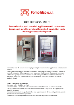
ISTRUZIONI D’USO UNITÀ CONDENSATRICI
(COMPRESSORI SEMIERMETICI E APERTI)
OPERATING INSTRUCTIONS CONDENSING UNITS
(SEMI-HERMETIC AND OPEN COMPRESSORS)
ИНСТРУКЦИЯ ПО ЭКСПЛУАТАЦИИ АГРЕГАТОВ (на базе
САЛЬНИКОВЫХ и БЕССАЛЬНИКОВЫХ компрессоров)
Istruzioni Operative / Operative Instructions / Instructions Operatives
SOMMARIO / SUMMARY / СОДЕРЖАНИЕ
Sicurezza / Safety / Правила техники безопасности
•
2
Descrizione generale / Overview / Краткий обзор
•
7
Installazione / Installaction / Установка агрегата
•
8
Collegamenti elettrici / Electrical connections / Электрические подключения
•
11
Messa in servizio / Commissioning / Ввод в эксплуатацию
•
12
Manutenzione / Maintenance / Техническое обслуживание
•
12
Emergenze / Emergency / Выход из строя
•
14
Dismissione / Dismantling / Демонтаж
•
14
Avvertenze / Warning / Предупреждение
•
15
Prospetto anomalie / Failures chart / Таблица возможных неисправностей
и их устранение
•
17
Figure / Figures / Рисунки
•
24
1
OFFICINE MARIO DORIN S.p.A.
Sicurezza
INFORMAZIONI
SUL
Safety
PRESENTE
DOCUMENTO
Si raccomanda di leggere
attentamente il contenuto di
queste istruzioni e conservarle
in
prossimità
dell’unità
condensatrice.
Le presenti istruzioni devono
essere utilizzate unitamente
alle istruzioni operative del
relativo compressore, che
saranno consegnate insieme
all’unità stessa. Nel caso non
siano presenti, si prega di
scaricarle da internet (dal sito
web www.dorin.com) o di
richiederle direttamente al
nostro Supporto Tecnico.
Si raccomanda inoltre di
mantenere una copia delle
presenti istruzioni e di quelle
del compressore presso gli
uffici
tecnici
dell’impresa
utilizzatrice.
Per qualsiasi intervento si
voglia effettuare sull’unità
condensatrice,
consultare
sempre
il
presente
documento,
attenendosi
strettamente alle indicazioni
in esso contenute; per tutto
ciò non espressamente citato,
prima
di
intervenire,
contattare
sempre
il
costruttore.
Il costruttore declina ogni
responsabilità
per
danni
causati a persone o cose
dovuti
alla
mancata
osservanza delle avvertenze
contenute in questo manuale.
Le Officine Mario Dorin S.p.A.
si riservano il diritto di
aggiornare
questa
pubblicazione in qualunque
momento
o
apportare
modifiche
a
componenti
dell’unità se questo viene
ritenuto
necessario
per
esigenze
costruttive
o
commerciali.
E’ vietata la riproduzione
INFORMATION ON THIS DOCUMENT
We recommend to read
carefully the content of these
instructions and to keep them
near the condensing unit.
These instructions have to be
applied together with the
operational instructions of the
corresponding
compressor
that will be delivered together
with the unit itself. Should they
not be available, you are
kindly asked to download
them from internet (from the
web site www.dorin.com) or
to ask them directly of our
Technical Division.
We also recommend to keep
a copy of these instructions
and
of
those
for
the
compressor at the technical
divisions
of
the
user
enterprise.
For any intervention you want
to
execute
on
the
condensing unit, look it up
always in this document,
strictly
following
the
indications it provides; for
anything
which
is
not
expressly mentioned, contact
always the manufacturer
before intervening.
The manufacturer refuses all
responsibility for the damages
caused to people or to things
because
of
the
nonconformity
with
the
instructions this handbook
provides.
Officine Mario Dorin S.p.A.
reserves the right to update
this publication at any time or
to change the components
of this unit if this is considered
as
necessary
for
manufacturing
or
commercial needs.
The
partial
or
total
reproduction
of
these
2
Правила техники
безопасности
ИНФОРМАЦИЯ ОБ ЭТОМ ДОКУМЕНТЕ
Мы рекомендуем тщательно
прочитать содержание этих
инструкций и хранить их
около
компрессорноконденсаторного
агрегата
(далее агрегат).
Эти
инструкции
должны
применяться
вместе
с
инструкциями
по
эксплуатации
поршневых
бессальниковых
или
сальниковых компрессоров,
в
зависимости
от
типа
компрессора, который будет
непосредственно
установлен в агрегат. Если
эти
инструкции
у
Вас
отсутствуют, то Вы можете
загрузить их из Интернета
(страница
веб
сайта
www.dorin.com ) или спросить
их у нашего технического
отдела.
Мы
также
рекомендуем
иметь копию этих инструкций
в
технических
отделах
холодильных компаний.
Прежде чем вмешаться в
работоспособность агрегата,
необходимо
изучить
соответствующий
раздел
настоящей инструкции; если
какая-либо
информация
отсутствует,
то
Вам
необходимо обратиться за
консультациями
в
технический отдел заводаизготовителя.
Завод-изготовитель
не
принимает на рекламацию
вышедших из строя изделий,
вызванных несоблюдением
персоналом
требований
настоящей инструкцией.
Officine Mario Dorin S.p.A
оставляет за собой право в
любое
время
модернизировать настоящую
инструкцию или
изменять
спецификацию
и
конструкцию изделия, если
Istruzioni Operative / Operative Instructions / Instructions Operatives
parziale o totale di queste
istruzioni senza l’autorizzazione
scritta delle Officine Mario
Dorin S.p.A.
Queste istruzioni non possono
contenere tutte le avvertenze
e precauzioni in grado di
coprire i rischi derivanti da
qualsiasi eventualità; deve
essere tenuto presente che
prudenza, attenzione, buon
senso, sono fattori che il
personale
che
effettua
l’installazione,
la
manutenzione e uso deve
possedere e sono elementi
che
il
costruttore
può
trasmettere
ma
non
aggiungere.
instructions
is
forbidden
without
the
written
authorization
by
Officine
Mario Dorin S.p.A.
These instructions cannot
include all the instructions
and the precautions able to
cover the risks resulting from
any event; you have to bear
in mind that caution, care
and common sense are
factors that the personnel,
who executes the installation
and the maintenance, has to
know; the manufacturer can
convey these elements but
cannot add them.
COMPLIANCE
WITH
THE
CONFORMITÀ NORMATIVA
REGULATIONS
L’unità condensatrice a cui si
riferisce questo manuale di
installazione / manutenzione
è classificata come “quasimacchina” ai sensi della
Direttiva
“Macchine”
2006/42/CE e NON deve
essere messa in servizio finché
la macchina finale in cui
deve essere incorporata non
è stata dichiarata conforme,
se del caso, alle disposizioni
della
stessa
Direttiva
“Macchine” 2006/42/CE.
I componenti elettrici sono
conformi alla Direttiva “Bassa
Tensione” 2006/95/CE.
I componenti in pressione
sono conformi alla Direttiva
“Apparecchi a pressione”
97/23/CE (art. 1 § 3.10).
Per
quanto
riguarda
il
compressore, fare riferimento
al relativo libretto di istruzioni
operative.
L’installatore
dell’unità
condensatrice
all’interno
dell’impianto
frigorifero
è
tenuto
a
rispettare
le
pertinenti disposizioni di legge
del paese di installazione in
riferimento
agli
impianti
elettrici ed agli impianti di
climatizzazione e le norme
della serie EN 378.
The condensing unit specified
and
described
in
this
installation / maintenance
manual
is
provided
for
incorporation in machines as
defined in the Machines
Directive 2006/42/EC; and
MUST NOT be put to use till
the final machine it has to be
incorporated to has not been
declared as compliant, if
need be, with the provisions
of
the
same
Directive
“Machines” 2006/42/EC.
The electronic components
are compliant with Directive
“Low Voltage” 2006/95/CE.
The
components
under
pressure are compliant with
the
Directive
“Pressure
devices” 97/23/EC (art. 1 §
3.10).
As far as the compressor is
concerned, you have to refer
to
the
corresponding
operational instruction book.
The
installer
of
the
condensing unit inside the
refrigerating
system,
is
obliged to follow the relevant
provisions of the law in the
installation country, making
reference to the electrical
systems and to the airconditioning systems, as well
as to the regulations of the EN
378 series.
3
это
потребуется
для
коммерческих
и
производственных целей.
Без письменного разрешения
Officine Mario Dorin S.p.A.
запрещается частичное или
полное изменение настоящих
инструкций.
Настоящие инструкции не
могут включать в себя все
рекомендации
и
меры
предосторожности,
способные
предотвратить
опасности, следующие из
любого случая; Вы должны
иметь в виду, что меры
предосторожности и здравый
смысл - факторы, которые
обслуживающий
и
эксплуатирующий установку
персонал должен знать.
СОБЛЮДЕНИЕ ИНСТРУКЦИЙ
Агрегат,
указанный
и
описанный в этой инструкции
по
эксплуатации
удовлетворяет
требованиям
Предписания
ЕС
по
машиностроению
2006/42/CE; и НЕ ДОЛЖЕН быть
использован
в
составе
агрегата,
компоненты
которого не удовлетворяют
условиям того же самого
Предписания
по
машиностроению
2006/42/EC.
Эл.
компоненты
агрегата
удовлетворяют требованиям
Предписания
ЕС
по
низковольтному
оборудованию 2006/95/CE.
Компоненты
агрегата,
работающие под давлением,
удовлетворяют требованиям
Предписания
ЕС
по
оборудованию,
работающего под давлением
97/23/CE (art. 1 § 3.10).
Поскольку компрессор входит в
состав агрегата, Вы должны
обратиться к соответствующей
инструкции по эксплуатации
компрессора.
Организация,
встраивающая
агрегат в холодильную систему,
обязана
соблюдать
все
национальные
и
местные
инструкции,
а
также
OFFICINE MARIO DORIN S.p.A.
PERSONALE QUALIFICATO
Qualsiasi
operazione
di
installazione
e/o
manutenzione di queste unità
dovrà essere eseguita solo da
personale qualificato ed in
accordo alle varie Normative
nazionali applicabili.
Questo manuale deve essere
letto attentamente prima di
eseguire ogni operazione sul
macchinario;
l’osservanza
delle
disposizioni
è
condizione necessaria per la
sicurezza dell’operatore e dei
macchinari interessati.
DISPOSITIVI
DI
PROTEZIONE
INDIVIDUALE
Per qualsiasi intervento di
trasporto,
installazione,
regolazione, manutenzione o
smantellamento dell’unità, il
tecnico addetto deve munirsi
di scarpe di sicurezza, guanti
di protezione ed occhiali di
protezione.
RISCHI RESIDUI
L’unità è stata progettata e
realizzata
cercando
di
eliminare
o
laddove
impossibile ridurre al minimo i
rischi per la sicurezza e la
salute degli utilizzatori.
Nonostante ciò, permangono
una serie di rischi residui per i
quali è indispensabile che
l’utilizzatore
adotti
delle
misure
di
sicurezza
complementari a quelle già
realizzate
tecnicamente
sull’unità.
PRESSIONE INTERNA
Prima di procedere alla
manutenzione
dell’unità,
rimuovere la pressione al suo
interno.
Non rimuovere parti dell’unità
soggette a pressione interna
prima di aver effettuato tale
operazione.
PRECARICA DELL’UNITÀ
All’interno dello stabilimento
di produzione l’unità è stata
opportunamente essiccata e
QUALIFIED STAFF
соответствие
электрических
Any
installation
and/or схем и систем воздушного
maintenance operation of кондиционирования
these units shall be carried предписаниям серии EN 378.
КВАЛИФИЦИРОВАННЫЙ ПЕРСОНАЛ
out by qualified staff only and
монтаж
и/или
according to the several Любой
мероприятия
по
обслуживанию
applicable
national
этих компрессоров должны
regulations.
выполнены
только
This manual shall be carefully быть
read before carrying out any квалифицированным
и
согласно
operation on the machinery; персоналом
the
observance
of
the применяемым национальным
provisions is essential to the инструкциям.
руководство
должно
operator as well as the Это
тщательно прочитано перед
involved machinery safety.
выполнением любого действия
с
холодильным
оборудованием; соблюдение
DEVICES FOR THE INDIVIDUAL SAFETY
For
any
transportation, этих условий относится как к
installation,
adjustment, обслуживающему персоналу
и
к
безопасности
maintenance or dismantling так
of the unit, the authorized эксплуатирующегося
technician has to supply оборудования.
СРЕДСТВА
ИНДИВИДУАЛЬНОЙ
himself with safety shoes,
ЗАЩИТЫ
protection
gloves
and
При
любых
работах
с
glasses.
оборудованием
(транспортировка, монтаж /
OTHER RISKS
демонтаж, обслуживание и
The unit was designed and
наладка)
обслуживающий
manufactured trying to avoid
персонал
должен
or, whenever it is not possible,
использовать
безопасными
to reduce to a minimum the
ботинками,
защитными
risks for the users’ safety and
перчатками и очками
ОСТАТОЧНАЯ ОПАСНОСТЬ
health.
Агрегат был разработан и
Nevertheless, there is still a
создан
с
учетом,
чтобы
series of other risks and for
избежать или уменьшать до
them
it
is
absolutely
минимума опасности для
necessary for the user to
обслуживающего персонала
implement
the
safety
и его здоровья.
measures complementary to
Однако, существует еще ряд
those technically already
других опасностей, и для них
applied to the unit.
необходимо осуществить ряд
INSIDE PRESSURE
дополнительных
мер
по
Before
starting
the
технике
безопасности
maintenance of the unit, take
обслуживающего персонала.
ВНУТРЕННЕЕ ДАВЛЕНИЕ
away the pressure inside.
Перед выполнением любых
Do not remove those parts of
сервисных
работ
по
the unit subject to an inside
обслуживанию
агрегата,
pressure
before
having
сбросьте
внутреннее
executed this operation.
давление, открывая заглушки
низкого и высокого давления.
PRE-CHARGE OF THE UNIT
Не
удалять
те
части
At the production factory, the
компрессора,
которые
unit has been appropriately
находятся под избыточным
dried and charged with
давлением прежде, чем не
4
Istruzioni Operative / Operative Instructions / Instructions Operatives
caricata con gas protettivo
(aria secca – PR-70) con
sovrappressione di circa 0,5 ÷
1 bar.
Prima
di
procedere
all’installazione
dell’unità,
scaricare la pressione di
precarica
agendo
sui
rubinetti. Non rimuovere alcun
componente dall’unità prima
di aver effettuato questa
operazione.
protective gas (dry air – PR70) with an extra pressure of
about 0,5 ÷ 1 bar
Before starting the installation
of the unit, discharge the
pressure of pre-charge by
acting on the service valves.
Do
not
remove
any
component from the unit
before having executed this
operation.
Attendere il raffreddamento /
riscaldamento delle superfici
esterne dopo lo spegnimento
del
compressore
per
intervenire sull’unità, in modo
che
non
siano
presenti
temperature pericolose.
Utilizzare guanti di protezione.
Installare l’unità in luoghi non
accessibili a personale non
informato sui rischi oppure
impedirne
l’accesso
con
recinzione.
BURNS FOR HEAT/FOR COLD
Wait for the cooling/heating
of the external surfaces after
the compressor stopped if
you want to intervene on the
unit; in this way there are not
dangerous temperatures on
the unit.
Make use of protection
gloves. Install the unit in
places
that
are
not
accessible to the staff who
does not know about the risks
or block their access by
means of fences.
IRRITAZIONI CUTANEE
SKIN IRRITATIONS
USTIONE DA CALDO / DA FREDDO
Attenzione: il compressore è
spedito con carica di olio.
Evitare il contatto diretto con
la pelle e con gli occhi, in
quanto irritante.
ASFISSIA
I refrigeranti HFC e HCFC non
sono tossici né nocivi, né
esplosivi, ma possono portare
ad asfissia nel caso di perdita
dell’impianto in ambiente non
correttamente aerato.
I refrigeranti HFC e HCFC sono
inodore e incolore e possono
non
essere
percepiti
direttamente in caso di
emissione.
Rispettare
le
prescrizioni
sull’aerazione dell’ambiente
di installazione.
RUMORE
Indossare
dispositivi
di
protezione dell’udito in caso
di permanenza prolungata in
prossimità
dell’unità
in
funzione.
Caution: the compressor is
shipped with a charge of oil.
Avoid the direct contact with
the skin and the eyes since it
is irritant.
ASPHYXIA
The
HFC
and
HCFC
refrigerants are not toxic or
injurious or explosive, but can
cause asphyxia in case of
system leak into a not
correctly well-aired place.
The
HFC
and
HCFC
refrigerants are odourless and
colourless and can be not
perceived directly in case of
emission.
Follow the instructions on
airing of the installation
place.
NOISE
Wear protection devices for
your hearing if you stay for a
long time near the working
unit.
5
выполнено это действие.
ПРЕДВАРИТЕЛЬНАЯ
ЗАПРАВКА
КОМПРЕССОРА
На
заводе,
агрегат
был
соответствующим
образом
высушен
и
заправлен
защитным
газом
(сухой
воздух – PR-70) с давлением
по
манометру
приблизительно 0,5÷1 бар.
Перед монтажом агрегата,
сбросьте
давление
предварительной
заправки
защитным газом, открывая
два
сервисных
запорных
вентиля.
Не
удалять
никаких
компонентов
компрессора
прежде, чем не выполнено
это действие.
ОЖОГИ ОТ ГОРЯЧЕЙ / ХОЛОДНОЙ
ПОВЕРХНОСТЕЙ
Если
требуется
провести
сервисные работы после
остановки
компрессора,
дождитесь пока горячие /
холодные
внешние
поверхности
компрессора
достигли
не
опасных
температур.
Использовать
защитные
перчатки. Установить агрегат
в
местах,
которые
не
доступны для персонала ,
который
не
знает
об
опасностях, блокировать их
доступ
посредством
установления
защитных
заграждений.
ПОВРЕЖДЕНИЯ КОЖИ
Предостережение:
компрессор
заправлен
холодильным
маслом.
Избегать прямого контакта
масла с кожей и с глазами,
так
как
оно
является
раздражителем.
АСФИКСИЯ
Гидрофторуглеродные HFC и
гидрохлорфторуглеродные
HCFC хладагенты не являются
ядовитыми, вредными или
взрывоопасными,
но
они
могут привести к нарушению
дыхания в случае утечки
хладагента из системы в
плохо
проветриваемое
помещение.
OFFICINE MARIO DORIN S.p.A.
LESIONI DOVUTE AL TRASPORTO E
INJURIES
MOVIMENTAZIONE
TRANSPORTATION AND HANDLING
Adottare le comuni misure di
sicurezza per il trasporto di
carichi
pesanti
mediante
attrezzature a forche o a
gancio.
Utilizzare unicamente il punto
di sollevamento indicato.
Indossare scarpe di sicurezza.
Take
the
usual
safety
measures
for
the
transportation of heavy loads
by means of forklift trucks or
hook equipments.
Use the indicated lifting point
only.
Wear safety shoes.
SEGNALETICA DI SICUREZZA
SAFETY INDICATIONS
Sul compressore sono riportati
i simboli grafici riportati sulle
relative istruzioni operative.
Sulle unità condensatrici sono
presenti:
The graphic signs indicated
on
the
corresponding
operational instructions are
reproduced
on
the
compressor.
On the condensing unit you
find:
PARTI IN ROTAZIONE
Le mani, i capelli e gli abiti
possono rimanere impigliati
nel
ventilatore
del
condensatore.
Prima
di
rimuovere
la
griglia
di
copertura fermare l’unità e
rimuovere
il
fusibile
di
protezione del motore.
Prestare
la
massima
attenzione! Pericolo di lesioni
gravi.
CORRENTE ELETTRICA
Esiste pericolo di folgorazione
qualora si venga a contatto
con i terminali elettrici. Il
coperchio
della
scatola
attacchi elettrici previene tale
contatto. Non alimentare
elettricamente il compressore
e i ventilatori (nel caso di
unità ad aria) fino a che il
coperchio della scatola non
sia completamente chiuso e
integro.
SUPERFICI CALDE/FREDDE
I componenti in pressione
possono avere temperature
tali da determinare ustioni da
caldo o da freddo. Prima di
lavorare sull’unità, fermarla e
aspettare la stabilizzazione
delle temperature.
CAUSED
BY
ROTATING PARTS
Hands, hair and garments
can get caught in the
condenser fan. Before taking
the covering grid away stop
the unit and remove the fuse
protecting the engine.
Pay the greatest attention!
Danger of serious injuries.
ELECTRICAL CURRENT
The danger of electrocution
exists when you are in
contact with the electrical
terminals. The lid of the box
for the electrical connections
prevent this contact. Do not
feed
electrically
the
compressor and the fans (in
case of air unit) till the lid of
the box is not completely
closed and integral.
HOT/COLD SURFACE
The temperatures of the
components under pressure
are such to cause burns for
heat or for cold. Before
working on the unit, stop it
and
wait
for
the
temperatures to be stable.
6
хладагенты
HFC
и
HCFC
бесцветные и без запаха
поэтому
их
утечку
нельзя
определить непосредственным
способом.
Следует
выполнять
рекомендации
инструкции
при проветривании места
установки компрессора.
ШУМ
При длительном пребывании
около работающего агрегата
следует
одевать
индивидуальные
средства
защиты от шума.
ПОВРЕЖДЕНИЯ, ВЫЗВАННЫЕ
ПРИ
ПОГРУЗКЕ И ТРАНСПОРТИРОВКЕ
При транспортировке тяжелых
грузов следует применять
стандартное оборудование,
такие как грузовые автокары
или подъемные краны.
Поднимать
только
за
обозначенные точки подъема
компрессора.
Носить безопасные ботинки.
ЗНАКИ БЕЗОПАСНОСТИ
Графические
знаки
безопасности,
обозначающие
соответствующие
эксплуатационные
инструкции, установлены на
компрессоре.
На агрегате Вы можете
найти:
ДВИЖУЩИЕСЯ ЧАСТИ
Руки, волосы и одежда могут
попасть во вращающийся
вентилятор
конденсатора.
Перед открытием кожуха,
отключить агрегат и удалить
защитный
плавкий
предохранитель.
Обратить самое большое
внимание!
Опасность
серьезных
повреждений.
ЭЛЕКТРИЧЕСКИЙ ТОК
Опасность
смерти
от
электрического
тока
существует всегда, когда Вы
находитесь в контакте с эл.
клеммами.
Крышка
клеммной
коробки
для
подключения компрессора к
Istruzioni Operative / Operative Instructions / Instructions Operatives
электросети предотвращает
этот контакт. Не подключать
компрессор
к
эл.
напряжению, пока крышка
клеммной
коробки
полностью не закрыта.
ГОРЯЧАЯ/ХОЛОДНАЯ
ПОВЕРХНОСТЬ
Температуры
компонентов
агрегата таковы, что они могут
причинить ожоги от горячей
или холодной поверхности.
Перед ремонтом агрегата,
остановить его и дождаться
пока
температура
поверхности
не достигнет
температуры
окружающей
среды.
Descrizione generale
Overview
Краткий обзор
Le unità condensatrici sono
dei seguenti tipi:
The
following
types
of
condensing
units
are
available:
Dorin
SpA
изготавливает
следующие типы агрегатов:
КОМП.
-КОНД.
АГРЕГАТЫ
UNITÀ CONDENSATRICI AD ARIA
Sono
costituite
da
un
basamento
in
lamiera
piegata su cui sono montati il
compressore (semiermetico o
aperto), il condensatore con i
ventilatori, il ricevitore di
liquido (dotato di valvola di
sicurezza). Sono previste di
serie
le
tubazioni
di
collegamento
fra
compressore e condensatore
e
fra
condensatore
e
ricevitore.
ВОЗДУШНОГО ОХЛАЖДЕНИЯ
They consists of a base made
of bent plate where the
compressor (semi-hermetic or
open), the condenser with
the fans, the liquid receiver
(equipped with a safety
valve) are installed.
Standard connection pipes
are provided between the
compressor
and
the
condenser and between the
condenser and the receiver.
В состав агрегата входят:
монтажная
рама,
компрессор
(бессальниковый
или
сальниковый), конденсатор с
вентиляторами,
жидкостной
ресивер
(оборудованный
предохранительным
клапаном).
Стандартный
трубопровод
соединяет компрессор
и
конденсатор, конденсатор и
ресивер.
КОМП. –КОНД. АГРЕГАТЫ ВОДЯНОГО
AIR CONDENSING UNITS
UNITÀ CONDENSATRICI AD ACQUA
WATER CONDENSING UNITS
ОХЛАЖДЕНИЯ
Sono
costituite
da
un
condensatore
a
fascio
tubiero
orizzontale,
con
piastra di supporto, su cui è
montato
il
compressore
semiermetico. È prevista di
serie
la
tubazione
di
collegamento
fra
compressore e condensatore.
Il condensatore è dotato di
valvola di sicurezza.
They consists of a condenser
with a horizontal tube nest,
with a supporting plate,
where
the
semi-hermetic
compressor is installed.
Standard connection pipes
are provided between the
compressor
and
the
condenser. The condenser is
equipped with safety valves.
UNITÀ REMOTE
REMOTE UNITS
Sono
costituite
da
un
ricevitore
di
liquido
orizzontale, con piastra di
They consists of a horizontal
liquid
receiver
with
a
supporting plate where the
Агрегаты включают в себя
водяной
конденсатор
с
горизонтально
расположенными трубками
теплообмена,
монтажную
раму,
на
которую
устанавливается бессальниковый компрессор.
Стандартный
трубопровод
соединяет компрессор
и
водяной
конденсатор.
Конденсатор
оборудован
предохранительным
клапаном.
ОТДЕЛЬНОСТОЯЩИЕ АГРЕГАТЫ
Они
состоят
из
7
OFFICINE MARIO DORIN S.p.A.
supporto, su cui è montato il
compressore semiermetico. Il
ricevitore è dotato di valvola
di sicurezza.
semi-hermetic compressor is
installed. The receiver is
equipped with a safety valve.
USO PREVISTO DELL’UNITÀ
EXPECTED USE OF THE UNIT
L’unità è stata progettata e
costruita unicamente per la
compressione di refrigeranti
HFC (R404A / R507 / R134a /
R407C) e HCFC - CFC (solo
dove
permesso
dalle
legislazioni
nazionali)
nei
campi operativi riportati nelle
istruzioni operative del relativo
compressore.
This unit has been designed
and manufactured only for
the compression of the HFC
(R404A / R507 / R134a /
R407C) and HCFC – CFC
refrigerants (wherever the
national laws allow it, only) in
the
operational
fields
indicated in the operational
instructions
of
the
corresponding compressor.
IDENTIFICAZIONE DELL’UNITÀ
UNIT IDENTIFICATION
Ogni unità è identificata
attraverso il numero di serie
riportato
sulla
targhetta
metallica
rivettata
sul
compressore.
Sulle unità ad aria è riportata
una
ulteriore
targhetta
adesiva in cui sono riportati i
seguenti dati:
Each unit is identified thanks
to
a
serial
number
reproduced on the metal
plate
riveted
on
the
compressor.
On the air units, an additional
adhesive plate is reproduced
Showing the following data:
•
•
•
•
•
•
•
•
•
Nome del costruttore
Modello dell’unità
Numero di serie
Anno di fabbricazione
Pressione di progetto
Temperatura di progetto
Refrigeranti utilizzabili
Anno di produzione
Categoria
•
•
•
•
•
•
•
•
•
Manufacturer’s name
Unit model
Serial number
Manufacture year
Design pressure
Design temperature
Usable refrigerants
Production year
Category
Nelle comunicazioni con le
O.M.D. è importante fare
riferimento al numero di
matricola del compressore al
fine di consentire una corretta
e veloce rintracciabilità del
prodotto.
For communications with
O.M.D. it is important to make
reference to the registration
number of the compressor in
order to allow a correct and
quick traceability of the item.
Installazione
Installation
! ATTENZIONE:
Qualora
l’imballo
risulti
! ATTENTION:
Should
packaging
8
горизонтального жидкостного
ресивера
с
монтажной
пластиной,
на
которой
установлен бессальниковый
компрессор.
Жидкостной
ресивер
оборудован
предохранительным
клапаном.
ОБЛАСТЬ ПРИМЕНЕНИЯ АГРЕГАТА
Этот агрегат был разработан
и
изготовлен
только
для
работы с HFC (R404A / R507 /
R134a / R407C) и HCFC – CFC
хладагентами
(если
разрешено применение на
основании
национальных/местных
законов)
в
области
эксплуатации, указанные в
инструкциях по эксплуатации
соответствующих
компрессоров.
ИДЕНТИФИКАЦИЯ АГРЕГАТА
Каждый
идентифицирован
благодаря
серийному
номеру,
указанному
на
металлической
заводской
пластине, прикрепленной к
компрессору.
На
агрегатах
воздушного
охлаждения
прикреплена
дополнительная пластина, на
которой
указываются
следующие данные:
• Наименование
производителя
• Модель агрегата
• Серийный номер
• Дата изготовления
• Расчетное давление
• Расчетная температура
• Применяемый хладагент
• Номинальное
напряжение, В
• Категория
Для общения с O.M.D. очень
важно сделать
ссылку на
регистрационный
номер
компрессора.
Это
необходимо, чтобы быстро и
корректно
отслеживать
изделие.
Установка агрегата
be
! ВНИМАНИЕ:
Если упаковка повреждена,
Istruzioni Operative / Operative Instructions / Instructions Operatives
danneggiato e/o sussistano
comunque
dubbi
sulla
integrità dell’unità ricevuta
non
procedere
all’installazione dello stessa.
damaged and/or doubts on
the
integrity
of
the
compressor received arise do
not
proceed
to
the
compressor installation.
и/или имеются сомнения по
целостности
полученного
компрессора,
компрессор
не устанавливать.
TRASPORTO DELL’UNITÀ
UNIT TRANSPORT
Nel caso l’unità sia priva di
pallet, la movimentazione
deve avvenire come indicato
in
figura
1,
verificando
preventivamente la portata
del gancio di sollevamento
dell’attrezzatura usata rispetto
al peso indicato in figura 2.
Should the unit be without
pallet, the handling has to be
executed as it is indicated in
figure 1, by checking in
advance the capacity of the
lifting hook of the employed
equipment compared with
the weight indicated in figure
2.
POSIZIONAMENTO
ASSEMBLY
L’unità può essere posizionata
in un locale opportunamente
areato oppure all’esterno
purché ben riparata dalle
intemperie. In entrambi i casi
la macchina deve essere
accessibile solo al personale
autorizzato.
It is possible to place the unit
into a suitably well-aired room
or outdoor provided that it is
well sheltered from bad
weather. In both cases the
machine
has
to
be
accessible to the authorized
staff only.
Installare
l’unità
orizzontalmente; nel caso di
unità condensatrice ad aria,
mantenere sufficiente spazio
vuoto dietro al condensatore
per consentire il corretto flusso
d’aria.
Install the unit horizontally;
should
it
be
an
air
condensing
unit,
keep
enough empty space behind
the condenser in order to
allow the suitable air flow.
Осуществлять перемещение
упакованного агрегата на
поддонах.
При
этом
использовать
соответствующие
средства
для подъема веса агрегата
(грузовой
автокар),
обозначенного на Рис. 2.
Если агрегат без поддона, то
при
подъеме
применять
только подъемный кронштейн
(рым-болт) как указано на
Рис.1. Подъемное устройство
должно
соответствовать
подъему
веса
агрегата,
обозначенного на Рис. 2.
УСТАНОВКА АГРЕГАТА
Агрегат
необходимо
установить
в
хорошо
проветриваемом
помещении,
если
он
установлен «на улице», то его
необходимо
защитить
от
непогоды. В обоих случаях
агрегат должен быть доступен
только для обслуживающего
персонала.
Установить
агрегат
в
горизонтальном положении;
если это агрегат воздушного
охлаждения,
то
его
необходимо
установить
таким образом, чтобы после
конденсатора
было
свободное пространство для
создания свободного потока
воздуха.
AERAZIONE LOCALE INSTALLAZIONE
AIRING OF THE INSTALLATION ROOM
ВЕНТИЛЯЦИЯ МАШИННОГО ОТДЕЛЕНИЯ
Per evitare concentrazioni
pericolose di refrigerante in
caso
di
fuoriuscita
accidentale, è necessario
disporre
di
adeguata
ventilazione
nel
locale
tecnico
dove
viene
posizionata l’unità. Il locale di
installazione
deve
essere
provvisto
di
aerazione
naturale
o
ventilazione
meccanica, in accordo alle
norme tecniche applicabili.
To
avoid
dangerous
concentrations of refrigerant
in case of casual leak, it is
necessary to provide a
suitable airing in the technical
room where the unit is
located. The installation room
has to be equipped with
natural airing or mechanical
ventilation, in compliance
with the applicable technical
regulations.
Чтобы
избежать
любых
опасных
концентраций
хладагента при случайной его
утечки, необходимо иметь
надлежащую вентиляцию в
машинном отделение, где
установлена
холодильная
установка.
Машинное
отделение
должно
быть
оборудовано
естественной
или
механической
вентиляцией
согласно
применяемым техническим
инструкциям.
ТРАНСПОРТИРОВКА АГРЕГАТА
Il
trasporto
dell’unità
imballata su pallet deve
avvenire sollevandolo tramite
un carrello elevatore a
forche,
verificando
preventivamente la portata
dello stesso rispetto al peso
indicato in figura 2.
The
transport
of
the
packaged unit on pallets has
to be executed by lifting it by
means of a forklift truck, by
checking in advance its
capacity compared with the
weight indicated in figure 2.
9
OFFICINE MARIO DORIN S.p.A.
Dal momento che eventuali
fughe
di
refrigerante
tenderebbero a occupare la
parte inferiore dell’ambiente
circostante si raccomanda di
porre l’aspirazione del sistema
di ricambio aria in posizione
ribassata.
Since
possible
refrigerant
leaks would tend to occupy
the lowest part of the
surrounding
space
we
recommend to place the
suction of the air exchange
system in a lower position.
Поскольку возможны утечки
хладагента,
рекомендуется
систему
вытяжки
воздуха
(системы
вентиляции)
размещать в более низком
положении (ближе к полу
помещения).
COLLEGAMENTO DELLE TUBAZIONI
PIPES CONNECTIONS
СОЕДИНЕНИЕ ТРУБОПРОВОДА
Prima
di
procedere
all’installazione
dell’unità,
scaricare la pressione di
precarica
agendo
sui
rubinetti. Non rimuovere alcun
componente prima di aver
effettuato questa operazione.
Before starting the installation
of the unit, discharge the
pressure of pre-charge by
acting on the service valves.
Do
not
remove
any
component before having
executed this operation.
Перед
началом
монтажа
агрегата сбросить давление
защитного газа. Не снимать
присоединительные
элементы до полного сброса
избыточного давления.
Procedere
all’installazione
come segue:
- Rimuovere i rubinetti da
saldare;
- Saldare i rubinetti alle
tubazioni dell’impianto;
- Rimontare i rubinetti;
- Eseguire la verifica delle
perdite
dalle
tubazioni
mediante prova in pressione
con N2 o aria secca,
seguendo tutte le procedure
di sicurezza necessarie, come
ad esempio l’impiego di un
riduttore
di
pressione
interposto tra la bombola e
l’impianto e lasciando i
rubinetti chiusi (ATTENZIONE!
Durante questa prova non
superare la pressione di
standstill);
- Aprire i rubinetti;
- Rimuovere
l’aria
dall’impianto mediante vuoto
fino a minimo 1,5 mbar;
- Procedere alla carica del
refrigerante nell’impianto.
Execute the installation in the
following way:
- Remove the service valves
to be welded;
- Weld the service valves to
the system pipes;
- Reassemble the service
valves;
- Check the leaks from the
pipes by means of a
pressure test with N2 or dry
air following all the required
safety procedures such as,
for example, the use of a
pressure reducer placed
between the bottle and the
system and leaving the
service valves
closed
(ATTENTION! During this test
do
not
overcome
the
standstill pressure);
- Open the service valves;
- Take away the air of the
system by means of the
vacuum till a minimum of 1,5
mbar;
- Fill up the system with
refrigerant.
! Attenzione:
Non usare il compressore per
fare il vuoto.
Non
alimentare
elettricamente il compressore
in condizioni di vuoto!
! Attention:
Do not use the compressor to
create a vacuum.
Do not feed electrically the
compressor
in
vacuum
conditions!
! Attenzione:
Non utilizzare il compressore
per
fare
la
carica
di
refrigerante nell’impianto.
! Attention:
Do not use the compressor to
fill up the system with
refrigerant.
10
Монтаж
агрегата
осуществить
следующим
способом:
- Снять запорные вентили;
- Припаять запорные вентили
к трубопроводу;
Повторно
установить
запорные вентили;
- Проверить герметичность
системы с использованием
азота
(N2)
или
сухого
воздуха
с
соблюдением
всех норм и правил по
безопасности. (ВНИМАНИЕ!
Во время проведения этого
испытания не превышать
разрешенного давления);
- Открыть запорные вентиля;
- Удалить воздух из системы
посредством
вакуумного
насоса
до
достижения
вакуума минимум в 1,5
мбар;
Заправить
систему
хладагентом.
! Внимание:
Не
использовать
компрессор, как вакуумный
насос.
Не включать компрессор в
условиях вакуума!
! Внимание:
Не использовать компрессор
для заправки хладагента в
систему.
! Внимание:
Перед
запорных
соединением
вентилей
с
Istruzioni Operative / Operative Instructions / Instructions Operatives
! ATTENZIONE:
Prima di collegare i rubinetti
alle tubazioni assicurarsi che
tutti i tappi in plastica siano
stati rimossi.
Evitare per quanto possibile
l’ingresso di aria nell’unità!
Tenere chiuse le connessioni
durante la saldatura dei
rubinetti alle tubazioni.
Mantenere chiusi i rubinetti,
una volta rimontati, finché
non si avvia la procedura di
messa in vuoto.
Assicurarsi
che
tutte
le
tubazioni e le giunzioni siano
perfettamente pulite e a
tenuta.
Le indicazioni relative alle
connessioni standard sono
presenti nella figura 2.
трубопроводом,
удостоверьтесь,
что
все
пластмассовые
колпачки
были сняты.
По возможности
избегать
попадания воздуха в агрегат!
Во время пайки вентилей к
трубопроводу, его концы
должны быть герметично
закрыты.
После установки запорных
вентилей, они должны быть
закрыты до тех пор, пока не
будет проведено испытание
системы на герметичность.
Перед
соединением
указанных
вентилей
с
трубопроводом,
удостоверьтесь,
что
все
компоненты и трубопровод
совершенно
чистые
и
The indications regarding
закреплены.
standard connections are
Стандартные
соединения
shown in figure 2.
показаны на Рис. 2.
! Attention:
Before
connecting
said
valves to pipes make sure all
plastic caps have been
removed
Avoid, as much as possible,
the air inlet into the unit!
Keep the connections closed
during the welding of the
service valves to the pipes.
Once the service valves have
been reassembled, keep
them closed till the vacuum
procedure
is
not
implemented.
Be sure that all the pipes and
the joints are perfectly clean
and tight.
Collegamenti
elettrici
Electrical
connections
Электрические
подключения
Per il collegamento elettrico
del compressore, riferirsi alle
relative istruzioni operative o
vedere anche la pagina web
www.dorin.com.
For the electrical connection
of the compressor make
reference
to
the
corresponding
operational
instructions or see also the
web page www.dorin.com
Перед
подключением
компрессора к электросети
изучить
соответствующие
инструкции по эксплуатации
или
посмотреть страницу
веб сайта www.dorin.com.
Connect
electrically
the
electric equipments wherever
they are available and the
fans if it is the case of air
condensing unit (see the
indications showed inside the
electrical box). The plate on
each fan indicates the
voltage
and
frequency
values of the engine: be sure
that they are compliant with
the
voltage
and
the
frequency of the line.
Подключить к эл. сети, где это
необходимо, электрическое
оборудование,
а
также
вентиляторы, если это агрегат
воздушного охлаждения (см.,
схему подключения, которая
находится
в
клеммной
коробке).
На
каждом
вентиляторе
установлена
заводская
пластина,
на
которой
указано
эл.
напряжение и частота эл.
тока: убедитесь, что они
соответствуют
местной
электросети.
! Внимание:
Возможна
опасность
короткого замыкания из-за
присутствия конденсата в
клеммной
коробке
подключений к электросети.
Collegare elettricamente le
apparecchiature elettriche,
laddove
previste,
e
i
ventilatori nel caso di unità
condensatrici ad aria (vedere
le
indicazioni
riportate
all’interno
della
scatola
elettrica). La targhetta posta
su ogni ventilatore riporta i
valori di tensione e frequenza
del motore: assicurarsi che
siano in accordo con la
tensione e frequenza della
linea.
! Attenzione:
Pericolo
di
cortocircuito
dovuto alla presenza di
condensa
nella
scatola
attacchi elettrici.
Usare
esclusivamente
passacavi
standard
e
! Attention:
Danger of short circuit due to
the presence of condensate
in the electrical connections
box.
Exclusively
use
standard
fairleads and be careful while
11
OFFICINE MARIO DORIN S.p.A.
prestare
la
massima
attenzione nell’effettuare una
ermetizzazione
corretta
durante il montaggio.
carrying out the correct
airtight sealing during the
assembly.
Использовать исключительно
стандартные
уплотнительные порты для
ввода кабелей в клеммную
коробку.
Messa in servizio
Commissioning
Ввод в эксплуатацию
Prima di mettere in marcia
l’unità, vedere le istruzioni
operative
del
relativo
compressore.
Before starting the unit, read
the operational instructions of
the
corresponding
compressor.
Prima di mettere in marcia
un’unità condensatrice ad
aria, verificare inoltre che:
9 Il rubinetto di partenza
liquido sia aperto;
9 I
ventilatori
siano
funzionanti.
9 Il pressostato di alta sia
installato, che non sia
isolabile
durante
il
funzionamento, che il
valore di taratura sia
inferiore a quello della
valvola di sicurezza e che
il relativo collegamento
elettrico
fermi
il
compressore qualora la
pressione di mandata
superi il valore di set.
Before
starting
the
air
condensing unit also check
what follows:
9 The start up liquid service
valves is open;
9 Fans are running;
9 The high manostat is
installed, that it is not
possible to isolate it
during the functioning,
that
the
calibration
value is lower than the
one of the safety valve
and
that
the
corresponding
electric
connection stops the
compressor
if
the
delivery pressure is higher
than the set value.
Перед
пуском
агрегата,
прочитать
инструкции
по
эксплуатации
соответствующего
компрессора.
Перед
пуском
агрегата
воздушного
охлаждения
необходимо проверить:
9 Запорные вентили на
жидкостной
линии
открыты;
9 Вентиляторы воздушного
конденсатора
вращаются;
9
Манометр
высокого
давления
в
рабочем
состоянии, откалиброван по
давлению
ниже,
чем
давление
одного
из
предохранительных клапанов,
при превышении давлении
нагнетания,
компрессор
останавливается.
Verificare che gli eventuali
altri accessori (pressostati,
regolatore velocità ventole,
elettrovalvola
solenoide)
siano installati e funzionanti
correttamente.
Check that possible other
accessories (manostats, fan
speed
controls,
solenoid
electric valve) are installed
and work correctly.
Manutenzione
Maintenance
PROCEDURA
DELL’UNITÀ
DI
ISOLAMENTO
Prima di intervenire sull’unità
per attività di manutenzione è
necessario sezionare la stessa
dall’alimentazione elettrica.
Installare
sulla
linea
di
alimentazione elettrica un
sezionatore
lucchettabile;
portarlo in posizione aperta
(0) e lucchettarlo durante
l’intervento di manutenzione.
PROCEDURE
FOR
THE
Проверить,
что
другие
принадлежности
(манометры,
уст-во
регулировки
скорости
вращения
вентилятора,
соленоидный
вентиль)
установлены
и
работоспособны.
Техническое
обслуживание
UNIT
ПРОЦЕДУРА
ОБСЛУЖИВАНИЯ
INSULATION
АГРЕГАТА
Before carrying out any kind
of intervention on the unit it is
necessary to interrupt the
main power supply of the
system.
Install on the power supply
line a switch selector that can
be padlocked, place it in an
open condition (0) and
padlock
it
during
the
Перед выполнением любого
вида
технического
обслуживания
машины
необходимо
отключить
главное
электропитание
системы.
Установить
на
линию
электропитания
переключатель - коммутатор,
который
может
отключать
12
Istruzioni Operative / Operative Instructions / Instructions Operatives
A seguito dell’installazione,
nel caso di interventi che
richiedono lo smontaggio di
parti dell’unità o per il suo
smantellamento, è necessario
procedere
alla
depressurizzazione secondo le
seguenti indicazioni:
• Sezionare l’alimentazione
elettrica
come
sopra
indicato;
• Chiudere la valvola di
intercettazione
posta
sull’aspirazione
del
compressore;
• Chiudere la valvola di
intercettazione posta sulla
linea di mandata, a valle
della zona di intervento;
• Depressurizzare il tratto
della linea di interesse (senza
disperdere
il
refrigerante
nell’ambiente) fino a che la
pressione non è diventata
quella atmosferica.
maintenance.
After the installation, in case
of interventions requiring the
dismantling of parts of the
unit or for its dismantling, it is
necessary
to
start
the
depressurization according to
the following indications:
• Dissect
the
electric
feeding as it is above
specified;
• Close the on-off valve
placed on the suction of the
compressor;
• Close the on-off valve
placed on the delivery line,
downstream
of
the
intervention area;
• Depressurize the involved
section of the line (without
dispersing the refrigerant in
the room) till the pressure
does not correspond to the
atmospheric one.
Se
si
rende
necessario
lavorare con la scatola
attacchi elettrici aperta e
sotto tensione, l’operazione
deve essere eseguita da
personale specificatamente
qualificato per operare su
impianti elettrici in tensione.
In nessun caso insistere con il
riarmo
della
protezione
elettrica
dopo
un
cortocircuito.
Prima
di
rimettere
in
funzione
l’impianto il guasto deve
essere eliminato e devono
essere sostituiti tutti quei
componenti che possono
essere danneggiati.
In case it is necessary to work
with the live open electric
board, such operation shall
be carried out by qualified
and expert staff.
In
no
case
keep
on
reactivating
the
electric
protection after a short
circuit.
Before
re-operating
the
system, the failure shall be
eliminated and all damaged
components
shall
be
replaced.
CONTROLLO AD INTERVALLI REGOLARI
CONTROL AT REGULAR INTERVALS
¾
Verificare
il
livello
dell’olio;
¾
Prelevare un campione
di olio per verificarne la
buona qualità (colore e
acidità).
¾
Ad
ogni
sostituzione
dell’olio verificare il filtro
dell’olio.
¾
Verificare il grado di
umidità nel refrigerante.
¾
Verificare
il
corretto
¾
Verify oil level;
¾
Take a sample of oil and
verify its good quality (color
and acidity).
¾
Every time the oil is
replaced, the oil filter shall be
verified.
¾
Verify
degree
of
moisture in refrigerant.
¾
Check
the
correct
working of the safety valve at
the set value. Checks have to
питание
во
время
обслуживания изделия.
При
ремонте
отдельных
частей агрегата или при
полном
его
демонтаже
следует сбросить давление в
компрессоре,
придерживаясь следующей
последовательности:
•
Отключить
электропитание, как было
упомянуто выше;
•
Закрыть всасывающий
запорный вентиль;
•
Закрыть нагнетательный
запорный вентиль;
•
Сбросить
давление
агрегата (не
сбрасывать
хладагент в окружающее
помещение), пока давление
не
будет соответствовать
атмосферному.
Любая
работа
с
электрическим
оборудованием должна быть
выполнена
квалифицированным
и
опытным персоналом.
Ни в каком случае не
восстанавливать
электрическую защиту после
короткого замыкания.
Перед последующим пуском
установки,
все
неисправности
и
поврежденные
компоненты
должны быть заменены.
РЕГУЛЯРНАЯ
ПРОВЕРКА
РАБОЧИХ
ДАННЫХ
13
¾
Проверить
уровень
масла;
¾
Взять образец масла и
проверить его качество (цвет
и кислотность);
¾
Каждый
раз,
когда
происходит замена масла,
масляный
фильтр
также
должен быть заменен.
¾
Проверить
степень
влажности хладагента.
¾
Проверить
работоспособность
предохранительного клапана.
OFFICINE MARIO DORIN S.p.A.
funzionamento della valvola
di sicurezza al valore di set. I
controlli
vanno
effettuati
periodicamente in accordo
alle
prescrizioni
delle
normative vigenti nel paese di
installazione.
¾
Verificare l’intasamento
del condensatore (per unità
condensatrici ad aria).
¾
Per unità condensatrici
ad aria, verificare il corretto
funzionamento
del
pressostato di alta pressione. I
controlli
vanno
effettuati
periodicamente in accordo
alle
prescrizioni
delle
normative vigenti nel paese di
installazione.
be carried out on a regular
basis following the provisions
of the regulations into force in
the installation country.
¾
Verify clogging of the
condenser
(for
aircondensing units).
¾
For air condensing units,
check the correct working of
the high pressure manostat.
Checks have been carried
out on a regular basis
following the provisions of the
regulations into force in the
installation country.
Emergenze
Emergency
Выход из строя
Nel
caso
di
malfunzionamento chiamare
il più vicino centro di
assistenza.
In caso di fuga di gas
refrigerante aerare il locale
dove è avvenuta la fuga
prima di intervenire. Non
sostare
nel
locale
di
installazione se non è stato
opportunamente
areato;
anche se il gas inalato non è
nocivo, questo sostituisce
l’ossigeno e quindi può dare
origine
a
sintomi
di
soffocamento.
In caso di incendio spegnere
la
macchina
agendo
sull’interruttore generale a
monte dell’apparecchiatura.
Non
usare
acqua
per
spegnere le fiamme ma solo
estintori a secco.
In case of malfunctioning or
black-out call the nearest
service centre.
В случае поломки или аварии
установки
вызвать
специалистов из ближайшего
Сервис Центра.
В случае утечки хладагента,
перед любым мероприятием
по
устранению
неисправности
проветрить
помещение, где эта утечка
произошла. Не оставаться в
оно
помещении,
если
должным
образом
не
проветрилось; даже если газ,
который вдыхается не вреден,
газ вытесняет кислород и
поэтому может привести к
удушью.
В случае пожара выключить
установку
главным
выключателем.
Dismissione
Dismantling
Демонтаж
! Attenzione:
L’unità può essere sotto
pressione!
Pericolo di gravi ustioni
Usare guanti e occhiali
protettivi.
! Attention:
The unit can be under
pressure!
Danger of serious burns.
Wear protective gloves and
glasses.
! Внимание:
Агрегат может находиться
под давлением. Опасность
серьезных
ожогов.
При
выполнении работ носить
защитные перчатки и очки.
In case of refrigerant gas
leak, aerate the room where
the leak occurred before any
operations. Do not stay in the
machinery room if it has not
been properly aerated; even
if the gas inhaled is not
harmful, the gas replaces
oxygen and can therefore
cause choking symptoms.
In case of fire turn off the
machine by the general
switch upstream.
Do not use water to extinguish
the flames but only use dry
extinguishers.
14
Его калибровка должна быть
проведена в соответствии с
требованиями
страны, где
устанавливается агрегат.
¾
Проверить
чистоту
поверхности
конденсатора
(для комп. – конд. агрегатов
воздушного охлаждения).
¾
Для
агрегатов
воздушного
охлаждения
проверить
работоспособность
манометра
высокого
давления.
Его калибровка должна быть
проведена в соответствии с
требованиями
страны, где
устанавливается агрегат.
При тушении пожара не
использовать
воду.
Применять
только
сухие
огнетушители.
Istruzioni Operative / Operative Instructions / Instructions Operatives
Quando verrà deciso di non
utilizzare più l’impianto, si
raccomanda
di
renderlo
inoperante
eliminando
opportunamente i materiali.
In conformità alle norme per
lo smaltimento vigenti nei vari
paesi e per il rispetto
dell’ambiente
le
parti
dell’impianto devono essere
divise per tipologia di rifiuto in
modo da poter smaltire o
recuperare opportunamente.
SMONTAGGIO DELL’UNITÀ
• attuare la procedura di
isolamento
descritta
al
capitolo Manutenzione;
• chiudere
i
rubinetti
sull’unità;
• aspirare il refrigerante;
• rimuovere le viti di fissaggio
dei rubinetti;
• smontare i supporti di
fissaggio dell’unità a terra;
• rimuovere l’unità come
indicato al capitolo Trasporto
e posizionamento.
! Attenzione:
Non disperdere il lubrificante
nell’ambiente; è un rifiuto
speciale e come tale deve
essere smaltito secondo le
norme in vigore.
When the system is no longer
used, it shall be made
inoperative
by
properly
eliminating materials.
In compliance with the
standards in force in the
different countries regarding
the waste disposal and the
respect of the environment,
the parts of the system shall
be divided according to the
waste types so as to dispose
of and recycle materials in a
proper way.
UNIT DISASSEMBLY
• implement the insulation
procedure described in the
Maintenance section;
• close the service valves on
the unit;
• suck the refrigerant;
• remove
the
screws
fastening the valves;
• remove
the
mounting
points of the unit on the
ground;
• remove
the
unit
as
described
in
chapter
Transportation
and
positioning.
! Attention:
Do not waste the lube in the
environment: it is special
waste and as such it shall be
disposed of according to the
standards in force.
Если установка больше не
эксплуатируется,
то
она
должна
быть
должным
образом
выведена
из
холодильной
системы
с
последующей
утилизацией
компонентов и материалов.
В соответствии с правилами
защиты окружающей среды,
части установки должны быть
разделены по типам, для
последующей переработки
надлежащим способом.
РАЗБОРКА АГРЕГАТА
• снять тепловую изоляцию
согласно
процедуре,
описанной
в
разделе
«Обслуживание»;
●
закрыть
на
агрегате
сервисные вентили;
●
откачать
находящийся
внутри агрегата хладагент;
●
удалить винты крепления
вентилей на компрессоре;
●
удалить точки крепления
агрегата
на
монтажной
раме;
•
снять агрегат с рамы,
как
описано
в
разделе
«Транспортировка и установка
компрессора».
! Внимание:
Не сливать отработанное
машинное
масло
в
окружающую
среду:
это
специальные отходы и их
следует
утилизировать
с
соблюдением правил защиты
окружающей среды.
Avvertenze
Warning
Предупреждение
Qualsiasi
operazione
di
smontaggio
o
modifica
dell’unità può pregiudicare la
iniziale
conformità
del
prodotto
alle
norme
e
direttive applicabili.
Any disassembly action or
modification made on any
DORIN product can affect
product compliance to the
aforesaid directives.
Любые
мероприятия
по
разборке или модификации
любого изделия компании
DORIN,
должны
соответствовать
вышеупомянутым
предписаниям ЕС.
OFFICINE MARIO DORIN S.p.A.
всегда не будет признавать
гарантию
на
изделия
ссылаясь
на
вышеупомянутые
предписания
ЕС,
если
изделия не модернизированы
или
не
созданы
OFFICINE MARIO DORIN S.p.A.
non riconosce/garantisce la
conformità dei propri prodotti
alle attuali norme e direttive
cogenti qualora vengano
revisionati da soggetti diversi
dal costruttore.
Di conseguenza si informa
DORIN
will
not
recognize/guarantee product
conformity to the aforesaid
directives
whenever
the
products are NOT overhauled
from DORIN itself.
Consequently we inform you
that, if necessary, the unit
15
OFFICINE MARIO DORIN S.p.A.
che,
qualora
necessario,
l’unità
dovrà
essere
manutenuta
e
riparata
esclusivamente da OFFICINE
MARIO DORIN S.p.A.
Dunque
OFFICINE
MARIO
DORIN S.p.A. declina ogni tipo
di responsabilità qualora si
verificassero danni a persone
o cose derivanti da qualsiasi
malfunzionamento di ogni
proprio
prodotto
qualora
venga revisionato da soggetti
diversi dal costruttore.
must
be
serviced
and
repaired only by OFFICINE
MARIO DORIN S.p.A.
Therefore DORIN declines any
type of responsibility in case
damages of any nature
occurs to things or persons
due
to
product
malfunctioning in case the
product have not been
overhauled from DORIN itself.
16
непосредственно компанией
OFFICINE MARIO DORIN S.p.A.
Компания
DORIN
всем
сообщает, что компрессор
должен
обслуживаться
и
ремонтироваться
только
OFFICINE MARIO DORIN S.p. A.
Поэтому DORIN снимает с
себя
любую
ответственность,
если
оборудование работает со
сбоями
после
восстановления,
которое
проведено
не
непосредственно компанией
DORIN, вследствие чего могут
возникнуть убытки любого
характера относящиеся к
вещам или к людям из-за
плохой работы изделия.
Istruzioni Operative / Operative Instructions / Instructions Operatives
Prospetto sinottico degli
inconvenienti e delle
possibili cause
ANOMALIA
FAILURE
НЕИСПРАВНОСТЬ
1
Il compressore non parte
The compressor does not
start up
Synoptic chart of
failures and their
possible causes
CAUSA POSSIBILE
POSSIBLE CAUSE
ВОЗМОЖНАЯ ПРИЧИНА
Mancanza di alimentazione
Таблица возможных
неисправностей и их
устранение
Lack of power
RIMEDIO
REMEDY
УСТРАНЕНИЕ
Controllare il collegamento e gli
interruttori
Check the connection and switches
Отсутствие электропитания
Contatto pressostato olio aperto
Oil safety switch open
Проверить соединения и выключатели
Fare il reset
Reset Manually
Сработало реле контроля смазки
Contatto della protezione motore
aperto
Current safety switch open
Осуществить перезапуск вручную
Fare il reset
Сработала защита от перегрузки
(эл. ток)
Connessioni elettriche allentate o
collegamento difettoso
Electrical connections loosened
or connection defective
Осуществить перезапуск вручную
Компрессор не запускается Неисправны
соединения
или
ослаблены
Motore bruciato
Reset Manually
Serrare le connessioni. Controllare il
collegamento con il corretto schema
Tighten the connections.
Check the connection with the
correct diagram
эл. Затянуть места соединений. Проверить
правильность подключения по схеме
Controllare e sostituire il compressore,
se difettoso
Check and replace the compressor, if
defective
Motor is burnt out
Эл. двигатель сгорел
В случае неисправности проверить и
заменить эл. двигатель компрессора
Compressore
bloccato Controllare e sostituire il compressore,
meccanicamente
se difettoso
Mechanically locked compressor
Check and replace the compressor, if
defective
Механическая
компрессора
блокировка В случае неисправности проверить и
заменить эл. двигатель компрессора
17
OFFICINE MARIO DORIN S.p.A.
ANOMALIA
FAILURE
НЕИСПРАВНОСТЬ
CAUSA POSSIBILE
POSSIBLE CAUSE
ВОЗМОЖНАЯ ПРИЧИНА
Rubinetto di aspirazione chiuso
RIMEDIO
REMEDY
УСТРАНЕНИЕ
Aprire il rubinetto
Suction service valve closed
Open the service valve
Всасывающий вентиль закрыт
Rubinetto di mandata chiuso
Открыть всасывающий вентиль
Aprire il rubinetto
Discharge service valve closed
Open the service valve
Нагнетательный вентиль закрыт
Carica di refrigerante insufficiente
Открыть нагнетательный вентиль
Aggiungere gas
Refrigerant load insufficient
Add gas
Недостаточная
заправка Добавить хладагент
хладагентом
Intervento errato del pressostato di
Controllare la taratura ed il montaggio
bassa pressione
dell’interruttore
2
Il compressore ha una
oscillazione intermittente
Wrong operation of the low pressure
switch
Check the setting and the assembly
of the low pressure switch
The compressor oscillates
intermittently
Ошибочно сработало реле
низкого давления
Condensatore insufficiente o sporco
Проверить настройку и монтаж реле
низкого давления
Controllare la portata d’aria o d’acqua al
condensatore. Pulire il condensatore
Condenser insufficient or dirty
Check the flow rate of air or water to the
condenser. Clean the condenser
Компрессор время от
времени отключается
Не
хватает
мощности Проверить производительность
конденсатора или он загрязнился
конденсатора (по протоку воздуха или
воды). Очистить конденсатор
Aria nell’impianto
Effettuare il vuoto completamente
Air in the plant
Воздух в системе
Intervento protezione motore
Make a total vacuum
Произвести полное вакуумирование
Controllare che la quantità di refrigerante
sia sufficiente. Controllare le connessioni
elettriche.
Intervention motor protection
Check that the quantity of refrigerant is
sufficient. Check electrical connections
эл. Проверить наличие достаточного кол-ва
хладагента. Проверить правильность
подключения к электросети
Срабатывание
защиты
двигателя компрессора
18
Istruzioni Operative / Operative Instructions / Instructions Operatives
ANOMALIA
FAILURE
НЕИСПРАВНОСТЬ
3
Il compressore oscilla
Continuamente
The compressor oscillates
Continusly
Компрессор отключается
постоянно
4
Diminuzione di resa del
compressore
Decrease in compressor
efficiency
Уменьшение
производительности
компрессора
CAUSA POSSIBILE
POSSIBLE CAUSE
ВОЗМОЖНАЯ ПРИЧИНА
Pressostati difettosi
Defective pressure switches
Неисправны реле давления
Отремонтировать или заменить реле
давления
Carica di refrigerante troppo elevata Togliere il refrigerante in eccesso
e pressione di scarico troppo alta
Refrigerant load and discharge
Remove excess refrigerant
pressure too high
Перезаправка хладагентом,
высокое давление нагнетания
Filtri disidratatori otturati
Blocked deshydrators filters
Удалить лишний хладагент
Фильтры-осушители засорились
Perdite delle valvole o sedi delle
valvole sporche; rottura delle valvole
Leakages from the valves or dirty
valve plate; breakage of valves
Заменить фильтры-осушители
Smontare le teste e controllare la
piastra valvole e le valvole
Disassemble the heads and check the
valve plate and the valves
Утечка хладагента через клапаны
или грязная клапанная доска;
поломка клапанов
Trafilamento
dalla
valvola
di
sicurezza interna
Leakage from internal safety valve
Снять крышку блока цилиндров,
проверить клапанную доску и клапаны
Sostituire i filtri
Replace filters
Sostituire la valvola
Replace the safety valve
Утечка хладагента через
Заменить предохранительный клапан
предохранительный клапан
Perdite dalla guarnizione della testa
Sostituire la guarnizione
Leakage from the gasket of the head Replace the gasket
Утечка хладагента через прокладку Заменить прокладку
головки блока цилиндров
Usura dei segmenti
Sostituire il compressore
Piston rings wear
Replace the compressor
Кольца поршня изношены
Usura delle sedi spinotto su pistoni
e/o bielle
Piston pin seat wear on the pistons
and/or piston rods
Заменить компрессор
Sostituire il compressore
Повреждение поршневого пальца
и/или шатунно-поршневой группы
Заменить компрессор
5
Perdite dalla guarnizione della Tiranti non sufficientemente serrati
testa
Heads bolts not enough tighten
Leakage from the gasket of
the head
RIMEDIO
REMEDY
УСТРАНЕНИЕ
Riparare o sostituire
Repair or replace
Болты
крепления
затянуты
Replace the compressor
Sostituire le guarnizioni e riserrare i bulloni
Replace the gasket and tighten bolts again
недостаточно Заменить прокладку и затянуть болты
крепления
Утечка хладагента через
прокладку головки блока
цилиндров
19
OFFICINE MARIO DORIN S.p.A.
ANOMALIA
FAILURE
НЕИСПРАВНОСТЬ
6
Presenza di liquido nel carter
Presence of liquid in the carter
CAUSA POSSIBILE
POSSIBLE CAUSE
ВОЗМОЖНАЯ ПРИЧИНА
Tubazioni mal progettate
Piping not properly designed
RIMEDIO
REMEDY
УСТРАНЕНИЕ
Correggere le tubazioni
Correct piping
Неправильно спроектирован
трубопровод
Il ciclo di sbrinamento non funziona
correttamente
The defrost cycle does not work
correctly
Исправить проект по трубопроводу
Controllare il funzionamento del sistema di
sbrinamento
Check the defrost cycle
Неправильно работает цикл оттайки Проверить работу оттайки
Наличие жидкости в картере
Taratura errata della valvola di
компрессора
espansione
Wrong calibration of the expansion
valve
Sostituire la valvola o cambiare la taratura
Replace the valve or change the
calibration
Неправильно подобран ТРВ
Non funziona l’evaporatore
The evaporator does not work
Заменить ТРВ
Verificare
Check
Испаритель не работает
Portata d’acqua eccessiva al
condensatore
Excessive water flow rate to the
condenser
Проверить работу испарителя
Regolare la valvola dell’acqua
Adjust the water valve
Избыточная подача воды в
Отрегулировать вентиль по воде
конденсатор
Il rubinetto di scarico è parzialmente Aprire la valvola
chiuso
The discharge service valve is partially Open the discharge service valve
closed
7
Pressione di scarico bassa
High pressure too low
Нагнетательный запорный вентиль
частично закрыт
Le valvole di compressione non
tengono perfettamente
The discharge valve are not gastight
Низкое давление нагнетания
Нагнетательные
клапаны
полностью герметичны
Resistenza carter non funzionante
Crankcase heater does not work
Открыть нагнетательный запорный
вентиль
Smontare le teste e controllare la piastra
valvole e le valvole
Disassemble the heads and check the
valve plate and the valves
не Снять крышку головки блока цилиндров,
проверить клапаны и клапанную доску
на герметичность
Sostituire la resistenza
Replace the heater
ТЭН подогрева картера не
работает
I segmenti dei pistoni sono usurati
The piston rings are worn
Заменить ТЭН подогрева картера
Les segments sont usés
Remplacer le compresseur
20
Sostituire il compressore
Replace the compressor
Istruzioni Operative / Operative Instructions / Instructions Operatives
ANOMALIA
FAILURE
НЕИСПРАВНОСТЬ
CAUSA POSSIBILE
POSSIBLE CAUSE
ВОЗМОЖНАЯ ПРИЧИНА
Quantità di refrigerante insufficiente
Quantity of refrigerant insufficient
Недостаточная заправка
хладагентом
8
Pressione di aspirazione bassa Problemi ai ventilatori
dell’evaporatore
Low suction pressure
Problems with evaporator fans
Низкое давление
всасывания
9
Rumori del compressore
Compressor noises
Шум в компрессоре
RIMEDIO
REMEDY
УСТРАНЕНИЕ
Aggiungere refrigerante
Add gas
Добавить хладагент
Controllare
Check
Неисправны вентиляторы
воздухоохладителя
Filtri disidratatori sporchi
Deshydrators filters dirty
Проверить работоспособность
вентиляторов
Sostituire i filtri
Replace filters
Фильтр-осушители загрязнены
Battiti dovuti alla presenza di liquido
nel compressore
Beats due to liquid in the compressor
Заменить фильтры
Vedere N°6
Шумы вызваны наличием жидкости
в компрессоре
Battiti dovuti all’eccesso di olio
nel compressore
Beats due to excess of oil inside
the compressor
См.п.п. N°6
See N°6
Togliere l’olio in eccesso
Remove the excess of oil
Шумы вызваны перезаправкой
маслом компрессора
Bronzine e/o altri componenti usurati
Bearings and/or other components
worn
Удалить лишнее масло
Подшипники и/или другие
компоненты изношены
Compressore non montato
correttamente
Compressor not assembled properly
Заменить компрессор
Компрессор не правильно
установлен
Проверить монтаж и установку
Tubazioni non isolate
Piping non insulated
Controllare
Check
Трубопровод не изолирован
Rottura di pistoni, bielle o valvole
Breakage of pistons, pistons rods or
valves
Проверить наличие тепловой изоляции
Sostituire il compressore
Replace the compressor
Повреждение поршней, шатунов
или клапанов
Заменить компрессор
21
Sostituire il compressore
Replace the compressor
Controllare i supporti
Check the supports
OFFICINE MARIO DORIN S.p.A.
ANOMALIA
FAILURE
НЕИСПРАВНОСТЬ
CAUSA POSSIBILE
POSSIBLE CAUSE
ВОЗМОЖНАЯ ПРИЧИНА
Mancanza di olio
Lack of oil
RIMEDIO
REMEDY
УСТРАНЕНИЕ
Aggiungere olio
Add oil
Недостаточное количество масла
Pompa olio rotta
Oil pump broken
Добавить масло
Sostituirla
Replace it
10
Pressione dell’olio insufficiente Неисправен масляный насос
o livello dell’olio basso
Bronzine eccessivamente usurate
Bearing too worn
Insufficient oil pressure or low
oil level
Подшипники изношены
Le tubazioni non garantiscono un
Недостаточное давление
sufficiente ritorno di olio
масла или низкий уровень Piping does not guarantee enough
масла
return oil return
Check the pipes
Проверить проект по трубопроводу
Sostituire il filtro
Replace the filter
Масляный фильтр загрязнен
Eccessiva pressione di scarico
Too high discharge pressure
Заменить масляный фильтр
Controllare funzionamento condensatore
Check the condenser is working properly
давление Проверить правильность работы
конденсатора
Sostituirlo
Replace it
Реле не исправлено
Temperatura di aspirazione elevata
High suction temperature
11
Intervento delle protezioni del
Высокая температура всасывания
compressore
Срабатывает защита
компрессора
Заменить компрессор
Controllare le tubazioni
Трубопровод не обеспечивает
нормальный возврат масла
Filtro olio sporco
Oil filter dirty
Слишком
большое
нагнетания
Relay difettoso
Relay defective
Intervention of the protection
of the compressor
Заменить масляный насос
Sostituire il compressore
Replace the compressor
Заменить реле
Ridurre la temperatura di aspirazione
Reduce the suction temperature
Уменьшить температуру всасывания
Pressione di aspirazione bassa
Low suction pressure
Vedere anomalia 8
See failure 8
Низкое давление всасывания
См. п.п. 8
Collegamenti di potenza o del
circuito di controllo allentati
Power or control circuit connections
loosened
Verificare tutti i collegamenti
Check all connections
Ослабли соединения в силовом Проверить все эл. соединения
подключении или в цепи управления
Sostituire il compressore
Motore difettoso
Replace the compressor
Defective motor
Неисправен эл. двигатель
22
Заменить компрессор
Istruzioni Operative / Operative Instructions / Instructions Operatives
ANOMALIA
FAILURE
НЕИСПРАВНОСТЬ
CAUSA POSSIBILE
RIMEDIO
POSSIBLE CAUSE
REMEDY
ВОЗМОЖНАЯ ПРИЧИНА
УСТРАНЕНИЕ
Bassa tensione di alimentazione o Controllare la linea
errore di collegamento
Low power supply or mistake in the Check the supply tension
connections
Недостаточное эл. напряжение или Проверить эл. напряжение
ошибка в подключении
Sostituirlo
Il compressore è grippato
Replace it
The compressor is blocked
12
Компрессор заклинен
Il compressore funziona con la
corrente di rotore bloccato
Il motore è difettoso
The motor is defective
The compressor run with
Неисправен эл. двигатель
locked rotor amps
Mancanza di fase
Компрессор циклит при
Lake of one phase
блокированном роторе
Отсутствует эл. фаза
Заменить компрессор
Controllare gli avvolgimenti
Check the windings
Проверить эл. обмотку двигателя
Controllare la tensione ai 3 terminali
Check the tension on the terminals
Проверить напряжение на 3-х клеммах
Controllare il contattore e controllare il
In un compressore con partenza
ritardatore
PWS, il secondo avvolgimento può
non essere alimentato
In a compressor with PWS starting the Check the contactor and check the timer
second winding may not be supplied
13
Motore bruciato
Motor burnt out
Эл. двигатель сгорел
В компрессоре с PWS пуском эл.
двигателя, может не быть эл.
питания на второй обмотке
Verificare i contatti di potenza e/o di
controllo saldati per individuare quelli
bruciati
Check the welded power and/or
control contacts to identify the burnt
out parts
Проверить силовые и/или
управляющие контакты для
определения подгоревших
Valvole di aspirazione o di
compressione rotte
Suction or discharge valves broken
14
La temperatura del
compressore è elevata
Неисправны всасывающий или
нагнетательный клапаны
The temperature of the
compressor is too high
Повышенная температура
компрессора
Rapporto di compressione troppo
elevato
Compression ratio too high
Слишком высокий коэф-т сжатия
23
Проверить контактор и устройство
задержки
Sostituire i componenti difettosi e il
compressore
Replace the defective parts and the
compressor
Заменить неисправные элементы и
компрессор
Sostituire la piastra valvole; controllare il
compressore e verificare l’assenza di
frammenti nel compressore e nell’impianto.
Replace the valve plate; check the
compressor and verify the lack of particles
inside the compressor or the plant.
Remplacer la plaque à clapets; contrôler le
Заменить клапанную доску; проверить
компрессор и наличие механических
частиц внутри компрессора или
установки
Controllare i pressostati, la pulizia del
condensatore e I ventilatori
Check the pressure switches, that the
condenser is clean and motors fans
Проверить реле давления, чистоту
конденсатора, исправность эл.
двигателей вентиляторов
OFFICINE MARIO DORIN S.p.A.
Figure
Figures
Рисунки
Serie RU – RU Range –
Серия RU
Serie AU – AU
Range – Серия AU
Serie WU – WU
Range – Серия WU
Unire al gancio di sollevamento anche il golfare del compressore in modo da evitare il ribaltamento dell’unità
Combine the lifting hook to the eyebolt of the compressor in order to prevent the overthrow of the unit
Для предотвращения падения агрегата, зацепить подъемный крюк за рым – болт компрессора
Fig. 1: Sollevamento tramite golfare - Lifting point use – Точки подъема агрегата
24
Istruzioni Operative / Operative Instructions / Instructions Operatives
Unità condensatrice
Condensing unit
Groupe de condensation
Compressore - Compressor
Compresseur
Max corrente di funzionamento
Max operating current
Max intensité de fonctionnement
Υ
440 - 480 / 3 / 60
380 - 420 / 3 / 50
440 - 480 / 3 / 60 PWS
250 - 280 / 3 / 60
220 - 240 / 3 / 50
380 - 420 / 3 / 50 PWS
AU-H40CC
AU2-H40CC
AU-H75CC
AU-H75CS
AU-H100CC
AU2-H100CC
AU-H100CS
AU2-H100CS
AU-H150CC
AU2-H150CC
AU-H150CS
AU2-H150CS
AU-H180CC
AU2-H180CC
AU-H180CS
AU2-H180CS
AU-H200CC
AU2-H200CC
AU-H200CS
AU2-H200CS
AU-H220CC
AU2-H220CC
AU-H220CS
AU2-H220CS
AU-H250CC
AU2-H250CC
AU-H250CS
AU2-H250CS
AU-H280CC
AU2-H280CC
AU-H280SB
AU2-H280SB
AU-H280CS
AU2-H280CS
AU-H290CS
AU2-H290CS
AU-H300CC
AU2-H300CC
AU-H300CS
AU2-H300CS
AU-H350CC
AU2-H351CC
AU-H350SB
AU2-H350SB
AU-H380CC
AU2-H381CC
AU-H390CS
AU2-H390CS
AU-H392CS
AU2-H392CS
AU-H403CC
AU2-H403CC
AU-H403CS
AU2-H404CS
AU-H503CC
AU2-H503CC
AU-H503CS
AU2-H503CS
AU2-H743CC
AU-H550CB
AU2-H550CB
AU2-H750CC
AU2-H750CS
AU2-H850CC
AU2-H850CB
AU2-H860CS
AU2-H1000CC
AU2-H1000CS
AU2-H1500CC
AU2-H1500CS
AU2-H2000CC
AU2-H1600CS
AU4-H2200CC
AU2-H1800CS
AU4-H2400CC
AU4-H2500CS
AU4-H3000CC
AU4-H2700CS
AU4-H3200CC
AU4-H2900CS
Δ
Tensione - Voltage
Tension
Ventilatori - Motorfans - Ventilateurs - Lüfter
Connessioni - Connections - Connexions
Aspirazione
Suction
Aspiration
Liquido
Liquid
Liquide
SL
FL
Peso netto
Net weight
Poids net
Potenza
Power
Puissance
Corrente assorbita (tot.)
Current consumption (tot.)
Consom. de courant (tot.)
Capacità condensatore
Condenser capacity
Puissance condenseur
[A]
n° x [W]
[A]
n° x µF
[mm]
Att. Rot.
Rot. Conn.
Prise rot.
Usc. a sald.
Weld Output
Sortie à souder
[kg]
3.1 / 1.8
3.1 / 1.8
4.2 / 2.4
4.2 / 2.4
5.0 / 2.9
5.0 / 2.9
5.0 / 2.9
5.0 / 2.9
5.9 / 3.4
5.9 / 3.4
5.9 / 3.4
5.9 / 3.4
7.6 / 4.4
7.6 / 4.4
7.6 / 4.4
7.6 / 4.4
10.4 / 6.0
10.4 / 6.0
7.6 / 4.4
7.6 / 4.4
10.4 / 6.0
10.4 / 6.0
10.4 / 6.0
10.4 / 6.0
12.6 / 7.3
12.6 / 7.3
10.4 / 6.0
10.4 / 6.0
12.6 / 7.3
12.6 / 7.3
10.4 / 6.0
10.4 / 6.0
12.6 / 7.3
12.6 / 7.3
12.9 / 7.5
12.9 / 7.5
16.2 / 9.4
16.2 / 9.4
12.9 / 7.5
12.9 / 7.5
16.2 / 9.4
16.2 / 9.4
12.9 / 7.5
12.9 / 7.5
16.2 / 9.4
16.2 / 9.4
16.2 / 9.4
16.2 / 9.4
19.5 / 11.3
19.5 / 11.3
18.1 / 10.5
18.1 / 10.5
18.1 / 10.5
18.1 / 10.5
22.3 / 12.9
22.3 / 12.9
22.3 / 12.9
22.3 / 12.9
28.9 / 16.7
22.3 / 12.9
22.3 / 12.9
28.9 / 16.7
28.9 / 16.7
28.9 / 16.7
28.9 / 16.7
39.8 / 23.0
22,0
25,0
34,0
34,0
38,0
34,0
38,0
38,0
45,0
45,0
56,0
48,0
60,0
56,0
1x190
2x80
1x190
1x190
1x190
2x80
1x190
2x80
1x190
2x80
1x190
2x80
1x190
2x80
1x190
2x80
1x190
2x80
1x190
2x80
1x190
2x80
1x190
2x190
1x450
2x190
1x190
2x190
1x450
2x190
1x190
2x80
1x450
2x190
1x450
2x190
1x450
2x190
1x450
2x190
1x450
2x190
1x450
2x190
1x450
2x190
1x450
2x190
1x450
2x190
1x450
2x450
1x450
2x190
1x450
2x450
1x450
2x450
2x450
1x450
2x450
2x450
2x450
2x450
2x450
2x600
2x450
2x450
2x600
2x450
2x600
2x600
4x450
2x600
4x450
4x450
4x450
4x450
4x450
4x450
0.83
0.72
0.83
0.83
0.83
0.72
0.83
0.72
0.83
0.72
0.83
0.72
0.83
0.72
0.83
0.72
0.83
0.72
0.83
0.72
0.83
0.72
0.83
1.66
2.1
1.66
0.83
1.66
2.1
1.66
0.83
0.72
2.1
1.66
2.1
1.66
2.1
1.66
2.1
1.66
2.1
1.66
2.1
1.66
2.1
1.66
2.1
1.66
2.1
1.66
2.1
4.2
2.1
1.66
2.1
4.2
2.1
4.2
4.2
2.1
4.2
4.2
4.2
4.2
4.2
5.24
4.2
4.2
5.24
4.2
5.24
5.24
8.4
5.24
8.4
8.4
8.4
8.4
8.4
8.4
1x4
2x2
1x4
1x4
1x4
2x2
1x4
2x2
1x4
2x2
1x4
2x2
1x4
2x2
1x4
2x2
1x4
2x2
1x4
2x2
1x4
2x2
1x4
2x4
1x8
2x4
1x4
2x4
1x8
2x4
1x4
2x2
1x8
2x4
1x8
2x4
1x8
2x4
1x8
2x4
1x8
2x4
1x8
2x4
1x8
2x4
1x8
2x4
1x8
2x4
1x8
2x8
1x8
2x4
1x8
2x8
1x8
2x8
2x8
1x8
2x8
2x8
2x8
2x8
2x8
2x10
2x8
2x8
2x10
2x8
2x10
2x10
4x8
2x10
4x8
4x8
4x8
4x8
4x8
4x8
12s
12s
12s
16s
16s
16s
16s
16s
16s
16s
16s
16s
16s
16s
16s
16s
16s
16s
18s
18s
18s
18s
18s
18s
18s
18s
18s
18s
18s
18s
18s
18s
18s
18s
22s
22s
22s
22s
28s
28s
28s
28s
28s
28s
28s
28s
28s
28s
28s
28s
28s
28s
28s
28s
28s
28s
35s
35s
35s
35s
35s
35s
35s
35s
35s
35s
35s
42s
42s
42s
42s
42s
42s
42s
42s
42s
42s
42s
42s
42s
1"
1"
1"
1"
1"
1"
1"
1"
1"
1"
1"
1"
1"
1"
1"
1"
1"
1"
1"
1"
1"
1"
1"
1"
1"
1"
1"
1"
1"
1"
1"
1"
1"
1"
1"
1"
1"
1"
1"
1"
1"
1"
1"
1"
1"
1"
1"
1"
1"
1"
1"
1"
1"
1"
1"
1"
1"
1"
1"
1"
1"
1"
1"
1"
1"
1-1/4"
1"
1-1/4"
1-1/4"
1-1/4"
1-1/4"
1-1/4"
1-1/4"
1-1/4"
1-1/4"
1-1/4"
1-1/4"
1-1/4"
1-1/4"
1-1/4"
1/2"
1/2"
1/2"
1/2"
1/2"
1/2"
1/2"
1/2"
1/2"
1/2"
1/2"
1/2"
1/2"
1/2"
1/2"
1/2"
1/2"
1/2"
1/2"
1/2"
1/2"
1/2"
1/2"
1/2"
1/2"
1/2"
1/2"
1/2"
1/2"
1/2"
1/2"
1/2"
1/2"
1/2"
1/2"
1/2"
5/8"
5/8"
1/2"
1/2"
5/8"
5/8"
1/2"
1/2"
5/8"
5/8"
1/2"
1/2"
1/2"
5/8"
5/8"
5/8"
1/2"
5/8"
5/8"
5/8"
5/8"
3/4"
3/4"
5/8"
3/4"
3/4"
3/4"
3/4"
3/4"
7/8"
3/4"
7/8"
7/8"
7/8"
7/8"
7/8"
7/8"
7/8"
7/8"
7/8"
7/8"
7/8"
7/8"
7/8"
57
68
58
62
63
69
63
69
64
71
65
71
68
73
68
73
69
74
69
74
70
75
70
93
88
93
70
93
88
93
72
77
89
95
100
107
110
115
100
108
110
115
100
108
111
116
108
110
108
118
128
152
128
142
141
155
144
154
157
160
176
202
178
204
200
229
225
228
261
231
265
264
295
264
350
355
357
357
357
357
Fig. 2: Caratteristiche tecniche AU – AU technical data – Технические данные AU
25
Υ
440 - 480 / 3 / 60
380 - 420 / 3 / 50
440 - 480 / 3 / 60 PWS
380 - 420 / 3 / 50
440 - 480 / 3 / 60 PWS
440 - 480 / 3 / 60
Υ
220 - 240 / 3 / 50
Δ
380 - 420 / 3 / 50 PWS
250 - 280 / 3 / 60
Δ
Tensione - Voltage
Tension
250 - 280 / 3 / 60
AULN2-H75CC
AULN2-H100CC
AULN-H100CS
AULN2-H150CC
AULN-H150CS
AULN2-H180CC
AULN2-H180CS
AULN2-H200CC
AULN2-H200CS
AULN2-H221CC
AULN2-H220CS
AULN2-H251CC
AULN2-H251CS
AULN2-H281CC
AULN-H280SB
AULN2-H281CS
AULN2-H291CS
AULN2-H300CC
AULN2-H301CS
AULN2-H351CC
AULN2-H350SB
AULN2-H381CC
AULN2-H391CS
AULN2-H392CS
AULN2-H403CC
AULN2-H403CS
AULN2-H503CC
AULN2-H503CS
AULN2-H743CC
AULN2-H700CC
AULN2-H550CB
AULN2-H750CC
AULN2-H750CS
AULN2-H850CC
AULN2-H850CB
AULN4-H860CS
AULN2-H1000CC
AULN2-H1000CS
AULN4-H1500CC
AULN2-H1500CS
AULN4-H2000CC
AULN4-H1600CS
AULN4-H1800CS
AULN4-H2400CC
Max corrente di funzionamento
Max operating current
Max intensité de fonctionnement
220 - 240 / 3 / 50
AUT2-H75CC
AUT2-H100CC
AUT-H100CS
AUT2-H150CC
AUT-H150CS
AUT2-H180CC
AUT2-H180CS
AUT2-H200CC
AUT2-H200CS
AUT2-H221CC
AUT2-H220CS
AUT2-H251CC
AUT2-H251CS
AUT2-H281CC
AUT-H280SB
AUT2-H281CS
AUT2-H291CS
AUT2-H300CC
AUT2-H301CS
AUT2-H351CC
AUT2-H350SB
AUT2-H381CC
AUT2-H391CS
AUT2-H392CS
AUT2-H403CC
AUT2-H403CS
AUT2-H503CC
AUT2-H503CS
AUT2-H743CC
AUT2-H700CC
AUT2-H550CB
AUT2-H750CC
AUT2-H750CS
AUT2-H850CC
AUT2-H850CB
AUT4-H860CS
AUT2-H1000CC
AUT2-H1000CS
AUT4-H1500CC
AUT2-H1500CS
AUT4-H2000CC
AUT4-H1600CS
AUT4-H1800CS
AUT4-H2400CC
Compressore - Compressor
Compresseur
380 - 420 / 3 / 50 PWS
Unità condensatrice
Condensing unit
Groupe de condensation
OFFICINE MARIO DORIN S.p.A.
Connessioni - Connections - Connexions
Ventilatori - Motorfans - Ventilateurs - Lüfter
Potenza
Power
Puissance
Corrente assorbita (tot.)
Current consumption (tot.)
Consom. de courant (tot.)
Aspirazione
Suction
Aspiration
Capacità condensatore
Condenser capacity
Puissance condenseur
Peso netto
Net weight
Poids net
Liquido
Liquid
Liquide
SL
FL
[A]
n° x [W]
[A]
n° x µF
n° x Ø
[mm]
Att. Rot.
Rot. Conn.
Prise rot.
Usc. a sald.
Weld Output
Sortie à souder
[kg]
4.2 / 2.4
5.0 / 2.9
5.0 / 2.9
5.9 / 3.4
5.9 / 3.4
7.6 / 4.4
7.6 / 4.4
10.4 / 6.0
7.6 / 4.4
10.4 / 6.0
10.4 / 6.0
12.6 / 7.3
10.4 / 6.0
12.6 / 7.3
10.4 / 6.0
12.6 / 7.3
12.9 / 7.5
16.2 / 9.4
12.9 / 7.5
16.2 / 9.4
12.9 / 7.5
16.2 / 9.4
16.2 / 9.4
19.5 / 11.3
18.1 / 10.5
18.1 / 10.5
22.3 / 12.9
22.3 / 12.9
28.9 / 16.7
28.9 / 16.7
22.3 / 12.9
28.9 / 16.7
28.9 / 16.7
28.9 / 16.7
28.9 / 16.7
39.8 / 23.0
22,0
25,0
34,0
34,0
38,0
34,0
38,0
45,0
2x80
2x80
1x190
2x190
1x190
2x190
2x190
2x190
2x190
2x190
2x190
2x190
2x190
2x190
1x450
2x190
2x190
2x450
2x190
2x450
2x190
2x450
2x190
2x450
2x450
2x450
2x450
2x450
2x450
2x450
2x450
2x600
2x450
2x600
2x600
4x450
2x600
2x600
4x450
2x600
4x450
4x450
4x450
4x450
0.72
0.72
0.83
1.66
0.83
1.66
1.66
1.66
1.66
1.66
1.66
1.66
1.66
1.66
2.1
1.66
1.66
4.2
1.66
4.2
1.66
4.2
1.66
4.2
4.2
4.2
4.2
4.2
4.2
4.2
4.2
5.24
4.2
5.24
5.24
8.4
5.24
5.24
8.4
5.24
8.4
8.4
8.4
8.4
2x2
2x2
1x4
2x4
1x4
2x4
2x4
2x4
2x4
2x4
2x4
2x4
2x4
2x4
1x8
2x4
2x4
2x8
2x4
2x8
2x4
2x8
2x4
2x8
2x8
2x8
2x8
2x8
2x8
2x8
2x8
2x10
2x8
2x10
2x10
4x8
2x10
2x10
4x8
2x10
4x8
4x8
4x8
4x8
2x300
2x300
1x350
2x350
1x350
2x350
2x350
2x350
2x350
2x350
2x350
2x350
2x350
2x350
1x450
2x350
2x350
2x450
2x350
2x450
2x350
2x450
2x350
2x450
2x450
2x450
2x450
2x450
2x450
2x450
2x450
2x500
2x450
2x500
2x500
4x450
2x500
2x500
4x450
2x500
4x450
4x450
4x450
4x450
12s
16s
16s
16s
16s
16s
16s
16s
18s
18s
18s
18s
18s
18s
18s
18s
22s
22s
28s
28s
28s
28s
28s
28s
28s
28s
28s
35s
35s
35s
35s
35s
35s
35s
35s
35s
35s
42s
42s
42s
42s
42s
42s
42s
1"
1"
1"
1"
1"
1"
1"
1"
1"
1"
1"
1"
1"
1"
1"
1"
1"
1"
1"
1"
1"
1"
1"
1"
1"
1"
1"
1"
1"
1"
1"
1-1/4"
1"
1-1/4"
1-1/4"
1-1/4"
1-1/4"
1-1/4"
1-1/4"
1-1/4"
1-1/4"
1-1/4"
1-1/4"
1-1/4"
1/2"
1/2"
1/2"
1/2"
1/2"
1/2"
1/2"
1/2"
1/2"
5/8"
5/8"
5/8"
5/8"
5/8"
1/2"
5/8"
5/8"
5/8"
5/8"
5/8"
5/8"
5/8"
5/8"
5/8"
3/4"
5/8"
3/4"
5/8"
3/4"
3/4"
3/4"
7/8"
3/4"
7/8"
7/8"
7/8"
7/8"
7/8"
7/8"
7/8"
7/8"
7/8"
7/8"
7/8"
71
72
65
88
66
89
89
90
90
106
91
106
106
106
83
108
118
128
118
128
118
130
120
130
171
146
175
148
176
189
196
230
199
232
232
282
251
251
310
310
319
313
318
320
4.2 / 2.4
5.0 / 2.9
5.0 / 2.9
5.9 / 3.4
5.9 / 3.4
7.6 / 4.4
7.6 / 4.4
10.4 / 6.0
7.6 / 4.4
10.4 / 6.0
10.4 / 6.0
12.6 / 7.3
10.4 / 6.0
12.6 / 7.3
10.4 / 6.0
12.6 / 7.3
12.9 / 7.5
16.2 / 9.4
12.9 / 7.5
16.2 / 9.4
12.9 / 7.5
16.2 / 9.4
16.2 / 9.4
19.5 / 11.3
18.1 / 10.5
18.1 / 10.5
22.3 / 12.9
22.3 / 12.9
28.9 / 16.7
28.9 / 16.7
22.3 / 12.9
28.9 / 16.7
28.9 / 16.7
28.9 / 16.7
28.9 / 16.7
39.8 / 23.0
22,0
25,0
34,0
34,0
38,0
34,0
38,0
45,0
2x35
2x35
1x85
2x85
1x85
2x85
2x85
2x85
2x85
2x85
2x85
2x85
2x85
2x85
1x260
2x85
2x85
2x260
2x85
2x260
2x85
2x260
2x85
2x260
2x260
2x260
2x260
2x260
2x260
2x260
2x260
2x270
2x260
2x270
2x270
4x260
2x270
2x270
4x260
2x270
4x260
4x260
4x260
4x260
0.32
0.32
0.37
0.74
0.37
0.74
0.74
0.74
0.74
0.74
0.74
0.74
0.74
0.74
1.16
0.74
0.74
2.32
0.74
2.32
0.74
2.32
0.74
2.32
2.32
2.32
2.32
2.32
2.32
2.32
2.32
2.36
2.32
2.36
2.36
4.64
2.36
2.36
4.64
2.36
4.64
4.64
4.64
4.64
2x1
2x1
1x2
2x2
1x2
2x2
2x2
2x2
2x2
2x2
2x2
2x2
2x2
2x2
1x5
2x2
2x2
2x5
2x2
2x5
2x2
2x5
2x2
2x5
2x5
2x5
2x5
2x5
2x5
2x5
2x5
2x8
2x5
2x8
2x8
4x5
2x8
2x8
4x5
2x8
4x5
4x5
4x5
4x5
2x300
2x300
1x350
2x350
1x350
2x350
2x350
2x350
2x350
2x350
2x350
2x350
2x350
2x350
1x450
2x350
2x350
2x450
2x350
2x450
2x350
2x450
2x350
2x450
2x450
2x450
2x450
2x450
2x450
2x450
2x450
2x500
2x450
2x500
2x500
4x450
2x500
2x500
4x450
2x500
4x450
4x450
4x450
4x450
12s
16s
16s
16s
16s
16s
16s
16s
18s
18s
18s
18s
18s
18s
18s
18s
22s
22s
28s
28s
28s
28s
28s
28s
28s
28s
28s
35s
35s
35s
35s
35s
35s
35s
35s
35s
35s
42s
42s
42s
42s
42s
42s
42s
1"
1"
1"
1"
1"
1"
1"
1"
1"
1"
1"
1"
1"
1"
1"
1"
1"
1"
1"
1"
1"
1"
1"
1"
1"
1"
1"
1"
1"
1"
1"
1-1/4"
1"
1-1/4"
1-1/4"
1-1/4"
1-1/4"
1-1/4"
1-1/4"
1-1/4"
1-1/4"
1-1/4"
1-1/4"
1-1/4"
1/2"
1/2"
1/2"
1/2"
1/2"
1/2"
1/2"
1/2"
1/2"
5/8"
5/8"
5/8"
5/8"
5/8"
1/2"
5/8"
5/8"
5/8"
5/8"
5/8"
5/8"
5/8"
5/8"
5/8"
3/4"
5/8"
3/4"
5/8"
3/4"
3/4"
3/4"
7/8"
3/4"
7/8"
7/8"
7/8"
7/8"
7/8"
7/8"
7/8"
7/8"
7/8"
7/8"
7/8"
71
72
65
88
66
89
89
90
90
106
91
106
106
106
83
108
118
128
118
128
118
130
120
130
171
146
175
148
176
189
196
230
199
232
232
282
251
251
310
310
319
313
318
320
Fig. 3: Caratteristiche tecniche AUT/AULN – AUT/AULN technical data – Технические данные AUT/AULN
26
Istruzioni Operative / Operative Instructions / Instructions Operatives
\
Figura 2 / Image 2
27
H1
H2
H32
Modello
Model
Dimensioni gruppi monoventola
Mono-fan overall dimensions
L
P
H
A
B
C
D
[mm] [mm] [mm] [mm] [mm] [mm] [mm]
AU-H40CC
590
700
470
15
560
50
600
AU-H75CC
590
700
470
15
560
50
600
AU-H75CS
590
700
470
15
560
50
600
AU-H100CC
590
700
470
15
560
50
600
AU-H100CS
590
700
470
15
560
50
600
AU-H150CC
590
700
470
15
560
50
600
AU-H150CS
590
700
470
15
560
50
600
AU-H180CC
590
700
520
15
560
50
600
AU-H180CS
590
700
520
15
560
50
600
AU-H200CC
590
700
520
15
560
50
600
AU-H200CS
590
700
520
15
560
50
600
AU-H220CC
590
700
520
15
560
50
600
AU-H220CS
590
700
520
15
560
50
600
AU-H250CC
950
700
675
15
920
50
600
AU-H250CS
590
700
520
15
560
50
600
AU-H280CC
950
700
675
15
920
50
600
AU-H280SB
590
700
520
15
560
50
600
AU-H280CS
950
700
675
15
920
50
600
AU-H290CS
950
700
675
15
920
50
600
AU-H300CC
950
700
825
15
920
50
600
AU-H300CS
950
700
675
15
920
50
600
AU-H350CC
950
700
825
15
920
50
600
AU-H350SB
950
700
675
15
920
50
600
AU-H380CC
950
700
825
15
920
50
600
AU-H390CS
950
700
675
15
920
50
600
AU-H392CS
950
700
675
15
920
50
600
AU-H403CC
950 1000 825
15
920
50
900
AU-H403CS
950 1000 675
15
920
50
900
AU-H503CC
950 1000 825
15
920
50
900
AU-H503CS
950 1000 825
15
920
50
900
H34
AU-H550CB
950 1000 825
15
920
50
900
SERIE - RANGE
SÈRIES
Dimensioni gruppi 2-4 ventole
2-4 fans overall dimensions
2-4 ventilateurs plans côtés
Modello
Model
Modèle
H35
AU2-H751CC
AU2-H751CS
AU2-H801CC
1660 1000 825
1200 1000 725
1660 1000 825
15
15
15
1630
1170
1630
50
50
50
900
900
900
H41
AU2-H851CS
AU2-H1001CS
AU2-H1501CC
AU2-H1501CS
AU2-H2001CC
AU2-H1601CS
AU4-H2201CC
1660
1660
1660
1660
1660
1660
1660
15
15
15
15
15
15
15
1630
1630
1630
1630
1630
1630
1630
50
50
50
50
50
50
50
900
900
900
900
900
900
900
L
P
H
A
B
C
SERIE - RANGE
SERIE - RANGE
OFFICINE MARIO DORIN S.p.A.
H1
H2
H32
H34
H4
D
[mm] [mm] [mm] [mm] [mm] [mm] [mm]
1000
1000
1000
1000
1000
1000
1000
825
825
980
825
980
980
1500
H4
H5
28
Modello
Model
Dimensioni gruppi 2-4 ventole
2-4 fans overall dimensions
L
P
H
A
B
C
D
[mm] [mm] [mm] [mm] [mm] [mm] [mm]
AU2-H40CC
AU2-H100CC
AU2-H100CS
AU2-H150CC
AU2-H150CS
AU2-H180CC
AU2-H180CS
AU2-H200CC
AU2-H200CS
AU2-H220CC
AU2-H220CS
AU2-H250CC
AU2-H250CS
AU2-H280CC
AU2-H280SB
AU2-H280CS
AU2-H290CS
AU2-H300CC
AU2-H300CS
AU2-H351CC
AU2-H350SB
AU2-H381CC
AU2-H390CS
AU2-H392CS
AU2-H403CC
AU2-H404CS
AU2-H503CC
AU2-H503CS
AU2-H743CC
AU2-H550CB
AU2-H750CC
AU2-H750CS
AU2-H850CC
AU2-H850CB
AU2-H860CS
AU2-H1000CC
AU2-H1000CS
AU2-H1500CC
AU2-H1500CS
AU2-H2000CC
AU2-H1600CS
AU2-H1800CS
950
950
950
950
950
950
950
950
950
950
1200
1200
1200
1200
950
1200
1200
1200
1200
1200
1200
1200
1200
1200
1200
1200
1200
1200
1200
1200
1660
1200
1660
1660
1660
1660
1660
1660
1660
1660
1660
1660
700
700
700
700
700
700
700
700
700
700
700
700
700
700
700
700
700
700
700
700
700
700
700
700
1000
1000
1000
1000
1000
1000
1000
1000
1000
1000
1000
1000
1000
1000
1000
1000
1000
1000
425
425
425
425
425
425
425
425
425
425
525
525
525
525
425
525
525
675
525
675
525
675
525
675
725
675
725
725
725
725
825
725
825
825
980
825
825
980
825
980
980
980
15
15
15
15
15
15
15
15
15
15
15
15
15
15
15
15
15
15
15
15
15
15
15
15
15
15
15
15
15
15
15
15
15
15
15
15
15
15
15
15
15
15
920
920
920
920
920
920
920
920
920
920
1170
1170
1170
1170
920
1170
1170
1170
1170
1170
1170
1170
1170
1170
1170
1170
1170
1170
1170
1170
1630
1170
1630
1630
1630
1630
1630
1630
1630
1630
1630
1630
50
50
50
50
50
50
50
50
50
50
50
50
50
50
50
50
50
50
50
50
50
50
50
50
50
50
50
50
50
50
50
50
50
50
50
50
50
50
50
50
50
50
600
600
600
600
600
600
600
600
600
600
600
600
600
600
600
600
600
600
600
600
600
600
600
600
900
900
900
900
900
900
900
900
900
900
900
900
900
900
900
900
900
900
AU4-H2200CC
AU4-H2400CC
AU4-H2500CS
AU4-H3000CC
AU4-H2700CS
AU4-H3200CC
AU4-H2900CS
1660
1660
1660
1660
1660
1660
1660
1000
1000
1000
1000
1000
1000
1000
1500 15
1500 15
1500 15
1500 15
1500 15
1500 15
1500 15
1630
1630
1630
1630
1630
1630
1630
50
50
50
50
50
50
50
900
900
900
900
900
900
900
Istruzioni Operative / Operative Instructions / Instructions Operatives
AUT-H100CS
AUT-H150CS
AUT-H280SB
590
590
950
700
700
700
520
520
675
15
15
15
560
560
920
50
50
50
600
600
600
H1
AULN-H100CS
AULN-H150CS
AULN-H280SB
590
590
950
700
700
700
520
520
675
15
15
15
560
560
920
50
50
50
600
600
600
H32
H34
H4
H34
SERIE - RANGE
SÈRIES
H4
H35
H41
H41
H
A
B
C
D
Modello
Model
H1
Dimensioni gruppi 2-4 ventole
2-4 fans overall dimensions
L
P
H
A
B
C
D
[mm] [mm] [mm] [mm] [mm] [mm] [mm]
AUT2-H75CC
AUT2-H100CC
AUT2-H150CC
AUT2-H180CC
AUT2-H180CS
AUT2-H200CC
AUT2-H200CS
AUT2-H221CC
AUT2-H220CS
AUT2-H251CC
AUT2-H251CS
AUT2-H281CC
AUT2-H281CS
AUT2-H291CS
AUT2-H300CC
AUT2-H301CS
AUT2-H351CC
AUT2-H350SB
AUT2-H381CC
AUT2-H391CS
AUT2-H392CS
AUT2-H403CC
AUT2-H403CS
AUT2-H503CC
AUT2-H503CS
AUT2-H743CC
AUT2-H700CC
AUT2-H550CB
AUT2-H750CC
AUT2-H750CS
AUT2-H850CC
AUT2-H850CB
AUT2-H1000CC
AUT2-H1000CS
AUT2-H1500CS
950
950
1200
1200
1200
1200
1200
1200
1200
1200
1200
1200
1200
1200
1200
1200
1200
1200
1200
1200
1200
1660
1200
1660
1200
1660
1660
1660
1660
1660
1660
1660
1660
1660
1660
700
700
700
700
700
700
700
700
700
700
700
700
700
700
700
700
700
700
700
700
700
1000
1000
1000
1000
1000
1000
1000
1000
1000
1000
1000
1000
1000
1000
425
425
525
525
525
525
525
675
675
675
675
675
675
675
725
675
725
675
725
675
725
825
725
825
725
825
825
825
980
825
980
980
980
980
980
15
15
15
15
15
15
15
15
15
15
15
15
15
15
15
15
15
15
15
15
15
15
15
15
15
15
15
15
15
15
15
15
15
15
15
920
920
1170
1170
1170
1170
1170
1170
1170
1170
1170
1170
1170
1170
1170
1170
1170
1170
1170
1170
1170
1630
1170
1630
1170
1630
1630
1630
1630
1630
1630
1630
1630
1630
1630
50
50
50
50
50
50
50
50
50
50
50
50
50
50
50
50
50
50
50
50
50
50
50
50
50
50
50
50
50
50
50
50
50
50
50
600
600
600
600
600
600
600
600
600
600
600
600
600
600
600
600
600
600
600
600
600
900
900
900
900
900
900
900
900
900
900
900
900
900
900
AUT4-H860CS
AUT4-H1500CC
AUT4-H2000CC
AUT4-H1600CS
AUT4-H1800CS
AUT4-H2400CC
1660
1660
1660
1660
1660
1660
1000
1000
1000
1000
1000
1000
1500
1500
1500
1500
1500
1500
15
15
15
15
15
15
1630
1630
1630
1630
1630
1630
50
50
50
50
50
50
900
900
900
900
900
900
Modello
Model
Modèle
H2
H32
H34
H4
H34
H4
SERIE - RANGE
H2
P
[mm] [mm] [mm] [mm] [mm] [mm] [mm]
HI1
HI34
HI4
Dimensioni gruppi 2-4 ventole
2-4 fans overall dimensions
2-4 ventilateurs plans côtés
L
P
H
A
B
C
SERIE - RANGE
SÈRIES
H1
L
SERIE - RANGE
H1
SERIE - RANGE
SERIE - RANGE
Dimensioni gruppi monoventola
Mono-fan overall dimensions
Modello
Model
D
[mm] [mm] [mm] [mm] [mm] [mm] [mm]
AUT2-H701CC
AUT2-H701CS
AUT2-H751CC
AUT2-H751CS
AUT2-H801CC
AUT2-H1001CC
AUT2-H1001CS
AUT2-H1501CS
1660
1660
1660
1660
1660
1660
1660
1660
1000
1000
1000
1000
1000
1000
1000
1000
825
825
980
825
980
980
980
980
15
15
15
15
15
15
15
15
1630
1630
1630
1630
1630
1630
1630
1630
50
50
50
50
50
50
50
50
900
900
900
900
900
900
900
900
AUT4-H1501CC
AUT4-H2001CC
AUT4-H1601CS
AUT4-H2201CC
1660
1660
1660
1660
1000
1000
1000
1000
1500
1500
1500
1500
15
15
15
15
1630
1630
1630
1630
50
50
50
50
900
900
900
900
H35
H41
H41
29
Modello
Model
Dimensioni gruppi 2-4 ventole
2-4 fans overall dimensions
L
P
H
A
B
C
D
[mm] [mm] [mm] [mm] [mm] [mm] [mm]
AULN2-H75CC
AULN2-H100CC
AULN2-H150CC
AULN2-H180CC
AULN2-H180CS
AULN2-H200CC
AULN2-H200CS
AULN2-H221CC
AULN2-H220CS
AULN2-H251CC
AULN2-H251CS
AULN2-H281CC
AULN2-H281CS
AULN2-H291CS
AULN2-H300CC
AULN2-H301CS
AULN2-H351CC
AULN2-H350SB
AULN2-H381CC
AULN2-H391CS
AULN2-H392CS
AULN2-H403CC
AULN2-H403CS
AULN2-H503CC
AULN2-H503CS
AULN2-H743CC
AULN2-H700CC
AULN2-H550CB
AULN2-H750CC
AULN2-H750CS
AULN2-H850CC
AULN2-H850CB
AULN2-H1000CC
AULN2-H1000CS
AULN2-H1500CS
950
950
1200
1200
1200
1200
1200
1200
1200
1200
1200
1200
1200
1200
1200
1200
1200
1200
1200
1200
1200
1660
1200
1660
1200
1660
1660
1660
1660
1660
1660
1660
1660
1660
1660
700
700
700
700
700
700
700
700
700
700
700
700
700
700
700
700
700
700
700
700
700
1000
1000
1000
1000
1000
1000
1000
1000
1000
1000
1000
1000
1000
1000
425
425
525
525
525
525
525
675
675
675
675
675
675
675
725
675
725
675
725
675
725
825
725
825
725
825
825
825
980
825
980
980
980
980
980
15
15
15
15
15
15
15
15
15
15
15
15
15
15
15
15
15
15
15
15
15
15
15
15
15
15
15
15
15
15
15
15
15
15
15
920
920
1170
1170
1170
1170
1170
1170
1170
1170
1170
1170
1170
1170
1170
1170
1170
1170
1170
1170
1170
1630
1170
1630
1170
1630
1630
1630
1630
1630
1630
1630
1630
1630
1630
50
50
50
50
50
50
50
50
50
50
50
50
50
50
50
50
50
50
50
50
50
50
50
50
50
50
50
50
50
50
50
50
50
50
50
600
600
600
600
600
600
600
600
600
600
600
600
600
600
600
600
600
600
600
600
600
900
900
900
900
900
900
900
900
900
900
900
900
900
900
AULN4-H860CS
AULN4-H1500CC
AULN4-H2000CC
AULN4-H1600CS
AULN4-H1800CS
AULN4-H2400CC
1660
1660
1660
1660
1660
1660
1000
1000
1000
1000
1000
1000
1500
1500
1500
1500
1500
1500
15
15
15
15
15
15
1630
1630
1630
1630
1630
1630
50
50
50
50
50
50
900
900
900
900
900
900
Modello
Model
Dimensioni gruppi inverter
Inverter overall dimensions
L
P
H
A
B
C
D
[mm] [mm] [mm] [mm] [mm] [mm] [mm]
AUI-HI100CC
AUI2-HI150CC
AUI2-HI240CC
AUI2-HI400CC
AUI2-HI550CC
AUI2-HI700CC
AUI2-HI750CC
AUI2-HI1000CC
AUI2-HI1500CC
Modello
Model
Modèle
590
1200
1200
1660
1660
1660
1660
1660
1660
700
700
700
1000
1000
1000
1000
1000
1000
520
525
725
825
825
980
980
980
980
15
15
15
15
15
15
15
15
15
560
1170
1170
1630
1630
1630
1630
1630
1630
50
50
50
50
50
50
50
50
50
600
600
600
900
900
900
900
900
900
Dimensioni gruppi 2-4 ventole
2-4 fans overall dimensions
2-4 ventilateurs plans côtés
L
P
H
A
B
C
D
[mm] [mm] [mm] [mm] [mm] [mm] [mm]
AULN2-H701CC
AULN2-H701CS
AULN2-H751CC
AULN2-H751CS
AULN2-H801CC
AULN2-H1001CC
AULN2-H1001CS
AULN2-H1501CS
1660
1660
1660
1660
1660
1660
1660
1660
1000
1000
1000
1000
1000
1000
1000
1000
825
825
980
825
980
980
980
980
15
15
15
15
15
15
15
15
1630
1630
1630
1630
1630
1630
1630
1630
50
50
50
50
50
50
50
50
900
900
900
900
900
900
900
900
AULN4-H1501CC
AULN4-H2001CC
AULN4-H1601CS
AULN4-H2201CC
1660
1660
1660
1660
1000
1000
1000
1000
1500
1500
1500
1500
15
15
15
15
1630
1630
1630
1630
50
50
50
50
900
900
900
900
H1
SERIE - RANGE
SÈRIES
H2
H35
H41
L
Modello - Model
P
H
A
B
C
SERIE - RANGE
Dimensioni gruppi carenati
Housing units overall dimensions
D
[mm] [mm] [mm] [mm] [mm] [mm] [mm]
AU-H40CC
AU2-H40CC
AU-H75CC
AU-H75CS
AU-H100CC
AU2-H100CC
AU-H100CS
AU2-H100CS
AU-H150CC
AU2-H150CC
AU-H150CS
AU2-H150CS
AU-H180CC
AU2-H180CC
AU-H180CS
AU2-H180CS
AU-H200CC
AU2-H200CC
AU-H200CS
AU2-H200CS
AU-H220CC
AU2-H220CC
AU-H220CS
AU2-H220CS
AU-H250CC
AU2-H250CC
AU-H250CS
AU2-H250CS
AU-H280SB
AU2-H280SB
AU-H280CC
AU2-H280CC
AU-H280CS
AU2-H280CS
AU-H290CS
AU2-H290CS
AU-H300CC
AU2-H300CC
AU-H300CS
AU2-H300CS
590
950
590
590
590
950
590
950
590
950
590
950
590
950
590
950
590
950
590
950
590
950
590
1200
950
1200
590
1200
590
950
950
1200
950
1200
950
1200
950
1200
950
1200
710 505
710 460
710 505
710 505
710 505
710 460
710 505
710 460
710 505
710 460
710 505
710 460
710 555
710 460
710 555
710 460
710 555
710 460
710 555
710 460
710 555
710 460
710 555
710 560
710 710
710 560
710 555
710 560
710 555
710 460
710 710
710 560
710 710
710 560
710 710
710 560
710 860
710 760
710 710
710 560
15
15
15
15
15
15
15
15
15
15
15
15
15
15
15
15
15
15
15
15
15
15
15
15
15
15
15
15
15
15
15
15
15
15
15
15
15
15
15
15
680
680
680
680
680
680
680
680
680
680
680
680
680
680
680
680
680
680
680
680
680
680
680
680
680
680
680
680
680
680
680
680
680
680
680
680
680
680
680
680
50
50
50
50
50
50
50
50
50
50
50
50
50
50
50
50
50
50
50
50
50
50
50
50
50
50
50
50
50
50
50
50
50
50
50
50
50
50
50
50
405
360
405
405
405
360
405
360
405
360
405
360
455
360
455
360
455
360
455
360
455
360
455
460
610
460
455
460
455
360
610
460
610
460
610
460
760
660
610
460
C
D
H2
H32
H34
H4
H5
Dimensioni gruppi carenati
Housing units overall dimensions
L
Modello - Model
P
H
A
B
C
D
[mm] [mm] [mm] [mm] [mm] [mm] [mm]
AU-H350CC
AU2-H351CC
AU-H350SB
AU2-H350SB
AU-H380CC
AU2-H381CC
AU-H390CS
AU2-H390CS
AU-H392CS
AU2-H392CS
AU-H403CC
AU2-H403CC
AU-H403CS
AU2-H404CS
AU-H503CC
AU2-H503CC
AU-H503CS
AU2-H503CS
AU2-H743CC
AU-H550CB
AU2-H550CB
AU2-H750CC
AU2-H750CS
AU2-H850CC
AU2-H850CB
AU2-H860CS
AU2-H1000CC
AU2-H1000CS
AU2-H1500CC
AU2-H1500CS
AU2-H2000CC
AU2-H1600CS
AU4-H2200CC
AU2-H1800CS
AU4-H2400CC
AU4-H2500CS
AU4-H3000CC
AU4-H2700CS
AU4-H3200CC
AU4-H2900CS
950
1200
950
1200
950
1200
950
1200
950
1200
950
1200
950
1200
950
1200
950
1200
1200
950
1200
1660
1200
1660
1660
1660
1660
1660
1660
1660
1660
1660
--1660
-------------
710
710
710
710
710
710
710
710
710
710
1010
710
1010
710
1010
1010
1010
1010
1010
1010
1010
1010
1010
1010
1010
1010
1010
1010
1010
1010
1010
1010
--1010
-------------
860
760
710
560
860
760
710
560
710
760
860
760
710
760
860
760
860
760
760
860
760
860
760
860
860
1015
860
860
1015
860
1015
1015
--1015
-------------
15
15
15
15
15
15
15
15
15
15
15
15
15
15
15
15
15
15
15
15
15
15
15
15
15
15
15
15
15
15
15
15
--15
-------------
680
680
680
680
680
680
680
680
680
680
980
680
980
680
980
980
980
980
980
980
980
980
980
980
980
980
980
980
980
980
980
980
--980
-------------
50
50
50
50
50
50
50
50
50
50
50
50
50
50
50
50
50
50
50
50
50
50
50
50
50
50
50
50
50
50
50
50
--50
-------------
760
660
610
460
760
660
610
460
610
660
760
660
610
660
760
660
760
660
660
760
660
760
660
760
760
915
760
760
915
760
915
915
--915
-------------
C
D
Dimensioni gruppi carenati
Housing units overall dimensions
Dimensions grupes avec capotage
L
P
H
A
B
Modello - Model
Modèle
[mm] [mm] [mm] [mm] [mm] [mm] [mm]
AU2-H751CC
AU2-H751CS
AU2-H801CC
1660 1010 860
1200 1010 760
1660 1010 860
AU2-H851CS
AU2-H1001CS
AU2-H1501CC
AU2-H1501CS
AU2-H2001CC
AU2-H1601CS
AU4-H2201CC
1660
1660
1660
1660
1660
1660
---
1010
1010
1010
1010
1010
1010
---
860
860
1015
860
1015
1015
---
15
15
15
15
15
15
15
15
15
---
980
980
980
980
980
980
980
980
980
---
50
50
50
50
50
50
50
50
50
---
SERIE - RANGE
SERIE - RANGE
OFFICINE MARIO DORIN S.p.A.
760
660
760
760
760
915
760
915
915
---
HI1
HI34
HI4
30
Dimensioni gruppi carenati
Housing units overall dimensions
Modello - Model
AUI-HI100CC
AUI2-HI150CC
AUI2-HI240CC
AUI2-HI400CC
AUI2-HI550CC
AUI2-HI700CC
AUI2-HI750CC
AUI2-HI1000CC
AUI2-HI1500CC
L
P
H
A
B
[mm] [mm] [mm] [mm] [mm] [mm] [mm]
590
1200
1200
1660
1660
1660
1660
1660
1660
710
710
710
1010
1010
1010
1010
1010
1010
555
560
760
860
860
1015
1015
1015
1015
15
15
15
15
15
15
15
15
15
680
680
680
980
980
980
980
980
980
50
50
50
50
50
50
50
50
50
455
460
660
760
760
915
915
915
915
H1
H2
H32
H34
SERIE - RANGE
SÈRIES
H4
H35
H41
H41
Modello - Model
AUT2-H75CC
AUT2-H100CC
AUT-H100CS
AUT2-H150CC
AUT-H150CS
AUT2-H180CC
AUT2-H180CS
AUT2-H200CC
AUT2-H200CS
AUT2-H221CC
AUT2-H220CS
AUT2-H251CC
AUT2-H251CS
AUT2-H281CC
AUT-H280SB
AUT2-H281CS
AUT2-H291CS
AUT2-H300CC
AUT2-H301CS
AUT2-H351CC
AUT2-H350SB
AUT2-H381CC
AUT2-H391CS
AUT2-H392CS
AUT2-H403CC
AUT2-H403CS
AUT2-H503CC
AUT2-H503CS
AUT2-H743CC
AUT2-H700CC
AUT2-H550CB
AUT2-H750CC
AUT2-H750CS
AUT2-H850CC
AUT2-H850CB
AUT4-H860CS
AUT2-H1000CC
AUT2-H1000CS
AUT4-H1500CC
AUT2-H1500CS
AUT4-H2000CC
AUT4-H1600CS
AUT4-H1800CS
AUT4-H2400CC
L
P
H
A
B
C
D
[mm] [mm] [mm] [mm] [mm] [mm] [mm]
950
950
590
1200
590
1200
1200
1200
1200
1200
1200
1200
1200
1200
950
1200
1200
1200
1200
1200
1200
1200
1200
1200
1660
1200
1660
1200
1660
1660
1660
1660
1660
1660
1660
--1660
1660
--1660
---------
710
710
710
710
710
710
710
710
710
710
710
710
710
710
710
710
710
710
710
710
710
710
710
710
1010
710
1010
1010
1010
1010
1010
1010
1010
1010
1010
--1010
1010
--1010
---------
460
460
555
560
555
560
560
560
560
760
760
760
760
760
710
760
760
760
760
760
760
760
760
760
860
760
860
760
860
860
860
1015
860
1015
1015
--1015
1015
--1015
---------
15
15
15
15
15
15
15
15
15
15
15
15
15
15
15
15
15
15
15
15
15
15
15
15
15
15
15
15
15
15
15
15
15
15
15
--15
15
--15
---------
680
680
680
680
680
680
680
680
680
680
680
680
680
680
680
680
680
680
680
680
680
680
680
680
980
680
980
980
980
980
980
980
980
980
980
--980
980
--980
---------
50
50
50
50
50
50
50
50
50
50
50
50
50
50
50
50
50
50
50
50
50
50
50
50
50
50
50
50
50
50
50
50
50
50
50
--50
50
--50
---------
360
360
455
460
455
460
460
460
460
660
660
660
660
660
610
660
660
660
660
660
660
660
660
660
760
660
760
660
760
760
760
915
760
915
915
--915
915
--915
---------
Dimensioni gruppi carenati
Housing units overall dimensions
Dimensions grupes avec capotage
Modello - Model
Modèle
SERIE - RANGE
Dimensioni gruppi carenati
Housing units overall dimensions
L
P
H
A
B
C
D
H1
H2
H32
H34
H4
SERIE - RANGE
SÈRIES
SERIE - RANGE
Istruzioni Operative / Operative Instructions / Instructions Operatives
[mm] [mm] [mm] [mm] [mm] [mm] [mm]
AUT2-H701CC
AUT2-H701CS
AUT2-H751CC
AUT2-H751CS
AUT2-H801CC
AUT2-H1001CC
AUT2-H1001CS
AUT2-H1501CS
1660
1660
1660
1660
1660
1660
1660
1660
1010
1010
1010
1010
1010
1010
1010
1010
860
860
1015
860
1015
1015
1015
1015
15
15
15
15
15
15
15
15
980
980
980
980
980
980
980
980
50
50
50
50
50
50
50
50
760
760
915
760
915
915
915
915
AUT4-H1501CC
AUT4-H2001CC
AUT4-H1601CS
AUT4-H2201CC
---------
---------
---------
---------
---------
---------
---------
H35
H41
H41
31
Dimensioni gruppi carenati
Housing units overall dimensions
L
Modello - Model
P
H
A
B
C
D
[mm] [mm] [mm] [mm] [mm] [mm] [mm]
AULN2-H75CC
AULN2-H100CC
AULN-H100CS
AULN2-H150CC
AULN-H150CS
AULN2-H180CC
AULN2-H180CS
AULN2-H200CC
AULN2-H200CS
AULN2-H221CC
AULN2-H220CS
AULN2-H251CC
AULN2-H251CS
AULN2-H281CC
AULN-H280SB
AULN2-H281CS
AULN2-H291CS
AULN2-H300CC
AULN2-H301CS
AULN2-H351CC
AULN2-H350SB
AULN2-H381CC
AULN2-H391CS
AULN2-H392CS
AULN2-H403CC
AULN2-H403CS
AULN2-H503CC
AULN2-H503CS
AULN2-H743CC
AULN2-H700CC
AULN2-H550CB
AULN2-H750CC
AULN2-H750CS
AULN2-H850CC
AULN2-H850CB
AULN4-H860CS
AULN2-H1000CC
AULN2-H1000CS
AULN4-H1500CC
AULN2-H1500CS
AULN4-H2000CC
AULN4-H1600CS
AULN4-H1800CS
AULN4-H2400CC
950
950
590
1200
590
1200
1200
1200
1200
1200
1200
1200
1200
1200
950
1200
1200
1200
1200
1200
1200
1200
1200
1200
1660
1200
1660
1200
1660
1660
1660
1660
1660
1660
1660
--1660
1660
--1660
---------
710
710
710
710
710
710
710
710
710
710
710
710
710
710
710
710
710
710
710
710
710
710
710
710
1010
710
1010
1010
1010
1010
1010
1010
1010
1010
1010
--1010
1010
--1010
---------
460
460
555
560
555
560
560
560
560
760
760
760
760
760
710
760
760
760
760
760
760
760
760
760
860
760
860
760
860
860
860
1015
860
1015
1015
--1015
1015
--1015
---------
15
15
15
15
15
15
15
15
15
15
15
15
15
15
15
15
15
15
15
15
15
15
15
15
15
15
15
15
15
15
15
15
15
15
15
--15
15
--15
---------
680
680
680
680
680
680
680
680
680
680
680
680
680
680
680
680
680
680
680
680
680
680
680
680
980
680
980
980
980
980
980
980
980
980
980
--980
980
--980
---------
50
50
50
50
50
50
50
50
50
50
50
50
50
50
50
50
50
50
50
50
50
50
50
50
50
50
50
50
50
50
50
50
50
50
50
--50
50
--50
---------
360
360
455
460
455
460
460
460
460
660
660
660
660
660
610
660
660
660
660
660
660
660
660
660
760
660
760
660
760
760
760
915
760
915
915
--915
915
--915
---------
C
D
Dimensioni gruppi carenati
Housing units overall dimensions
Dimensions grupes avec capotage
Modello - Model
Modèle
L
P
H
A
B
[mm] [mm] [mm] [mm] [mm] [mm] [mm]
AULN2-H701CC
AULN2-H701CS
AULN2-H751CC
AULN2-H751CS
AULN2-H801CC
AULN2-H1001CC
AULN2-H1001CS
AULN2-H1501CS
1660
1660
1660
1660
1660
1660
1660
1660
1010
1010
1010
1010
1010
1010
1010
1010
860
860
1015
860
1015
1015
1015
1015
15
15
15
15
15
15
15
15
980
980
980
980
980
980
980
980
50
50
50
50
50
50
50
50
760
760
915
760
915
915
915
915
AULN4-H1501CC
AULN4-H2001CC
AULN4-H1601CS
AULN4-H2201CC
---------
---------
---------
---------
---------
---------
---------
Unità condensatrice
Condensing unit
Groupe de condensation
OFFICINE MARIO DORIN S.p.A.
Connessioni - Connections - Connexions
Compressore - Compressor
Compresseur
Ricevitore - Receiver
Recervoir
Aspirazione
Suction
Aspiration
Compressione
Discharge
Refoulement
Ingresso
Inlet
Entrée
Uscita
Outlet
Sortie
Dimensioni - Dimensions
Plans côtés
Peso netto
Net weight
Poids net
L
P
H
A
B
[mm]
[mm]
[mm]
[mm]
[kg]
[mm]
[mm]
[mm]
[mm]
[mm]
RU-H75CC
RU-H75CS
RU-H100CC
RU-H100CS
RU-H150CC
RU-H150CS
RU-H180CC
RU-H180CS
RU-H200CC
RU-H200CS
RU-H220CC
RU-H220CS
RU-H250CC
RU-H280SB
RU-H280CS
RU-H300CS
RU-H350CC
RU-H350SB
RU-H380CC
RU-H390CS
RU-H392CS
RU-H403CS
RU-H503CC
RU-H503CS
RU-H743CC
RU-H401CS
RU-H451CC
RU-H451CS
RU-H551CC
RU-H551CS
RU-H701CC
RU-H701CS
RU-H751CC
RU-H751CS
RU-H801CC
RU-H851CS
RU-H1001CC
RU-H1001CS
RU-H1501CC
RU-H1501CS
RU-H2001CC
RU-H1601CS
RU-H2201CC
RU-H2000CS
RU-H2500CC
RU-H2500CS
RU-H3000CC
RU-H2700CS
RU-H3200CC
RU-H2900CS
RU-H3400CC
RU-H3000CS
RU-H3500CC
RU-H3500CS
RU-H4000CC
RU-H4000CS
RU-H4500CC
RU-H4500CS
RU-H5000CC
RU-H5000CS
RU-H5500CC
RU-H5500CS
RU-H6000CC
RU-H6000CS
RU-H7500CC
RU-H7501CS
RU-H8001CC
12s
16s
16s
16s
16s
16s
16s
16s
16s
18s
18s
18s
18s
18s
18s
28s
28s
28s
28s
28s
28s
28s
28s
35s
35s
22s
22s
28s
28s
28s
28s
28s
28s
35s
35s
35s
35s
35s
42s
35s
42s
42s
42s
42s
42s
54s
54s
54s
54s
54s
54s
54s
54s
54s
54s
54s
54s
54s
54s
66s
66s
80s
80s
80s
80s
80s
80s
12s
12s
12s
12s
12s
12s
12s
12s
12s
16s
16s
16s
16s
16s
16s
16s
16s
16s
16s
16s
16s
16s
16s
16s
16s
16s
16s
16s
16s
22s
22s
22s
22s
28s
28s
28s
28s
28s
28s
28s
28s
28s
28s
28s
28s
28s
28s
35s
35s
35s
35s
35s
35s
35s
35s
42s
42s
42s
42s
42s
42s
42s
42s
42s
42s
54s
54s
12s
12s
12s
12s
12s
12s
12s
12s
12s
12s
12s
12s
12s
12s
12s
16s
16s
16s
16s
16s
16s
16s
16s
16s
16s
18s
18s
18s
18s
18s
18s
18s
18s
18s
18s
22s
22s
22s
22s
22s
22s
22s
22s
28s
28s
28s
28s
28s
28s
28s
28s
28s
28s
28s
28s
28s
28s
28s
28s
35s
35s
35s
35s
35s
35s
35s
35s
12s
12s
12s
12s
12s
12s
12s
12s
12s
12s
12s
12s
12s
12s
12s
16s
16s
16s
16s
16s
16s
16s
16s
16s
16s
18s
18s
18s
18s
18s
18s
18s
18s
18s
18s
22s
22s
22s
22s
22s
22s
22s
22s
28s
28s
28s
28s
28s
28s
28s
28s
28s
28s
28s
28s
28s
28s
28s
28s
35s
35s
35s
35s
35s
35s
35s
35s
49
49
50
50
51
51
52
52
53
53
54
54
54
55
56
69
69
69
71
71
71
96
99
98
100
119
121
119
121
121
122
122
124
122
124
135
152
162
163
167
172
168
170
218
228
228
233
228
238
233
238
269
272
269
284
272
294
290
294
416
426
416
426
426
432
426
432
715
715
715
715
715
715
715
715
715
715
715
715
715
715
715
715
715
715
715
715
715
935
935
935
935
1040
1040
1040
1040
1040
1040
1040
1040
1040
1040
1010
1010
1010
1010
1010
1010
1010
1010
1010
1010
1010
1010
1010
1010
1010
1010
1240
1240
1240
1240
1240
1240
1240
1240
1215
1215
1215
1215
1215
1215
1215
1215
330
330
330
330
330
330
330
330
330
330
330
330
330
330
330
330
330
330
330
330
330
360
360
360
360
360
360
360
360
360
360
360
360
360
360
425
425
425
425
425
425
425
425
460
460
460
460
460
460
460
460
460
460
460
460
460
460
460
460
560
560
560
560
560
560
560
560
520
520
520
520
520
520
520
520
520
520
520
520
520
520
520
555
555
555
555
555
555
595
595
595
595
665
665
665
665
665
665
665
665
665
665
715
715
715
715
715
715
715
715
800
800
800
800
800
800
800
800
800
800
800
800
800
800
800
800
990
990
990
990
990
990
990
990
400
400
400
400
400
400
400
400
400
400
400
400
400
400
400
400
400
400
400
400
400
600
600
600
600
700
700
700
700
700
700
700
700
700
700
700
700
700
700
700
700
700
700
700
700
700
700
700
700
700
700
700
700
700
700
700
700
700
700
700
700
700
700
700
700
700
700
180
180
180
180
180
180
180
180
180
180
180
180
180
180
180
180
180
180
180
180
180
180
180
180
180
210
210
210
210
210
210
210
210
210
210
230
230
230
230
230
230
230
230
260
260
260
260
260
260
260
260
260
260
260
260
260
260
260
260
310
310
310
310
310
310
310
310
RU-TH1100CB
RU-TH1500CC
RU-TH1500CS
RU-TH1700CC
RU-TH1700CB
RU-TH1720CS
RU-TH3000CS
RU-TH4000CC
RU-TH3200CS
RU-TH3600CS
42s
42s
42s
42s
42s
42s
54s
54s
54s
54s
2 x 22s
2 x 22s
2 x 22s
2 x 22s
2 x 22s
2 x 22s
2 x 28s
2 x 28s
2 x 28s
2 x 28s
22s
22s
28s
28s
28s
28s
28s
28s
28s
28s
22s
22s
28s
28s
28s
28s
28s
28s
28s
28s
235
266
275
281
264
261
340
350
340
350
1080
1080
1080
1080
1080
1080
1305
1305
1305
1305
425
425
460
460
460
460
460
460
460
460
855
855
880
880
880
880
915
915
915
915
700
700
700
700
700
700
700
700
700
700
230
230
260
260
260
260
260
260
260
260
Fig. 5: Caratteristiche tecniche RU – RU technical data – Технические данные RU
32
Istruzioni Operative / Operative Instructions / Instructions Operatives
Unità condensatrice
Condensing unit
Groupe de condensation
Connessioni - Connections - Connexions
Compressore - Compressor
Compresseur
Ricevitore - Receiver
Recervoir
Aspirazione
Suction
Aspiration
Compressione
Discharge
Refoulement
Ingresso
Inlet
Entrée
Uscita
Outlet
Sortie
[mm]
[mm]
[mm]
[mm]
RU-HI100CC
18s
12s
12s
RU-HI150CC
18s
16s
RU-HI240CC
22s
RU-HI400CC
28s
RU-HI550CC
RU-HI700CC
Dimensioni - Dimensions
Plans côtés
Peso netto
Net weight
Poids net
L
P
H
A
B
[kg]
[mm]
[mm]
[mm]
[mm]
[mm]
12s
58
715
330
560
400
180
12s
12s
59
715
330
560
400
180
16s
12s
12s
71
715
330
560
400
180
16s
16s
16s
111
715
330
590
400
180
35s
22s
18s
18s
122
1040
360
620
700
210
42s
28s
18s
18s
124
1040
360
620
700
210
RU-HI750CC
42s
28s
18s
18s
128
1040
360
620
700
210
RU-HI1000CC
42s
28s
22s
22s
164
1010
425
680
700
230
RU-HI1500CC
42s
28s
22s
22s
172
1010
425
680
700
230
RU-THI300CC
28s
16s
12s
12s
108
850
330
740
400
180
RU-THI500CC
28s
18s
16s
16s
119
850
330
740
400
180
RU-THI800CC
35s
22s
16s
16s
248
960
360
775
600
180
RU-THI1100CC
42s
22s
18s
18s
259
1080
425
825
700
210
RU-THI1400CC
42s
28s
22s
22s
269
1080
425
855
700
230
RU-THI1500CC
42s
28s
28s
28s
274
1080
460
880
700
260
RU-THI2000CC
42s
28s
28s
28s
357
1305
460
915
700
260
RU-THI3000CC
54s
28s
28s
28s
382
1305
460
915
700
260
01. Ingresso ricevitore
02. Uscita ricevitore
03. Valvola di sicurezza
Receiver inlet
Receiver outlet
Safety valve
Вход в жидкостной ресивер Выход из жидк. ресивера
Предохранит. клапан
33
04. Spia livello liquido
Liquid sight glass
Смотровой глаз на
жидк. линии
OFFICINE MARIO DORIN S.p.A.
Unità condensatrice
Condensing unit
Groupe de condensation
Connessioni - Connections
Connexions
Aspirazione
Suction
Aspiration
Uscita refrigerante
Refrigerant outlet
Sortie de fluide
frigorigène
[mm]
WU-H75CC
WU-H75CS
WU-H100CC
WU-H100CS
WU-H150CC
WU-H150CS
WU-H180CC
WU-H180CS
WU-H200CC
WU-H200CS
WU-H220CC
WU-H220CS
WU-H250CC
WU-H280SB
WU-H280CS
WU-H300CS
WU-H350CC
WU-H350SB
WU-H380CC
WU-H390CS
WU-H392CS
WU-H403CS
WU-H503CC
WU-H503CS
WU-H743CC
WU-H701CS
WU-H751CC
WU-H751CS
WU-H801CC
WU-H851CS
WU-H1001CC
WU-H1001CS
WU-H1501CC
WU-H1501CS
WU-H2001CC
WU-H1601CS
WU-H2201CC
WU-H2000CS
WU-H2500CC
WU-H2500CS
WU-H3000CC
WU-H2700CS
WU-H3200CC
WU-H2900CS
WU-H3400CC
WU-H3000CS
WU-H3500CC
WU-H3500CS
WU-H4000CC
WU-H4000CS
WU-H4500CC
WU-H4500CS
WU-H5000CC
WU-H5000CS
WU-H5500CC
WU-H5500CS
WU-H6000CC
WU-H6000CS
WU-H7500CC
WU-H7501CS
WU-H8001CC
12s
16s
16s
16s
16s
16s
16s
16s
16s
18s
18s
18s
18s
18s
18s
28s
28s
28s
28s
28s
28s
28s
28s
35s
35s
35s
35s
35s
35s
35s
35s
42s
42s
42s
42s
42s
42s
42s
42s
54s
54s
54s
54s
54s
54s
54s
54s
54s
54s
54s
54s
54s
54s
66s
66s
80s
80s
80s
80s
80s
80s
Dimensioni - Dimensions
Plans côtés
Connessioni acqua - Water connections
Connexions côté eau
Peso netto
Net weight
Poids net
L
P
H
A
B
Ø
[mm]
[kg]
[mm]
[mm]
[mm]
[mm]
[mm]
[mm]
12s
12s
12s
12s
12s
12s
12s
12s
16s
12s
16s
16s
16s
16s
16s
16s
16s
16s
16s
16s
16s
16s
18s
18s
18s
18s
18s
18s
22s
18s
22s
22s
22s
22s
22s
22s
28s
28s
28s
28s
28s
28s
28s
28s
28s
28s
28s
28s
28s
28s
28s
28s
28s
35s
35s
35s
35s
35s
35s
35s
35s
69
69
70
70
71
71
72
72
76
73
77
77
77
80
80
90
98
90
100
100
100
120
126
127
128
145
146
146
161
146
195
194
204
208
213
209
220
258
268
268
280
268
285
280
285
310
344
310
356
344
366
362
366
491
501
491
501
501
508
502
508
700
700
700
700
700
700
700
700
700
700
700
700
700
700
700
700
900
700
900
900
900
900
900
900
900
900
900
900
900
900
900
900
900
900
900
900
900
900
900
900
1100
900
1100
1100
1100
1100
1500
1100
1500
1500
1500
1500
1500
1500
1500
1500
1500
1500
2100
2100
2100
330
330
330
330
330
330
330
330
330
330
330
330
330
330
330
330
330
330
330
330
330
330
330
330
330
350
350
350
350
350
425
425
425
425
425
425
425
435
435
435
435
435
435
435
435
495
495
495
495
495
495
495
495
560
560
560
560
560
560
560
560
505
505
505
505
505
505
505
505
505
510
510
510
515
537
537
530
530
530
530
530
530
570
570
570
570
575
575
575
565
575
600
600
630
630
630
630
660
695
695
720
720
720
720
720
720
725
725
725
725
725
725
725
725
915
915
915
915
915
920
920
920
515
515
515
515
515
515
515
515
515
515
515
515
515
515
515
515
715
515
715
715
715
715
715
715
715
715
715
715
715
715
715
715
715
715
715
715
715
715
715
715
910
715
910
910
910
910
1310
910
1310
1310
1310
1310
1310
1310
1310
1310
1310
1310
1910
1910
1910
190
190
190
190
190
190
190
190
190
190
190
190
190
190
190
190
190
190
190
190
190
190
190
190
190
190
190
190
190
190
190
190
190
190
190
190
190
190
190
190
190
190
190
190
190
190
190
190
190
190
190
190
190
190
190
190
190
190
190
190
190
13
13
13
13
13
13
13
13
13
13
13
13
13
13
13
13
13
13
13
13
13
13
13
13
13
13
13
13
13
13
13
13
13
13
13
13
13
13
13
13
13
13
13
13
13
13
13
13
13
13
13
13
13
13
13
13
13
13
13
13
13
Ingresso
Inlet
Entrée
Uscita
Outlet
Sortie
"1+2"
1.1/4"
1.1/4"
1.1/4"
1.1/4"
1.1/4"
1.1/4"
1.1/4"
1.1/4"
1.1/4"
1.1/4"
1.1/4"
1.1/4"
1.1/4"
1.1/4"
1.1/4"
1.1/4"
1.1/4"
1.1/4"
1.1/4"
1.1/4"
1.1/4"
1.1/4"
1.1/4"
1.1/4"
1.1/4"
1.1/4"
1.1/4"
1.1/4"
1.1/4"
1.1/4"
1.1/4"
1.1/4"
1.1/4"
1.1/4"
1.1/4"
1.1/4"
1.1/2"
1.1/2"
1.1/2"
1.1/2"
1.1/2"
1.1/2"
1.1/2"
1.1/2"
1.1/2"
1.1/2"
1.1/2"
1.1/2"
1.1/2"
1.1/2"
1.1/2"
1.1/2"
1.1/2"
1.1/2"
1.1/2"
1.1/2"
1.1/2"
1.1/2"
2.1/2"
2.1/2"
2.1/2"
2 x 3/4"
2 x 3/4"
2 x 3/4"
2 x 3/4"
2 x 3/4"
2 x 3/4"
2 x 3/4"
2 x 3/4"
2 x 3/4"
2 x 3/4"
2 x 3/4"
2 x 3/4"
2 x 3/4"
2 x 3/4"
2 x 3/4"
2 x 3/4"
2 x 3/4"
2 x 3/4"
2 x 3/4"
2 x 3/4"
2 x 3/4"
2 x 3/4"
2 x 3/4"
2 x 3/4"
2 x 3/4"
2 x 3/4"
2 x 3/4"
2 x 3/4"
2 x 3/4"
2 x 3/4"
2 x 3/4"
2 x 3/4"
2 x 1"
2 x 1"
2 x 1"
2 x 1"
2 x 1"
2 x 1"
2 x 1"
2 x 1"
2 x 1.1/4"
2 x 1"
2 x 1.1/4"
2 x 1.1/4"
2 x 1.1/4"
2 x 1.1/4"
2 x 1.1/4"
2 x 1.1/4"
2 x 1.1/4"
2 x 1.1/4"
2 x 1.1/4"
2 x 1.1/4"
2 x 1.1/4"
2 x 1.1/4"
2 x 1.1/4"
2 x 1.1/4"
2 x 1.1/4"
2 x 1.1/4"
2 x 1.1/2"
2 x 1.1/2"
2 x 1.1/2"
Ingresso
Inlet
Entrée
Disegno
Drawing
Plan
"1+1"
3/4"
3/4"
3/4"
3/4"
3/4"
3/4"
3/4"
3/4"
3/4"
3/4"
3/4"
3/4"
3/4"
3/4"
3/4"
3/4"
3/4"
3/4"
3/4"
3/4"
3/4"
3/4"
3/4"
3/4"
3/4"
3/4"
3/4"
3/4"
3/4"
3/4"
3/4"
3/4"
1"
1"
1"
1"
1"
1"
1"
1"
1.1/4"
1"
1.1/4"
1.1/4"
1.1/4"
1.1/4"
1.1/4"
1.1/4"
1.1/4"
1.1/4"
1.1/4"
1.1/4"
1.1/4"
1.1/4"
1.1/4"
1.1/4"
1.1/4"
1.1/4"
1.1/2"
1.1/2"
1.1/2"
Fig. 6: Caratteristiche tecniche WU – WU technical data – Технические данные WU
34
Uscita
Outlet
Sortie
3/4"
3/4"
3/4"
3/4"
3/4"
3/4"
3/4"
3/4"
3/4"
3/4"
3/4"
3/4"
3/4"
3/4"
3/4"
3/4"
3/4"
3/4"
3/4"
3/4"
3/4"
3/4"
3/4"
3/4"
3/4"
3/4"
3/4"
3/4"
3/4"
3/4"
3/4"
3/4"
1"
1"
1"
1"
1"
1"
1"
1"
1.1/4"
1"
1.1/4"
1.1/4"
1.1/4"
1.1/4"
1.1/4"
1.1/4"
1.1/4"
1.1/4"
1.1/4"
1.1/4"
1.1/4"
1.1/4"
1.1/4"
1.1/4"
1.1/4"
1.1/4"
1.1/2"
1.1/2"
1.1/2"
WU 1
WU 1
WU 1
WU 1
WU 1
WU 1
WU 1
WU 1
WU 1
WU 1
WU 1
WU 1
WU 1
WU 1
WU 1
WU 1
WU 1
WU 1
WU 1
WU 1
WU 1
WU 1
WU 1
WU 1
WU 1
WU 1
WU 1
WU 1
WU 1
WU 1
WU 1
WU 1
WU 1
WU 1
WU 1
WU 1
WU 1
WU 1
WU 1
WU 1
WU 1
WU 1
WU 1
WU 1
WU 1
WU 1
WU 1
WU 1
WU 1
WU 1
WU 1
WU 1
WU 1
WU 2
WU 2
WU 2
WU 2
WU 2
WU 2
WU 2
WU 2
Istruzioni Operative / Operative Instructions / Instructions Operatives
H2O Ingresso / uscita acqua SL
Water inlet / outlet
Вода вход / выход
Rubinetto di aspirazione
SV
Suction valve
Всасывающий запорн. вентиль
“1+2”
Acqua di torre
Cooling tower water
Вода из градирни
Valvola di sicurezza FL
Safety valve
Предохранит. клапан
Uscita refrigerante
Refrigerant outlet
Выход хладагента
“1+1”
Acqua di pozzo
Mains water
Водопроводная вода
Uscita
Outlet
Выход
Ingresso
Inlet
Вход
Uscita
Outlet
Выход
Ingresso
Inlet
Вход
35
OFFICINE MARIO DORIN S.p.A.
Unità condensatrice
Condensing unit
Groupe de condensation
Compressore - Compressor
Compresseur
Ventilatori - Motorfans - Ventilateurs - Lüfter
Max corrente di funzionamento
Max operating current
Max intensité de fonctionnement
Potenza
Power
Puissance
Corrente assorbita (tot.)
Current consumption (tot.)
Consom. de courant (tot.)
Connessioni - Connections - Connexions
Capacità condensatore
Condenser capacity
Puissance condenseur
Aspirazione
Suction
Aspiration
Peso netto
Net weight
Poids net
Liquido
Liquid
Liquide
SL
FL
[A]
n° x [W]
[A]
n° x µF
[mm]
Att. Rot.
Rot. Conn.
Prise rot.
28.9 / 16.7
2x450
4.2
2x8
35s
1"
3/4"
196
28.9 / 16.7
2x450
4.2
2x8
35s
1"
3/4"
170
28.9 / 16.7
2x450
4.2
2x8
35s
1"
3/4"
197
AU2-H851CS
22,0
2x450
4.2
2x8
35s
1"
3/4"
220
AU2-H1001CS
25,0
2x450
4.2
2x8
42s
1-1/4"
7/8"
221
34,0
2x600
5.24
2x10
42s
1-1/4"
7/8"
255
34,0
2x450
4.2
2x8
42s
1-1/4"
7/8"
223
AU2-H1501CC
AU2-H1501CS
AU2-H2001CC
AU2-H1601CS
Υ
380 - 420 / 3 / 50
440 - 480 / 3 / 60
440 - 480 / 3 / 60 PWS
Δ
AU2-H751CS
AU2-H801CC
380 - 420 / 3 / 50 PWS
AU2-H751CC
220 - 240 / 3 / 50
250 - 280 / 3 / 60
Tensione - Voltage
Tension
Υ
380 - 420 / 3 / 50
440 - 480 / 3 / 60
Υ
440 - 480 / 3 / 60
PWS
380 - 420 / 3 / 50
440 - 480 / 3 / 60
440 - 480 / 3 / 60
PWS
Δ
220 - 240 / 3 / 50
250 - 280 / 3 / 60
380 - 420 / 3 / 50
PWS
Δ
AULN2-H701CC
AULN2-H701CS
AULN2-H751CC
AULN2-H751CS
AULN2-H801CC
AULN2-H1001CC
AULN2-H1001CS
AULN4-H1501CC
AULN2-H1501CS
AULN4-H2001CC
AULN4-H1601CS
AULN4-H2201CC
220 - 240 / 3 / 50
250 - 280 / 3 / 60
AUT2-H701CC
AUT2-H701CS
AUT2-H751CC
AUT2-H751CS
AUT2-H801CC
AUT2-H1001CC
AUT2-H1001CS
AUT4-H1501CC
AUT2-H1501CS
AUT4-H2001CC
AUT4-H1601CS
AUT4-H2201CC
38,0
2x600
5.24
2x10
42s
1-1/4"
7/8"
258
2x600
5.24
2x10
42s
1-1/4"
7/8"
256
38,0
4x450
8.4
4x8
42s
1-1/4"
7/8"
288
Ventilatori - Motorfans - Ventilateurs - Lüfter
Max corrente di funzionamento
Max operating current
Max intensité de fonctionnement
Tensione - Voltage
Tension
[kg]
34,0
Compressore - Compressor
Compresseur
380 - 420 / 3 / 50
PWS
Unità condensatrice
Condensing unit
Groupe de condensation
AU4-H2201CC
Usc. a sald.
Weld Output
Sortie à souder
Potenza
Power
Puissance
Corrente assorbita (tot.)
Current consumption (tot.)
Consom. de courant (tot.)
Connessioni - Connections - Connexions
Peso netto
Net weight
Poids net
Liquido
Liquid
Liquide
Aspirazione
Suction
Aspiration
Capacità condensatore
Condenser capacity
Puissance condenseur
SL
FL
[A]
n° x [W]
[A]
n° x µF
n° x Ø
[mm]
Att. Rot.
Rot. Conn.
Prise rot.
28.9 / 16.7
22.3 / 12.9
28.9 / 16.7
28.9 / 16.7
28.9 / 16.7
22,0
25,0
34,0
34,0
38,0
34,0
45,0
2x450
2x450
2x600
2x450
2x600
2x600
2x600
4x450
2x600
4x450
4x450
4x450
4.2
4.2
5.24
4.2
5.24
5.24
5.24
8.4
5.24
8.4
8.4
8.4
2x8
2x8
2x10
2x8
2x10
2x10
2x10
4x8
2x10
4x8
4x8
4x8
2x450
2x450
2x500
2x450
2x500
2x500
2x500
4x450
2x500
4x450
4x450
4x450
35s
35s
35s
35s
35s
35s
42s
42s
42s
42s
42s
42s
1"
1"
1-1/4"
1"
1-1/4"
1-1/4"
1-1/4"
1-1/4"
1-1/4"
1-1/4"
1-1/4"
1-1/4"
3/4"
3/4"
7/8"
3/4"
7/8"
7/8"
7/8"
7/8"
7/8"
7/8"
7/8"
7/8"
183
189
222
193
224
245
245
302
303
312
307
314
28.9 / 16.7
22.3 / 12.9
28.9 / 16.7
28.9 / 16.7
28.9 / 16.7
22,0
25,0
34,0
34,0
38,0
34,0
45,0
2x260
2x260
2x270
2x260
2x270
2x270
2x270
4x260
2x270
4x260
4x260
4x260
2.32
2.32
2.36
2.32
2.36
2.36
2.36
4.64
2.36
4.64
4.64
4.64
2x5
2x5
2x8
2x5
2x8
2x8
2x8
4x5
2x8
4x5
4x5
4x5
2x450
2x450
2x500
2x450
2x500
2x500
2x500
4x450
2x500
4x450
4x450
4x450
35s
35s
35s
35s
35s
35s
42s
42s
42s
42s
42s
42s
1"
1"
1-1/4"
1"
1-1/4"
1-1/4"
1-1/4"
1-1/4"
1-1/4"
1-1/4"
1-1/4"
1-1/4"
3/4"
3/4"
7/8"
3/4"
7/8"
7/8"
7/8"
7/8"
7/8"
7/8"
7/8"
7/8"
181
190
222
191
226
244
244
303
302
313
305
313
TIPO
TYPE
COMPRESSORE
COMPRESSOR
L1A-007
L1A-010
L2A-015
L2A-020
L3A-025
L3A-030
L3A-050
L4A-075
L4A-100
L5A-150
L6A-200
L6A-300
1HVS
1HVS
2GVS
2GVS
3LVS
3LVS
3LVS
41VSM/3B
41VSM/4B
51VS/M
62VS/4B
62VS/6B
RUBINETTO ASP.
SUCTION VALVE
SL
5/8” – 16
5/8” – 16
¾” - 18
¾” - 18
28s
28s
28s
35s
35s
42s
42s
42s
36
Usc. a sald.
Weld Output
Sortie à souder
[kg]
USCITA LIQUIDO
LIQUID VALVE
FL
¼” – 6
3/8” – 8
3/8”-10
3/8”-10
3/8”-10
½” – 12
5/8” – 14
5/8” – 16
22s
22s
22s
22s
Istruzioni Operative / Operative Instructions / Instructions Operatives
37
OFFICINE MARIO DORIN S.p.A.
38
Istruzioni Operative / Operative Instructions / Instructions Operatives
39
1LTG677_02
Scaricare