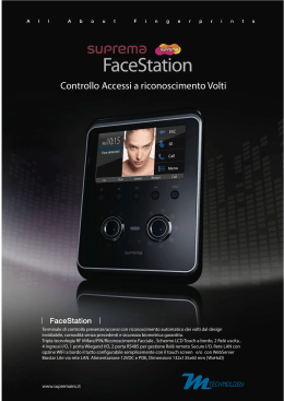
Thermoumidostat
Termoumidostato
Users manual
Manuale Utente
VERSION
VERSIONE
1.0
INSTRUCTION FOR USE
ISTRUZIONI PER L'USO
Avvertenze
Warnings
SAFETY WARNINGS
AVVERTENZE PER LA SICUREZZA
Read this manual carefully before installing and/or using
the equipment and keep it in an accessible place.
Le g g e re co n at te n z i o n e q u e s to l i b re t to p r i m a
dell’installazione e/o dell’uso dell’apparecchiatura e
conservarlo in un luogo accessibile.
The manufacturer’s technical office can be contacted on
the numbers shown on the back of this manual for queries
or special technical requests.
L’ufficio tecnico del Costruttore si rende disponibile
ai numeri indicati sul retro del presente libretto per
consulenze o richieste tecniche particolari.
•
CAUTION
Installation and maintenance must only be carried out by
qualified personnel, otherwise the warranty will decay.
• Use original spare parts only: disregarding this rule
invalidates the warranty.
•
ATTENZIONE
L’installazione e la manutenzione vanno eseguiti solo da
personale qualificato pena il decadimento della Garanzia.
• Esigere solo ricambi originali: la mancata osservazione di
questa norma fa decadere la garanzia.
DISPOSAL
SMALTIMENTO
In accordance with the provisions of the
following European directives, 2002/95/EC,
2002/96/EC 2003/108/EC, regarding reducing
the use of hazardous substances in electrical
and electronic equipment, in addition to waste
disposal.
In base a quanto previsto dalle seguenti
direttive europee 2002/95/CE, 2002/96/CE e
2003/108/CE, relative alla riduzione dell’uso
di sostanze pericolose nelle apparecchiature
elettriche ed elettroniche, nonché allo
smaltimento dei rifiuti.
The crossed-out rubbish bin symbol shown on the equipment
indicates that, at the end of its useful life, the product must be
collected separately from other waste.
The user must therefore dispose of the above equipment at the
end of its useful life at an appropriate centre for the collection of
electronic and electro-technical waste, or return it to the dealer
when purchasing a similar new device in terms of one to one.
Appropriate separate waste collection for subsequent sending
of the disused equipment for recycling, treatment and
compatible environmental disposal contributes to preventing
possible negative effects on the environment and favours
recycling of the materials of which the equipment is composed.
The abusive disposal of the product by the user leads to the
application of the penalties envisaged by current regulations
regarding the matter.
Il simbolo del cassonetto barrato riportato sull’apparecchiatura
indica che il prodotto alla fine della propria vita utile deve essere
raccolto separatamente dagli altri rifiuti.
L’utente dovrà, pertanto, conferire l’apparecchiatura giunta a
fine vita agli idonei centri di raccolta differenziata dei rifiuti
elettronici ed elettrotecnici, oppure riconsegnarla al rivenditore
al momento dell’acquisto di una nuova apparecchiatura di tipo
equivalente, in ragione di uno a uno.
L’adeguata raccolta differenziata per l’avvio successivo
dell’apparecchiatura dismessa al riciclaggio, al trattamento e allo
smaltimento ambientale compatibile contribuisce ad evitare
possibili effetti negativi sull’ambiente e sulla salute e favorisce
il riciclo dei materiali di cui è composta l’apparecchiatura.
Lo smaltimento abusivo del prodotto da parte dell’utente
comporta l’applicazione delle sanzioni previste dalla vigente
normativa in materia.
3
Indice
Description
Descrizione
Pagina
Warnings
Avvertenze
3
Safety warnings
Avvertenze per la sicurezza
3
Disposal
Smaltimento
3
Introduction
Description
Introduzione
Descrizione
5
5
Interfaccia utente e modalità
6
Description of the display
Descrizione del display
6
Description of the key
Descrizione dei tasti
7
Regulation Symbol
Simboli per regolazione
8
User interface and modes
Installation
Installazione
9
Assembly
Montaggio
9
Accessories and dipswitches
Accessori e Dipswitch
10
Electrical connection
Configuration
Collegamenti elettrici
Configurazioni
10
11
Operating Modes
Modo di funzionamento
11
Main parameter to be set
Parametri principali da impostare
12
Addictional functions
Funzionalità aggiuntive
13
Functions
Funzioni
16
(T+H) Temperature and humidity control
(T+H) Regolazione di Temperatura e umidità
16
(T2A+H) Automatic temperature and humidity control
(T2A+H) Regolazione automatica di temperatura e
umidità
17
Table of parametr
Tabella dei parametri
20
Alarms and signals
Allarmi e segnalazioni
25
Technical specifications
Caratteristiche tecniche
26
Technical specifications
Caratteristiche tecniche
26
Wiring
Cablaggi
26
4
Introduzione
Introduction
DESCRIPTION
DESCRIZIONE
The thermostat-humidostat terminal is an instrument that can,
according to the model chosen, control the room temperature
and humidity.
It can be used in various operating modes, which are described in
this manual. Depending on the model, the following functions/
components are included:
• Built-in NTC temperature and humidity sensor with digital
measurement. Available on all humidostat codes, not available
on thermostat-only codes.
• Digital input from voltage-free or 24 Vac contact, with control
function for alarms, on/off , etc.
• 0 to 10 V output for controlling humidifiers, air-conditioners or
condensing units.
• Two relay outputs with class 2 insulation from the rest of the
instrument for controlling the actuators.
• Advanced algorithms for operation in heating, cooling or
automatic mode. Special functions for the control of underfloor
heating, radiant floors in cooling mode and temperature
compensation functions. Timer and RTC clock for day and night
operation
• Display in degrees Celsius/Fahrenheit
Il terminale termostato umidostato CLIMA è uno strumento che
consente, a seconda del modello scelto, la regolazione della
temperatura e dell’umidità di un ambiente.
Può essere utilizzato in varie modalità di funzionamento che
verranno descritte in questo manuale. A seconda del modello
contiene le seguenti funzioni/componenti:
•Sonda di temperatura NTC e di umidità con misura digitale
all’interno del controllo. Presente in tutti i codici umidistato,
non presente nei codici solo termostato.
•Ingresso digitale a contatto o con tensione applicata di
24 Vac, con funzione di comando per allarmi, accensione,
spegnimento ecc.
•Uscita in tensione da 0 a 10 V per il comando di umidificatori,
condizionatori o motocondensanti.
•Due uscite a relè con isolamento in classe II rispetto al resto
dello strumento per il comando degli attuatori.
•Algoritmi avanzati per il funzionamento in modalità invernale,
estiva o automatica. Funzioni speciali per il controllo del
riscaldamento a pavimento, pavimenti radianti in modalità
raffrescamento e funzioni di compensazione di temperatura.
Timer e clock RTC per funzionamento giorno e notte
•Funzione visualizzazione gradi Celsius/Farenheit
CONTROLLERS
CONTROLLI
Modo Descrizione
Mode Description
T+H
Temperature and humidity control. One relay is
associated with the temperature (R1), the other (R2)
associated with humidification or dehumidification
control. Analogue output associated with the humidity.
T+H
Regolazione di temperatura e umidità. Un relè
associato alla temperatura (R1), l’altro (R2) associato
al controllo di umidifica o deumidifica. Uscita
analogica associata all’umidità.
T2A+H Two-stage temperature and proportional humidity
control with automatic control of the cooling/heating
mode. The two relays (R1 and R2) are associated with
the temperature, the analogue output is associated
with the humidity. Other settings for this mode are
available by parameter. See the chapter “Functions”
T2A+H Regolazione di temperatura a doppio stadio e
controllo proporzionale dell’umidità con regolazione
automatica della modalità estate/inverno. I due relè
(R1 e R2) sono associati alla temperatura, l’uscita
analogica è associata all’umidità. Altre impostazioni
per questo modo disponibili via parametro. Si veda
il capitolo ‘“Funzioni”
HARDWARE DESCRIPTION
DESCRIZIONE HARDWARE
• 2 AI temperature:
instrument, remote
opt.
• 1 Humidity sensor
• 2 DO: relay outputs
(R1 &R2)
• 1 DI: voltage-free
contact
• 1 AO: 0/10 V voltage
• 1 clock with backup
• 2 AI di temperatura:
interna, esterna opz.
• 1 Sonda umidità
• 2 DO: uscite relè (R1 e R2)
• 1 DI: contatto pulito
• 1 AO: tensione
0...10 V
• 1 orologio con
backup
It performs temperature and humidity
control in manual or automatic mode with
time bands. Based on the set parameters,
the thresholds for the activation of the
relays and the analogue output are selected,
according to the temperature measured by
the instrument.
This model has an internal clock and
operation with time bands can be set, 2 bands
a day, the same for all 7 days of the week. In
the event of power failures the time is stored
for a maximum of 2 days.
5
Svolge la regolazione di temperatura e
umidità in modalità manuale o automatica
con fasce orarie. In base ai parametri
impostati si scelgono le soglie di attivazione
dei relè e dell’uscita analogica in base alla
temperatura e umidità misurate dallo
strumento.
Permette di impostare il funzionamento
a fasce orarie, 2 fasce al giorno, uguali
per tutti i 7 giorni della settimana. In caso
di mancanza dell’alimentazione l’ora è
mantenuta per un massimo di 2 gg.
Interfaccia utente e modalita’
User interface and modes
The figures below show the display and the representation of the
corresponding symbols.
Le figure riportano il display con la rappresentazione dei relativi
simboli
DESCRIPTION OF THE DISPLAY
DESCRIZIONE DEL DISPLAY
2
1
3
4
5
6
7
11
10
9
8
Description
Descrizione
1
LARGE field - It displays the temperature/humidity;
Campo LARGE - Visualizza temperatura/umidità;
2
Mode for setting the active value on the large display;
Modalità impostazione setpoint della grandezza attiva su
display grande;
3
Night mode symbol. If off = daytime mode;
Segnalazione modalità di funzionamento notturno. Se
spento = modalità diurna;
Lock mode
Modalità lock
4
. The parameter is not accessible;
. Il parametro non è accessibile;
5
Active time bands;
Fasce orarie attive;
6
Outside/inside/maximum/minimum temperature symbol;
Segnalazione temperatura esterna/interna/massima/
minima;
7
Mode for setting the active value on the small display;
Modalità impostazione setpoint della grandezza attiva su
display piccolo;
8
Auto operating mode;
Modalità di funzionamento auto;
9
SMALL field - It displays the temperature/humidity;
Campo SMALL - Visualizza temperatura/umidità;
10
11
Dehum. (
) /humid. (
) operation. When the ramp Funzionamento deum. (
) /umid. (
symbol is on the corresponding mode is active;
la relativa modalità è attiva;
Heating (
) /cooling (
) operation. When the ramp
symbol is on the corresponding mode is active. In the clima
models with 2 relays, the 2 segments come on independently.
In the clima models with 1 relay the 2 segments are either
both on or off .
6
). Rampa accesa
Funzionamento Inverno ( ) /Estate (
). Rampa accesa
la relativa modalità è attiva. Con i clima a 2 relè si attivano
i 2 segmenti in modo indipendente. Con i clima ad 1 relè i
2 segmenti sono entrambi accesi o spenti.
DESCRIZIONE DEI TASTI
DESCRIPTION OF THE KEY
Key
Tasto
Descrizione
Description
CLIMA controller On/Off . If the remote ON/OFF digital input Accensione/spegnimento del controllo CLIMA. In caso
is connected, the function of the key may be disabled.
di presenza dell’ingresso digitale ON/OFF da remoto, la
funzione del tasto può essere inibita.
It selects the temperature display mode, Celsius or Fahrenheit Seleziona la modalità di visualizzazione della temperatura
degrees. Whenever pressed it switches the temperature units. tra gradi Celsius e Fahrenheit. Ad ogni pressione
corrisponde una commutazione sulla temperatura.
Permette di visualizzare ed eventualmente cambiare
Used to display and where necessary change, using the
tramite i tasti UP
e DOWN
il setpoint visualizzato
and
keys, the set point displayed in the SMALL field.
If held for more than 5 sec accesses the parameters sul campo SMALL.
Se premuto per più di 5 sec si accede al menù
menu.
To scroll the various parameters use and . To edit hem parametri.
e
. Per
press the
key a second time and to exit the parameters Per scorrere i vari parametri utilizzare
modificarli premere una seconda volta il tasto
e per
menu press the
key. Access to the parameters is protected
uscire dal menù parametri premere il tasto
. L’accesso
by password if parameter PS is enabled.
ai parametri è sotto password se è abilitato il parametro
relativo PS.
Change mode manually: activates the opposite function (and Cambio di stato manuale: attiva la funzione inversa (e il
the corresponding set point) to the current (night if day or day sepoint relativo) rispetto a quella attuale (night se si è in
if night), for the set time. To change or reset the timer use the modalità day o day se si è in modalità night), per il tempo
and
keys to increase or decrease the time. Press a impostato. Per cambiare o azzerare il timer utilizzare i
second time to exit and return to the main menu.
tasti
e
per incrementare o decrementare il tempo.
If sleep mode is already active, pressing the key shows the Premere una seconda volta per uscire e tornare al menù
time remaining on the timer.
principale.
E.g..: if the clima is in Night mode (moon symbol on) from Se la modalità sleep è già attiva premendo il tasto si vede
time band, pressing this key activates daytime mode (moon il tempo residuo alla scadenza del timer.
symbol off ) for the set time.
Es.: se il clima è in Night (simbolo luna attivo) da fascia
oraria, premendo questo tasto si attiva la modalità day
(simbolo luna spento) per il tempo che si imposta.
It accesses the menu for setting the clock, the time bands, Accede al menù per l’impostazione del clock, delle fasce
and the default value of the timer. When first pressed displays orarie, e del valore di default del timer. Alla prima pressione
the current time (RTC); to display the other parameters, use del tasto visualizza l’ora attuale (rtc) per visualizzare gli altri
the
and
arrows. To set a new value, press
when parametri utilizzare le frecce
e . Per l’impostazione
displaying the desired parameter and change the value using di un nuovo valore premere
quando è visualizzato il
the
and
keys. Press a second time to exit and return parametro di interesse e cambiare il valore tramite i tasti
to the main menu.
e .
Premere una seconda volta per uscire e tornare al menù
principale.
It accesses the menu to display the temperatures. Press the Accede al menù per la visualizzazione delle temperature,
key repeatedly. Their meaning is displayed in the box with per visualizzarle si prema più volte il tasto. Il loro significato
the home symbol.
è visualizzato sul riquadro con il simbolo della casa.
It also displays the value of the analogue output when “Out” Visualizza inoltre il valore assunto dall’uscita analogica alla
is shown in the SMALL field.
comparsa di “Out” nel campo small del display
From the main menu it increases the value of the set point Da menù principale incrementa il valore di setpoint
displayed in the LARGE field.
visualizzato sul campo grande.
In the other menus it displays the variables or the parameters, Dagli altri menù visualizza le variabili o i parametri oppure
or alternatively sets the value after having pressed
.
ne modifica il valore se preceduto dalla pressione del
tasto
.
From the main menu it decreases the value of the set point Da menù principale decrementa il valore di setpoint
displayed in the LARGE field.
visualizzato sul campo grande.
In the other menus it displays the variables or the parameters, Dagli altri menù visualizza le variabili o i parametri oppure
or it alternatively sets the value after having pressed
ne modifica il valore se preceduto dalla pressione del
tasto
7
SIMBOLI PER REGOLAZIONE
REGULATION SYMBOLS
Key
Simb.
Descrizione
Description
Summer functioning mode. Dehumidification function is Modalità di funzionamento estiva. Viene automaticamente
automatically associated.
associata la funzione di deumidifica.
Summer functioning mode. Temperature is higher than the
setpoint, and the temperature relay has a closed contact.
The 2 steps are activated independently (considering the
distance to the setpoint).
Modalità di funzionamento estiva. La temperatura
è superiore rispetto al setpoint e il relè relativo alla
temperatura ha il contatto chiuso. I 2 gradini sono
attivati indipendentemente (in funzione della distanza
dal setpoint).
Winter functioning mode. Temperature is lower than the Modalità di funzionamento invernale. La temperatura
setpoint, and the temperature relay has a closed contact.
è inferiore rispetto al sepoint e il relè relativo alla
temperatura ha il contatto chiuso.
Winter functioning mode. Temperature is lower than the
setpoint, and the temperature relay has a closed contact.
The 2 steps are activated independently (considering the
distance to the setpoint).
Modalità di funzionamento invernale. La temperatura
è inferiore rispetto al setpoint e il relè relativo alla
temperatura ha il contatto chiuso.
I2 gradini sono attivati indipendentemente (in funzione
della distanza dal setpoint)
Automatic functioning mode. See the list of the available Modalità di funzionamento automatica. Si veda l’elenco
versions to get to know the different functioning modes.
dei modelli disponibili, per conoscere le varie modalità
di funzionamento.
Dehumidification functioning mode. It is automatically
associated to summer functioning, and it includes
temperature control. It can be selected by positioning the
dip switch 4 with off.
Modalità di funzionamento deumidifica. È associata
automaticamente al funzionamento estivo. Se presente
anche il controllo di temperatura, altrimenti è selezionabile
mettendo il dip switch 4 su off.
Dehumidification functioning mode. Humidity is higher than Modalità di funzionamento deumidifica, l’umidità è
the setpoint and the humidity relay has a closed contact.
superiore rispetto al setpoint e il relè relativo all’umidità
ha il contatto chiuso.
Humidification functioning mode. It is automatically
associated to winter functioning, and it includes temperature
control. It can be selected by positioning the dip switch 4
with on.
Modalità di funzionamento umidifica. È associata
automaticamente al funzionamento invernale. Se
presente anche il controllo di temperatura, altrimenti è
selezionabile mettendo il dip switch 4 su on.
Humidification functioning mode. Humidity is lower than the
setpoint and the humidity relay has a closed contact or the
ramp for analogue output is activating. Activation symbol
flashes more and more often, while analogue output value
increases. With100% the ramp is always on.
Modalità di funzionamento umidifica. L’umidità è inferiore
rispetto al setpoint e il relè relativo all’umidità ha il
contatto chiuso o la rampa analogica d’uscita comincia
ad attivarsi. Il simbolo dell’attuazione lampeggia con
una frequenza sempre maggiore col crescere del valore
dell’uscita analogica. Con uscita al 100% la rampa è
costantemente accesa.
8
Installation
Installazione
Below you will find a description of the recommended operations
for correct installation.
Si riportano qui di seguito le operazioni consigliate per una
corretta installazione.
ASSEMBLY
MONTAGGIO
Open the product by detaching the front part from the mounting
base, as shown down:
• Using a screwdriver, remove the screw holding the tab in the
opening.
• Once having removed the screw, slide the plastic tab as shown
in the figure so as to remove it from the instrument and be able
to lever the catch.
• To open the instrument, press the tab on the front by inserting
a flathead screwdriver into the slit in the middle on the bottom
of the case and at the same time flip the front panel upwards.
Aprire il prodotto staccando la parte frontale dalla basetta di
montaggio come mostrato sotto:
•Tramite un cacciavite svitare il tassello posto sull’apertura.
•Una volta rimossa la vite far scivolare il tassello di plastica
come mostrato in figura in modo da toglierlo dallo strumento
e poter far leva sull’incastro.
•Per aprire lo strumento, premere la linguetta della parte
frontale inserendo un cacciavite a lama piatta nella feritoia al
centro del lato inferiore della scatola e contemporaneamente
ruotare verso l’esterno il frontale facendo perno sulla parte
superiore.
°C /F
°C F
Se t
Se t
Pr g
Pr g
• Once having completely removed the cover of the instrument,
the two parts remain connected by a flat cable that can be
disconnected from the front panel.
• Fasten the bottom of the clima to the wall using the screws
contained in the packaging. For drilling, use the template on the
rear of the packaging.
• To connect the wires to the terminal block, remove the terminal
covers by squeezing the two fins.
• Make the required connections according to the model chosen,
running the connection cables through the hole in the middle
of the bottom shell and connecting them to the terminal block,
observing the indications on the label. Separate the connection
and control cables from the relay cables. The wiring diagrams
are shown in paragraph electrical connections.
•Tolto completamente il coperchio dello strumento le due parti
rimangono collegate tramite un cavetto a flat che può essere
scollegato sul lato frontale.
•Fissare il fondo del clima al muro tramite le viti contenute
nella confezione. Per la foratura puo’ essere utilizzata la dima
sul retro coperchio dell’imballo
•Per collegare i fili alla morsettiera rimuovere il coprimorsetti
agendo sulle due alette di aggancio.
•Eseguire i collegamenti desiderati secondo il modello scelto
facendo passare i cavi di collegamento nel foro centrale del
guscio inferiore e collegarli all’apposita morsettiera facendo
attenzione a rispettare le indicazioni riportate sull’etichetta.
Separare i cavi di connessione e comando da quelli dei relè.
Si riportano nel paragrafo collegamenti elettrici gli schemi di
collegamento elettrico.
Important: Make sure all the power supply lines have been
connected, both low voltage (24 Vac/dc) and, where necessary,
high voltage for the relays (230 V), before reconnecting the front
part of the instrument using Front-Rear flat cable.
Attenzione: È importante assicurarsi di aver collegato
tutte le linee di alimentazione, sia in bassa tensione (24 Vac/
dc) che eventualmente alta tensione per i relè (230 V) prima di
riconnettere la parte frontale dello strumento tramite il FLAT
Front-Rear.
Nota: Ai fini della sicurezza elettrica (EN60730-1), una volta
completato il montaggio del controllo, avvitare la linguetta
plastica nell’apposito alloggio posto per l’apertura dello
strumento.
Note: For the purposes of electrical safety (EN60730-1), once the
controller has been installed, tighten the plastic tab in the housing
for opening the instrument.
9
ACCESSORI E DIPSWITCH
ACCESSORIES AND DIPSWITCHES
Dip-switches
FLAT Front-Rear
Connector
Description
FLAT
Front-rear
The flat front/rear connection cable must be reconnected Il cavo flat di connessione frontale/retro deve essere
in the position defined by the plastic part to ensure correct ricollegato con la posizione ed orientamento definiti
polarity
dal particolare plastico (polarizzatore)
Descrizione
Dipswitches For configuring operation and cooling / heating, Per la configurazione dei modi di funzionamento e la
humidification / dehumidification modes
modalità estate/inverno, umidifica/deumidifica
COLLEGAMENTI ELETTRCI
ELECTRICAL CONNECTION
Dehumidification
consent *
Consenso
deumificazione *
1
Temperature
consent
Consenso
temperatura
3
Power
supply
2
4
G0
24V~
1VA,50/60Hz
G
22–35V
Humidification
0-10V output
Uscita 0-10V
umidificazione
6
8
9
Digital input
10
R1
1(1)A
5
7
G0
R2
1(1)A
10
* In the second configuration with
T2A+H functioning the relay n. 2
turns into an automatic season
change contact.
Nella configurazione 2 del
funzionamento in T2A+H il
relè 2 diventa contatto cambio
stagione automatico.
Configurazioni
Configurations
MODO DI FUNZIONAMENTO
Before closing the instrument again, the chosen model must be
configured.
See the table of settings allowed for the possible configurations
according to the model purchased.
Prima di richiudere lo strumento è necessario scegliere la
configurazione per il modello scelto.
Si veda la tabella delle regolazioni consentite per le configurazioni
possibili secondo il modello acquistato.
Important: The configurations not allowed for the specific
hardware can be selected, yet obviously should be avoided,
as not all the operations are available; the installer is responsible
for checking that this will not cause operating problems in the
installation.
See the chapter on “Functions“ for a detailed description of each
individual operating mode.
Attenzione: Le configurazioni non previste dal
modello hardware specifico possono comunque essere
selezionate, ma sono, ovviamente, da evitare in quanto non
tutte le attuazioni sono disponibili, ed è a carico dell’installatore
verificare che ciò non causi problemi di funzionamento
dell’impianto.
Si veda il capitolo “Funzioni“ per una descrizione dettagliata di
ogni singola modalità di funzionamento.
SETTING ALLOWED FOR EACH MODEL
REGOLAZIONI CONSENTITE PER MODELLO
Dip 1
Dip 2
Dip 3
Model
Modello
OPERATING MODES
On
On
Off
T+H
Temperature and humidity control. One relay
(Standard) is associated with the temperature (R1), the
other (R2) associated with humidification or
dehumidification control. Analogue output
associated with the humidity.
Regolazione di temperatura e umidità. Un relè
associato alla temperatura (R1), l’altro (R2)
associato al controllo di umidifica o deumidifica.
Uscita analogica associata all’umidità.
On
On
On
T2A+H
(Advanced
Avanzata)
Two-stage temperature and proportional
humidity control with automatic control of the
cooling/heating mode. The two relays (R1 and
R2) are associated with the temperature, the
analogue output is associated with the humidity.
Other settings for this mode are available by
parameter. See the chapter ‘‘Functions”.
Regolazione di temperatura a doppio stadio
e controllo proporzionale dell’umidità con
regolazione automatica della modalità estate/
inverno. I due relè (R1 e R2) sono associati alla
temperatura, l’uscita analogica è associata
all’umidità. Altre impostazioni per questo
modo disponibili via parametro. Si veda il
capitolo “Funzioni”.
Descrizione
Description
DIPSWITCH CONFIGURATION
CONFIGURAZIONE DIP SWITCH
The 4 dipswitches are used to set the instrument for the control
mode.
Mediante i 4 dip-switch si predispone lo strumento per la
modalità di regolazione.
Dip 1,2,3
Dip 4
Control mode as in the above table
Modo di regolazione come da tabella soprastante
OFF – cooling/dehumidification
OFF – estate/deumidifica
ON – heating/humidification
ON – inverno/umidifica
11
MAIN PARAMETERS TO BE SET
PARAMETRI PRINCIPALI DA IMPOSTARE
The parameters for each operating mode also feature a default
value, and these values can be restored by running the “Factory
set” operation.
The default values are the same for all eight modes. See the table
of parameters for details of the default values and settings.
Tutti i parametri sono preimpostati ad un valore di default, e
possono sempre essere ripristinati eseguendo l’operazione di
“Factory set”.
I valori di default sono uguali per tutti gli otto modi. Vedere la
tabella parametri a pagina 20 per dettagli dei valori di default
e impostazione.
Per l’impostazione iniziale è necessario verificare/impostare
almeno i seguenti parametri:
•SETPOINT: in funzione della modalità di funzionamento
scelta sono utilizzati diversi set point. Per impostarli tutti è
necessario entrare (tramite il tasto
- 5 secondi) nella
modalità impostazione parametri e settare i valori relativi.
Con i tasti
e
si accede direttamente alla modifica del
Campo Grande.
Con una leggera pressione del tasto
si accede la Campo
Piccolo si utilizzano poi i tasti
e
per modificare i valori.
Initially at least the following parameters need to be checked/set:
•SETPOINT: depending on the operating mode, different set points
are used. To set these, access (
key - 5 seconds) the mode for
setting the parameters and set the corresponding values.
With the keys
and
you can directly access to Big Field
change.
By pressing softly the key
you can access to Small Field. Use
then the keys
and
to change values.
The following set points need to be defined:
• set point for temperature control
- Daytime (def. 20.0 °C) and night set point (def. 18.0 °C) in heating
- Daytime (def. 24.0 °C) and night set point (def. 26.0 °C) in cooling
• set point for humidity control
- Humidification set point (def. 30.0 % RH)
- Dehumidification set point (def. 70.0 % RH)
I setpoint da configurare sono:
•set point per la regolazione di temperatura
- Set Invernale Diurno (def. 20,0 °C) e Notturno (def. 18,0 °C)
- Set Estivo Diurno (def. 24,0 °C) e Notturno (def. 26,0 °C)
•set point per la regolazione dell’umidità
- Set Umidificazione (def. 30,0 % U.R.)
- Set Deumidificazione (def. 70,0 % U.R.)
•OROLOGIO, FASCE ORARIE
: Premuto il relativo tasto è
possibile visualizzare ed eventualmente modificare la durata
di default del timer cambio di stato, visualizzare o modificare
l’orologio rtC e impostare l’ora delle fasce di Day e Night.
•Clock, TIME BANDS
): Press the corresponding key to display
and if necessary set the default duration of the change mode
timer, display or set the RTC clock and set the Day and Night
time bands.
rtC
clock hh:mm
rtC
orologio hh:mm
SLP
manual changeover duration
def. 8 hours
SLP
durata cambio manuale
def. 8 ore
dAy
start day band
def. 08:00
dAy
inizio fascia diurna
def. 08:00
nlt
start night band
def: 20:00
nlt
inizio fascia notturna
def: 20:00
Once having displayed the desired parameter using the
/
keys, press SET and the parameter starts flashing.
Edit the value using the
/
keys and then press SET.
To exit the menu, press the PRG key again.
To disable the time bands function, set parameter rtC off :
Una volta visualizzato il parametro che si desidera modificare
tramite i tasti / si prema il tasto Set ed il parametro inizia
a lampeggiare. Modificare il valore tramite i tasti / e poi
premere il tasto Set. Per uscire dal menù si prema di nuovo
il tasto Prg. Per disabilitare la funzione fasce orarie si metta il
parametro rtC in modalità OFF:
• Select parameter rtC using
and set the value using the
key.
• When reaching 00:00 using the
key the function will be off.
When parameter rtC is set to off the operating mode is always
daytime, and consequently only the daytime set points are used,
•Selezionare il parametro rtC con tasto
e modificare il
valore con tasto .
•Al raggiungimento del valore 00:00 con tasto si seleziona
lo stato Off
Con il parametro rtC impostato OFF la modalità di
funzionamento è sempre quella diurna, vengono quindi
utilizzati solo i set point diurni, quelli notturni sono presi in
the night settings are only used when the
key is pressed,
manually changing mode.
The same is true for models without the RTC function.
When the time bands are set, the symbol is shown on the
display.
considerazione esclusivamente agendo sul tasto attivando
il cambio di stato manuale. Lo stesso vale per i modelli che non
hanno disponibile la funzione orologio rtC.
Quando le fasce orarie sono impostate compare il simbolo
sul display.
12
•PARAMETERS: check/set the other parameters (dIF, dS1,...) based
on the mode used.
•PARAMETRI: verificare/impostare altri parametri (dIF, dS1,...)
specifici per il modo utilizzato.
The controller is then ready for operation:
• Start control by pressing the key (or activating the digital
input, if featured).
Il controllo è quindi pronto per il funzionamento:
•Attivare le regolazioni con il tasto (o con il comando da
ingresso digitale se previsto).
Note: The values of the parameters are specific for each individual
operating mode (T+H, T2A+H), the user can therefore defined
a different set of parameters for each of the 8 control modes.
The specific set of parameters will be loaded by the clima when
changing the configuration of the dipswitches.
Nota: I valori dei parametri impostati sono specifici di ogni
singolo modo di funzionamento (T+H, T2A+H), l’utilizzatore
può quindi predefinire per ogni modo un set di parametri
diverso per ognuna delle 8 modalità di regolazione. Il set di
parametri specifico verrà caricato dal clima alla configurazione
dei dip-switches.
ADDITIONAL FUNCTIONS
FUNZIONALITÀ AGGIUNTIVE
CHANGE NIGHT/DAY MODE MANUALLY
MODALITÀ CAMBIO MANUALE NIGHT/DAY
This activates the opposite function to the current (night if day or
day if night), for the set time.
Il cambio di stato attiva la modalità operativa contraria rispetto
a quella attiva in quel momento (day se siamo in night e night
se siamo in day) e la mantiene attiva per il tempo impostato.
Pressing the key once you can access the timer menu and display
the duration.
To change the duration of the temporary mode use the / keys.
To change the value of the timer permanently, access the Prg
menu and set parameter SLP. To set the current timer to zero and
Tramite la prima pressione del relativo tasto
si accede al
menù timer ed è visualizzato il tempo di durata.
Per variare la durata del modo temporaneo utilizzare i tasti
/ .
Per cambiare il valore del timer in modo permanente accedere
al menù Prg e variare il parametro SLP. Per azzerare il timer
del modo temporaneo in esecuzione e riportare lo strumento
return the instrument to the original mode, press the
key, the
remaining time is displayed, then press until reaching the value
0. The instrument, after having briefly displayed the message OFF
SLP, automatically returns to the main menu. Once having set the
alla modalità originaria premere il tasto , viene visualizzato
il tempo rimanente, premere quindi
fino al raggiungere il
valore 0. Lo strumento, dopo avere brevemente visualizzato
l’informazione OFF SLP ritorna automaticamente al menù
principale. Una volta impostato il timer ad ogni pressione del
timer, pressing the key displays the time remaining on the timer.
This value can be changed at any time.
To exit the menu press the
key again.
tasto
viene visualizzato il tempo rimanente alla scadenza
del timer. È possibile modificare questo valore in qualsiasi
momento.
Per uscire dal menù premere nuovamente il tasto
Example of operation with time bands:
Esempio di funzionamento con le fasce orarie:
RTC: presente e configurato, sono le 15:55, viene attivato il
RTC: fitted and configured, the time is 15:55, the symbol is on
dAy: 8:00
nIt: 16:00
At 16:00 the controller will switch to Night mode with a lower (in
heating) or higher (in cooling) temperature setting. Assuming the
user wants to extend Day mode for a further 3 hours, having to
work late in the office.
simbolo
dAy: 8:00
nIt: 16:00
Alle 16:00 il controllo passerà in modalità Night con set di
temperatura ridotto (se siamo in regolazione invernale) o
maggiorato (se in regolazione estiva). Supponiamo che l’utente
voglia prolungare il funzionamento Day per altre 3 ore, deve
far tardi in ufficio.
The following operations are required:
• press the key;
• set the timer to 3h and 00’ using the
• press the
.
key;
Le operazioni da fare sono:
key to confirm the setting.
•premere il tasto ;
•impostare il timer a 3h e 00’ tramite il tasto
The clima returns to Day mode with the corresponding set point.
It will automatically return to Night mode according to the time
bands when the timer reaches zero.
•premere il tasto
;
per confermare l’impostazione.
Il clima torna a lavorare in modalità Day col setpoint relativo.
Tornerà automaticamente alla modalità Night voluta dalle fasce
orarie allo scadere del timer.
13
FUNCTIONS THAT CAN BE ASSOCIATED WITH THE DIGITAL INPUT
FUNZIONI ASSOCIABILI ALL’INGRESSO DIGITALE
According to the model chosen, the digital input can be connected
to:
• a voltage-free ON/OFF contact;
• a 24 Vac voltage signal with optically-isolated reference.
A seconda del modello scelto è possibile collegare all’ ingresso
digitale:
•un contatto ON/OFF pulito;
•un segnale in tensione 24 Vac con riferimento optoisolato.
The digital input can be used for the functions listed in the table.
These are selected by setting parameter dI from the parameters
menu. Parameter POL is used to define the polarity of the contact.
The digital input has priority over all other settings as regards the
function it has been enabled for. That is, if dI = 3, the digital input is
L’ingresso digitale può essere utilizzato per le funzioni elencate
in tabella e la selezione avviene tramite l’impostazione del
parametro dI dal menù parametri mentre il parametro POL
permette di definire la polarità del contatto.
L’ingresso digitale ha priorità su tutti (tastiera, supervisore)
per la funzione specifica per cui è stato abilitato. Ovvero, se ad
esempio, con dI = 3, si vuole poter impostare la selezione Day/
used to select Day/Night mode, pressing the
key will have no
affect. If attempting to control the function enabled by the digital
Night tramite ingresso digitale, la pressione del tasto risulterà
ininfluente. Se si tenta di modificare, tramite tasto, la funzione
abilitata tramite ingresso digitale il clima mostrerà
input using a key, the clima will show the symbol to indicate
that the operation is disabled.
The humidifier alarm dl=4 is immediate, with automatic reset and
signal only (no action on the outputs).
Code Description
il simbolo ad indicare che l’operazione non è consentita.
L’allarme umidificatore dl=4 è immediato con reset automatico
e di sola segnalazione (non agisce sulle uscite).
Descrizione
Range Default
OFF...4
dI
Digital input configuration
OFF: disabled
1: select remote cooling/heating
2: remote ON/OFF
3: select day/night (alternative set point)
4: remote alarm
Configurazione ingresso digitale
OFF: disabilitato
1: selezione remota estate/inverno
2: ON/OFF remoto
3: Selezione giorno/notte (set alternativo)
4: Allarme remoto
POL
Digital contact polarity
Used to choose whether to consider the digital
input active when closed or open or alternatively
whether or not there is voltage in the opticallyisolated version.
Voltage-free contact:
nE: active when the input is closed
PO: active when the input is open
Optically isolated:
nE: active when voltage is present at the input
PO: active when voltage is not present at the input
Polarità contatto Digitale
nE, PO
Consente di scegliere se considerare l’ingresso
digitale attivo quando è chiuso o aperto oppure
quando è presente o meno tensione nella
versione optoisolata.
Contatto pulito:
nE: attivo quando l’ingresso è chiuso
PO: attivo quando l’ingresso è aperto
Optoisolato:
nE: attivo quando è presente tensione in ingresso
PO: attivo quando non è presente tensione in
ingresso
OFF
nE
SENSOR CALIBRATION
CALIBRAZIONE SENSORI
To make up for any errors due to the length of the cables or the
sensors connected, the controller features two parameters for
calibrating the values read by the sensors.
Per tenere conto di eventuali errori dovuti alla lunghezza dei cavi
o delle sonde collegate, il controllo è provvisto di due parametri
che calibrano la lettura delle sonde.
The following parameters are involved:
Parametri interessati sono i seguenti:
Code
CAL + Int
CAL + HUn
Description
Descrizione
Range
Default UOM
Inside temperature calibration, digital Calibrazione Temperatura interna della -10...10
sensor or NTC
sonda digitale o NTC
Within a maximum of ± 10 °C
Entro un massimo di ± 10 °C
0.0
°C
Digital humidity sensor calibration.
Within a maximum of ± 15% rH
0.0
% U.R.
Calibrazione sonda umidità digitale.
Entro un massimo di ± 15% U.R.
14
-15...15
PASSWORD
PASSWORD
On all models a password can be set for accessing the parameters,
using parameter PS. Once the value of parameter PS has been set
(other than zero), this value must be entered in order to access the
parameters.
Tutti i modelli consentono l’impostazione di una password (PS)
per l’accesso ai parametri. Una volta impostato il valore di PS
(diverso da zero), per poter accedere ai parametri è necessario
re-inserire il valore precedentemente memorizzato.
Note: Make sure the password is kept in a safe place, as without
it the parameters can no longer be accessed. The value can only
be reset from the supervisor or using the parameter copying key.
Nota: Fare attenzione a custodire la password, poiché la
sua perdita non consente più di accedere ai parametri dello
strumento. Il ripristino è possibile solo da supervisore o
mediante chiave copia parametri.
Code
PS
Description
Descrizione
Range
Password for accessing the parameters
Set to 0: no password is required to access the parameters.
Set other than zero: the same value must be entered to access the parameters.
0...999
Default UOM
0
-
Parametro Password per accesso parametri
Impostato a 0: non viene richiesta password per accesso a parametri.
Impostata diversa da zero: si deve re-inserire lo stesso valore per accedere ai parametri.
ANTIFREEZE
ANTIGELO
To prevent the formation of ice and frost, the controller features the
antifreeze function, which activates the relay dedicated to the
temperature function regardless of the control mode, when in
heating operation.
Antifreeze is available in all control modes, apart from humidity
only, and the corresponding relay is activated when the
temperature falls below 5 °C. The function is also active when the
instrument is off and is enabled 20 seconds after shutdown.
Per prevenire la formazione di ghiaccio, il controllo è provvisto
della funzione antigelo che attiva il relè dedicato alla
temperatura indipendentemente dalla modalità di regolazione
se è in funzionamento invernale. La modalità antigelo funziona
con tutte le regolazioni fuorché quella di sola umidità e attiva
il corrispondente relè quando la temperatura è sotto i 5 °C. La
funzione è attiva anche quando lo strumento è in OFF e viene
attivata 20 secondi dopo lo spegnimento.
15
Funzioni
Functions
This chapter describes the temperature and humidity control
modes available.
The control modes for the different models of clima are based
on a set of parameters, divided into two levels:
•Level 1, basic: main settings, always required;
•Level 2, advanced: used to customise the features of the
controller.
In questo capitolo sono descritte le modalità di regolazione
previste per la temperatura ed umidità.
Le regolazioni per i diversi modelli di clima sono basate su un
set di parametri diviso su due livelli:
•Livello 1, base: impostazioni principali, sempre necessarie;
•Livello 2, avanzato: consentono di personalizzare i dettagli della regolazione.
(T+H) TEMP. AND HUMIDITY CONTROL
(T+H) REGOLAZIONE DI TEMP. E UMIDITÀ
It is used in simple applications, with one stage for the temperature
and one for the humidity, to send a start signal to an air-conditioner
or heat pump/boiler via the relay. The analogue output is only
activated in humidification mode.
Dipswitch configuration:
dip1: ON
dip2: ON
dip3: OFF
Control is available in both cooling and heating (dip4).
È utilizzata in un’applicazione semplice con uno stadio per la
temperatura e uno per l’umidità per dare il consenso ad un
condizionatore o pompa di calore/caldaia tramite il relè. L’uscita
analogica è attivata soltanto in modalità umidifica.
Configurazione dip:
dip1: ON
dip2: ON
dip3: OFF
La regolazione è prevista sia per estate che inverno (dip4).
STANDARD CONFIGURATION / CONFIGURAIONE STANDARD
DIP 4 = ON
DIP 4 = OFF
Output
Output
dS1
dIF
Temp.
Winter setpoint
Set point invernale
Output
dS1
dFH
dSA
dIF
Temp.
Summer setpoint
Set point estivo
Output
R2
dFH
Temperature
Temperatura
R1
R1
Humidity
Umidità
R2
% U.R.
dFd
% U.R.
Humidify setpoint
Dehumidify setpoint
Set point umidifica Set point deumidifica
Temperature (top) and humidity control mode (bottom).
Modalità di regolazione temperatura (in alto) e umidità (in
basso)
BASIC PARAMETRES FOR SETTING T+H
PARAMETRI BASE IMPOSTAZIONE T+H
Code
Codice
dIF
dS1
dSA
dFH
dFd
Default
LE
Value or link if LE = 1
Valore o legame se LE = 1
set point estivo diurno
24,0 °C
1
-
night set point in cooling
set point estivo notturno
26,0 °C
1
-
day set point in heating
set point inverno diurno
20,0 °C
1
-
night set point in heating
set point invernale notturno
18,0 °C
1
-
relay differential
relay off set
analogue output off set
differenziale relè
offset relè
offset uscita analogica
1,0 °C
0,0 °C
0,0 %
1
2
2
=0
=0
humidification set point
set point umidifica
50,0 %
1
-
dehumidification set point
set point deumidifica
70,0 %
1
-
humidification differential
dehumidification differential
differenziale umidifica
differenziale deumidifica
5,0 %
5,0 %
1
1
-
Description
Descrizione
day set point in cooling
16
ADVANCED CONFIGURATION / CONFIGURAIONE AVANZATA
(T2A+H) AUTOMATIC TEMPERATURE AND
HUMIDITY CONTROL
(T2A+H) REGOLAZIONE AUTOMATICA
DI TEMPERATURA E UMIDITÀ
This operating mode can be used to perform two types of control
(be selected by parameter Adc):
• automatic cooling/heating selection for systems with airconditioner and boiler, with humidifier control
• reverse-cycle systems with heating and cooling set point and
humidifier control.
Attraverso questo modo di funzionamento è possibile eseguire
due tipi di regolazione (selezionabili da parametro Adc):
•selezione automatica estate/inverno per sistemi con
condizionatore e caldaia con controllo umidificatore
•sistemi reversibili con setpoint invernale ed estivo e controllo
umidificatore.
Dipswitch configuration:
dip1: ON
dip2: ON
dip3: ON
Configurazione dip:
dip1: ON
dip2: ON
dip3: ON
CONFIGURATION 1 (ADC =1) - DIP 4 HAS NO EFFECT
CONFIGURAZIONE 1 (ADC =1) - DIP 4 ININFLUENTE
The typical application is the control of a classic system with air
conditioner + boiler and humidity control using a proportional
humidifier.
Dehumidification is performed using the air-conditioner, making
sure that the temperature conditions are within the comfort limits.
L’applicazione tipica è il controllo di un classico impianto
con condizionatore + caldaia con regolazione di umidità
proporzionale.
La deumidifica è attuata attraverso il condizionatore, verificando
che le condizioni di temperatura siano all’interno dei limiti di
comfort.
There are two humidity set points, one for humidification and the
other for dehumidification; the changeover points for automatic
humidification/dehumidification operation are also defined.
I setpoint di umidità sono due, uno per l’umidifica e l’altro per la
deumidifica e definiscono anche i punti di cambio di stato per
il funzionamento automatico di umidifica/deumidifica.
There is just one temperature set point for both cooling and
heating, the changeover (cooling/heating) occurs based on the
activation points of the two outputs.
Il setpoint di temperatura è unico per estate/inverno mentre il
cambio di stato della regolazione (estate/inverno) avviene in
corrispondenza dei punti di attivazione delle due uscite.
Dehumidification can only be activated if the humidity exceeds
the dehumidification set point plus the differential dFd, and
furthermore:
Temp > Set – dS1 – dF2
La richiesta di deumidifica può essere attuata solo se, l’umidità
supera il set point di deumidifica più il differenziale dFd e anche:
Temp > Set – dS1 – dF2
It is deactivated if the humidity is below the dehumidification set
point and in furthermore: Temp < Set – dS1 – dF2 – 0.5 °C
Si disattiva se l’umidità è sotto il set point deumidifica e anche:
Temp < Set – dS1 – dF2 – 0.5 °C
17
See the following graph for the description of this operating mode.
Si veda il seguente grafico per la descrizione di questa modalità
di funzionamento.
Output
R1
dF2
R1
dS1
dS1
Temperature
Temperatura
dIF
Temp.
Winter / Summer temperature setpoint
Set point temperatura inverno/estate
Output
ADVANCED CONFIGURATION / CONFIGURAIONE AVANZATA
10 V
Output
R2
0V
% U.R
dFH
dFd
dSA
Humidify setpoint
Set point umidifica
% U.R.
Dehumidify setpoint
Set point deumidifica
PARAMETRI BASE CONFIGURAZIONE 1 (ADC = 1)
BASIC PARAMETRES FOR CONFIGURATION1 (ADC = 1)
Code
Codice
Humidity
Umidità
Default
LE
Value or link if LE = 1
Valore o legame se LE = 1
set point diurno (unico)
20,0 °C
1
-
night set point (same)
set point notturno (unico)
18,0 °C
1
-
dIF
relay 1 differential
differenziale relè 1
1,0 °C
1
-
dIF2
relay 2 differential
differenziale relè 2
0,5
2
= dIF
dS1
relay off set
offset relè
0,0 °C
1
-
dSA
analogue output off set
offset uscita analogica
0,0 %
2
=0
humidification set point
set point umidifica
50,0 %
1
-
dehumidification set point
set point deumidifica
70,0 %
1
-
dFH
humidification differential
differenziale umidifica
5,0 %
1
-
dFd
dehumidification differential
differenziale deumidifica
5,0 %
1
-
-
Description
Descrizione
day set point (same)
18
CONFIGURATION 2 (ADC =2) - DIP 4 HAS NO EFFECT
CONFIGURAZIONE 2 (ADC = 2) - DIP 4 ININFLUENTE
For the control of a classic reverse-cycle air-conditioning system,
with automatic cooling/heating changeover and proportional
humidity control.
Automatic operating mode is signalled on the display by the AUTO
symbol, next to the set point.
There are two set points, one for cooling and the other for heating,
and both can be set, the mode switches between cooling and
heating automatically according to the room temperature
measured.
The two set points are set by pressing the
key or the
/
key, first the cooling set point is displayed and then the heating set
point, the controller automatically checks that there is a difference
of at least 1°C between the two set points.
Relay 1 controls the heating/cooling signal.
The analogue output controls humidification.
Relay output 2 manages the changeover in mode.
Per il controllo di un classico impianto di condizionamento
reversibile, con change-over estate/inverno automatico e con
regolazione di umidità proporzionale.
La modalità di funzionamento di tipo automatico è segnalata
sul display attraverso il simbolo di AUTO a fianco del setpoint.
I setpoint sono due uno per l’estate e l’altro per l’inverno
entrambi impostabili, mentre il cambio di modo estivo/
invernale avviene in automatico in funzione della temperatura
ambiente misurata.
L’impostazione dei due set point avviene premendo il tasto
oppure uno dei tasti
/ , compare prima il setpoint estivo
e poi quello invernale, viene verificato che tra i due set point ci
sia una differenza minima di almeno 1 °C.
Il relè 1 serve per dare il consenso caldo/freddo.
L’uscita analogica controlla l’umidificazione.
L’uscita relè 2 è per il change-over.
See the following graph for the description of this operating mode.
Si veda il seguente grafico per la descrizione di questa modalità
di funzionamento.
Output
Output
R1
dF2
R1
dS1
Temp.
Winter setpoint
Set point inverno
10 V
dS1
Summer setpoint
Set point estate
Output
R2
0V
dFH
dSA
% U.R
Humidify setpoint
Set point umidifica
Winter setpoint
Set point inverno
Summer setpoint
Set point estate
Temp.
PARAMETRI BASE CONFIGURAZIONE 2 (ADC = 2)
BASIC PARAMETRES FOR CONFIGURATION2 (ADC = 2)
Code
Codice
Temp.
dIF
Default
LE
Value or link if LE = 1
Valore o legame se LE = 1
set point estivo diurno
24,0 °C
1
-
night set point in cooling
set point estivo notturno
26,0 °C
1
-
day set point in heating
set point inverno diurno
20,0 °C
1
-
night set point in heating
set point invernale notturno
18,0 °C
1
-
dIF
relay 1 differential in cooling
differenziale relè 1 in raffrescamento
1,0 °C
1
-
dIF2
relay 1 differential in heating
differenziale relè 1 in riscaldamento
1,0 °C
2
= dIF
dS1
relay 1 offset
offset relè 1
0,0 °C
2
=0
dSA
analogue output off set
offset uscita analogica
0,0 %
2
=0
humidification set point
set point umidifica
50,0 %
1
-
dehumidification set point
set point deumidifica
70,0 %
1
-
humidification differential
differenziale umidifica
5,0 %
1
-
dFH
Description
Descrizione
day set point in cooling
19
Tabella parametri
Table of parameters
Code
Description
Descrizione
Range
day temperature set point in cooling
set point di temperatura estivo diurno
night temperature set point in cooling
set point di temperatura estivo notturno
day temperature set point in heating
set point di temperatura invernale diurno
night temperature set point in heating
set point di temperatura invernale notturno
single day temperature set point for automatic modes
set point di temperatura unico diurno per i modi automatici 10...50 20.0 °C
single night temperature set point for automatic modes
set point di temperatura unico notturno per i modi automatici 10.. 50 18.0 °C
dIF
dF2
dS1
dFA
dSA
EHI
ELo
Set point di umidifica
Dehumidification set point
Set point di deumidifica
dFH
dFd
10...50
24,0
°C
10...50
26,0
°C
10...50
20,0
°C
10...50
18,0
°C
10...50
20,0
°C
10...50
18,0
°C
1,0
°C
1,0
°C
Temperature differential for relay 1
This is an absolute value and is added to or subtracted from the set point depending on the
control mode, cooling or heating.
0,1...10
Differenziale di temperatura relè1
È un valore assoluto e si somma o si sottrae al setpoint in relazione al modo di regolazione
estiva o invernale.
Temperature differential for relay 2.
This is an absolute value and is added to or subtracted from the set point depending on the
control mode, cooling or heating.
0,1...10
Differenziale di temperatura relè2.
È un valore assoluto e si somma o si sottrae al setpoint in relazione al modo di regolazione
estiva o invernale.
Temperature off set for relay 1
This value is added to or subtracted from the set point based on the active control mode. It may
be positive or negative, so as to offer complete flexibility in the position of the step.
-10...10
Off set temperatura relè1
È un valore che viene sommato o sottratto al setpoint in relazione al modo di regolazione
attivo. Può prendere segno positivo o negativo in modo da offrire completa flessibilità
nella posizione del gradino.
Analogue output differential
This value is added to or subtracted from the set point according to the control mode selected,
cooling or heating.
10...80
Differenziale uscita analogica
Si somma o si sottrae al valore di setpoint in funzione al modo di regolazione, estivo o
invernale, selezionato.
Analogue output off set from to the set point
This value is added to or subtracted from to the set point according to the operating mode,
cooling or heating.
0...50
Off set uscita analogica rispetto al set point
Questo valore è sommato o sottratto al setpoint in relazione al modo di funzionamento,
estate o inverno.
Not used
Non usato
Not used
Non usato
Humidification set point
Humidity differential for the activation of the analogue output and the relay.
Differenziale di umidità per l’attivazione dell’uscita analogica e il relè.
Dehumidification differential for the activation of the relay.
Differenziale di deumidifica per l’attivazione del relè.
20
Default UOM
0,5
°C
40
°C
10
°C / %
10...70
50,0
%
10...70
70,0
%
1...20
5,0
%
1...20
5,0
%
SFH
AUt
CSt
Parameter to define the humidification/dehumidification status in day and night mode
It activates or deactivates humidification or dehumidification control (based on DIP 4) with
the time bands.
The parameter can have the following three values
0 - Time bands disabled.
The humidification/dehumidification control is always active, if featured, and is configured
in relation to dip4
1 - Time bands enabled:
When switching to the daytime band, humidification/dehumidification control (depending
on dip4) is activated.
When switching to the night band, humidification/dehumidification control (depending on
dip4) is deactivated.
2 - Time bands enabled:
When switching to the daytime band, humidification/dehumidification control (depending
on dip4) is deactivated.
When switching to the night band, humidification/dehumidification control (depending on
dip4) is activated.
0...2
Parametro per definire lo stato umidifica/deumidifica in modalità diurno e notturna
Attiva o Disattiva la regolazione dell’umidifica o deumidifica (in base a DIP 4) con le fascie
orarie.
Il parametro può assumere i seguenti tre valori:
0 - Fasce orarie disabilitate.
La regolazione di umidifica/deumidifica è sempre attiva, se prevista, ed è configurata in
relazione al dip4
1 - Fasce orarie abilitate:
Alla commutazione nella fascia diurna la regolazione di umidifica/deumidifica (dipende
dal dip4) viene attivata.
Alla commutazione nella fascia notturna la regolazione di umidifica/deumidifica (dipende
dal dip4) viene disattivata.
2 - Fasce orarie abilitate:
Alla commutazione nella fascia diurna la regolazione di umidifica/deumidifica (dipende
dal dip4) è disattivata.
Alla commutazione nella fascia notturna la regolazione di umidifica/deumidifica (dipende
dal dip4) è attivata.
Humidity set point automatically compensated by the outside temperature
If humidity control is featured, the room humidity is controlled with an automatic set point,
defined from 1H to 7H using the keys, as specified in the corresponding table (see page 15).
If set to OFF the mode is disabled.
Setting one of the levels in the table, the controller independently sets a humidity set point in
relation to the outside temperature.
OFF
Livello di set point umidità autocompensato con la temperatura esterna
Se prevista la regolazione di umidità, l’umidità ambiente viene regolata con un setpoint 1H...7H
automatico definibile da 1H a 7H tramite tasti, come specificato nella tabella relativa (si
veda pagina 15).
Se impostato a OFF la modalità è disabilitata.
Impostando uno dei livelli previsti nella tabella il controllo provvede ad impostare
autonomamente un setpoint di umidità in relazione alla misura di temperatura della
sonda esterna.
Parameter for set point compensation
Parameter CSt enables and sets the gain for set point compensation according to the outside
temperature.
If CSt = 0 compensation is disabled.
Also see parameters Ctt and CtS.
-1...1
Parametro per compensazione set point
Il parametro CSt abilita ed imposta il guadagno della compensazione del setpoint in
funzione della temperatura esterna.
Se CSt = 0 la compensazione è disabilitata.
Si vedano inoltre i parametri Ctt e CtS.
21
0
-
OFF
-
0,0
°C
CdF
Ctt
CtS
AdC
dyS
rtc
SLP
dAy
nlt
dI
Max differential for the compensated set point
The maximum value for the compensated set point is limited by this parameter. In heating
mode, if the difference calculated for set point compensation is higher than CdF, the instrument
uses CdF as the maximum difference from the set point.
Similarly, in cooling mode if the difference calculated for set point compensation is less than
CdF, the instrument uses CdF as the maximum difference from the set point.
Differenziale max per il set point compensato
Il valore massimo per il setpoint compensato è limitato da questo parametro. In modalità
invernale se il differenziale del set point di compensazione calcolato risulta maggiore di
CdF, lo strumento assume CdF come differenza massima del set point.
Analogamente, in modalità estiva se il differenziale del setponti di compensazione calcolato
risulta inferiore a CdF, lo strumento assume CdF come differenza massima del set point.
Not used
Non usato
Not used
Non usato
For temperature + humidity control (T2A+H):
Configuration 1: temperature control with set point and dead band only (2xdS1). Two set
points for humidity.
Configuration 2: temperature and humidity control with cooling and heating set point and
automatic changeover.
Per regolazione di temperatura + umidità (T2A+H):
Configurazione 1: regolazione di temperatura con set point unico e banda morta (2xdS1).
Due set point per l’umidità.
Configurazione 2: regolazione di temperatura ed umidità con setpoint estivo ed invernale
e change-over automatico
Active display configuration
Used to set the values shown in the large and small fields on the display
Configurazione display attiva
Consente l’impostazione di visualizzazione nel campo grande e piccolo del display
Current time
The large field displays the hours and the small field the minutes
Orario attuale orologio
Sul campo grande è visualizzato il valore dell’ora su quello piccolo quello dei minuti
Duration of manual day-night mode changeover
The large field displays the hours and the small field the minutes (15 minute steps)
Durata cambio manuale modalità diurna-notturna
Sul campo grande è visualizzato il valore dell’ora su quello piccolo dei minuti (step di 15
minuti)
Day band threshold
The large field displays the hours and the small field the minutes (15 minute steps)
Soglia fascia diurna
Sul campo grande è visualizzato il valore dell’ora su quello piccolo dei minuti (step di 15
minuti)
Night band threshold
The large field displays the hours and the small field the minutes (15 minute steps)
Soglia fascia notturna
Sul campo grande è visualizzato il valore dell’ora su quello piccolo dei minuti (step di 15
minuti)
Digital input configuration
OFF: disabled
1 select remote cooling /heating
2 remote ON/OFF
3 select day/night(set alternative)
4 remote alarm
Configurazione ingresso digitale
OFF: disabilitato
1 selezione remota estate /inverno
2 ON/OFF remoto
3 Selezione giorno/notte (set alternativo)
4 Allarme remoto
22
0...20
2,0
°C
1...2
1
°C
1...4
1
°C
00:00
23:59
00:00
hh:mm
0...12
8
h
00:00
23:59
08:00
hh:mm
00:00
23:59
20:00
hh:mm
OFF...4
OFF
-
POL
EI
EI
LIn
CAL + Int
Digital contact polarity
Used to choose whether to consider the digital input active when closed or open or alternatively
whether or not there is voltage in the optically-isolated version.
Voltage-free contact:
nE: active when the input is closed
PO: active when the input is open
Optically isolated:
nE: active when voltage is present at the input
PO: active when voltage is not present at the input
Polarità contatto digitale
Consente di scegliere se considerare l’ingresso digitale attivo quando è chiuso o aperto
oppure quando è presente o meno tensione nella versione optoisolata.
Contatto pulito:
nE: attivo quando l’ingresso è chiuso
PO: attivo quando l’ingresso è aperto
Optoisolato:
nE: attivo quando è presente tensione in ingresso
PO: attivo quando non è presente tensione in ingresso
Control cooling/heating operating mode
It enables to define the operating mode, cooling/heating, by parameter rather than by DIP 4.
dIS: Parameter EI is disabled, cooling/heating mode is selected by DIP 4 on the rear.
En: Parameter EI is enabled, cooling/heating mode is selected by parameter EI.
Modalità controllo funzionamento estate/inverno
Abilita la possibilità di definire la modalità estate/inverno da parametro anziché da DIP 4.
dIS: Il parametro EI è disabilitato, la modalità estate/inverno è selezionata dal DIP 4 sul retro.
En: Il parametro EI è abilitato, la modalità estate/inverno è selezionata dal parametro EI.
Select cooling/heating operation
It selects the mode, cooling or heating. This parameter is only active if this mode is enabled by
the previous parameter.
E: The instrument works in cooling mode
I: The instrument works in heating mode
Seleziona la modalità estate inverno.
Programmazione funzionamento estate inverno attivo soltanto se si è abilitata questa
modalità tramite il parametro precedente.
E: Lo strumento funziona in modalità estiva
I: Lo strumento funziona in modalità invernale
Instrument output control mode
Enabling this parameter allows the outputs to be controlled directly via the serial connection.
Warning, if enabled no control is performed independently by the instrument. If active and
the supervisor does not query the instrument for more than two minutes, the outputs are
automatically disabled and the no link error (ELn) is signalled on the display.
no: The function is disabled. yES: The function is enabled.
Modalità controllo uscite strumento
Abilitando questo parametro si avrà il controllo delle uscite direttamente da seriale.
Attenzione se abilitato nessuna regolazione è eseguita autonomamente dallo strumento.
Se attiva e il supervisore non interroga lo strumento per più di due minuti, le uscite sono
automaticamente disabilitate e viene segnalato errore di no link (ELn) sul display.
no: la funzione è disabilitata. yES: la funzione è abilitata.
Inside temperature calibration, digital sensor or NTC
Within a maximum of ± 10 °C
Calibrazione temperatura interna della sonda digitale o NTC
Entro un massimo di ± 10 °C
CAL + HUn
Digital humidity sensor calibration.
Within a maximum of ± 15% rH
Calibrazione sonda umidità digitale.
Entro un massimo di ± 15% U.R.
23
nE, PO
nE
-
dIS, En
dIS
-
E, I
E
-
no, yES
no
-
-10...10
0,0
°C
-15...15
0,0
%
LE
LOC
Parameter access level
Level of access the control parameters for the active mode:
Level 1: basic access, only the essential parameters for correct operation.
Level 2: advanced access, used to set all the parameters for the selected control mode.
Livello accesso parametri
Accesso ai parametri di regolazione per il modo attivo:
Livello 1: accesso di base, soltanto i parametri essenziali per il corretto funzionamento.
Livello 2: accesso avanzato, consente di impostare tutti i parametri per la regolazione
selezionata.
Lock
The lock parameter used to disable some functions of the instrument, as per the following
settings:
LOC = OFF
LOC = 1: The UP/DOWN and time bands keys are disabled
LOC = 2: Only the time bands key is disabled
In these cases, the LOCK symbol is shown on the display whenever attempting to perform an
unauthorised operation.
Lock
Il parametro lock serve per inibire alcune funzioni dello strumento come dalle seguenti
impostazioni:
LOC = OFF
LOC = 1: Vengono bloccati i tasti UP/DOWN e fasce orarie
LOC = 2: Viene bloccato soltanto il tasto fasce orarie
In tal caso il simbolo LOCK appare sul display ogni qualvolta si cerca di eseguire
un’operazione non autorizzata.
Unt
Add
SEr
PS
FAC +
SET
1
-
OFF...2
OFF
°C, °F
°C
1...207
1
-
0...999
0
-
no, yES
no
-
Temperature display mode
It sets the temperature display mode, in degrees Fahrenheit or Centigrade. Unlike direct selection
using the key, if changing the temperature display mode using parameter Unt, this becomes
the default display mode when switching the instrument on.
Modalità visualizzazione temperatura
Imposta la modalità di visualizzazione della temperatura in gradi Fahrenheit o Centigradi.
A differenza della selezione tramite tasto diretto, se si cambia la modalità di visualizzazione
di temperatura tramite il parametro Unt questa diventa la modalità di visualizzazione attiva
di default all’accensione dello strumento.
nED
1, 2
Not used
Non usato
RS485 serial address (the external option code IROPZ48500 is required). The address can be
read by the supervisor and can only be changed with direct access on the instrument.
Indirizzo per seriale RS485 (è necessaria l’opzione esterna IROPZ48500). Solo leggibile dal
supervisore mentre per la modifica è necessario accedere dallo strumento.
Not used
Non usato
Password for accessing the parameters
Set to 0: no password is required to access the parameters.
Set other than zero: the same value must be entered to access the parameters.
Parametro password per accesso parametri
Impostato a 0: non viene richiesta password.
Impostata diversa da zero: si deve re-inserire lo stesso valore per accedere ai parametri.
Factory set
Reset the default values (manufacturer) on the instrument for the current mode.
Factory set
Ripristina i valori di default (fabbrica) dello strumento per il modo attivo in quel momento.
Nota: il simbolo ”+” significa che il parametro è rappresentato su
2 campi.
Note: the “+” symbol means that the parameter is shown on 2
fields.
24
Allarmi e segnalazioni
Alarms and signals
Below you will find the table of alarms.
Note: When the value is not shown in the SMALL or LARGE field,
three dashes “---“ are displayed.
Di seguito viene riportata la tabella allarmi.
Nota: Quando non è disponibile la misura sul campo SMALL o
LARGE del display compaiono tre trattini “---“.
Code Description
Codice Descrizione
EE
Eth
E1
Effect
Effetto
system/memory error
it stops all outputs
errore sistema / memoria
blocca tutte le uscite
temperature+humidity sensor fault
it stops all outputs and disables the calculation of the dewpoint
sonda temperatura+umidità guasta
blocca tutte le uscite e disabilita il calcolo del punto di
rugiada
built-in NTC temperature sensor fault
it stops all outputs
sonda temperatura NTC interna guasta
blocca tutte le uscite
remote temperature sensor fault
it stops compensation if active, and control on average if
enabled
sonda temperatura esterna guasta
blocca compensazione se attiva, e media di regolazione
se attivata
RTC alarm
-
allarme RTC
-
high control temperature alarm, radiant floor
it stops all outputs
allarme alta temperatura regolazione pavimento radiante
blocca tutte le uscite
low control temperature alarm, radiant floor
it stops all outputs
E2
Ert
EHi
ELo
ELn
ALE
allarme bassa temperatura regolazione pavimento radiante blocca tutte le uscite
serial connection alarm
only active if I/Os managed via serial connection
allarme collegamento seriale
attivo solo se gli I/O sono gestiti via seriale
external alarm from digital input
signal-only alarm from external contact (humidifier)
allarme esterno da ingresso digitale
allarme da contatto esterno di sola segnalazione
(umidificatore)
25
Reset
Man
Auto
Auto
Auto
Auto
Auto
Auto
Auto
Auto
Caratteristiche Tecniche
Technical Specifications
TECHNICAL SPECIFICATIONS
CARATTERISTICHE TECNICHE
Power supply
24 Vac +10 to -15%, 50/60Hz, 1 VA
22 to 35 Vdc, 0.5W
Class 2 safety power supply
Min. cable cross-section 0.5 mm2.
Power supply compatible (G – G0)
Tensione di alimentazione
24 Vac +10...-15%, 50/60Hz, 1 VA
24...32 Vdc, 1W
Alimentazione di sicurezza in classe II
Sezione min. cavo 0,5 mm2.
Alimentazione compatibile (G – G0)
Operating temperature
0T60 °C, 10 to 90% rH not-condensing
Condizioni di funzionamento
0T60 °C, 10...90% U.R. non condensante
Storage temperature
-20T70 °C, 10 to 90% rH not-condensing
Condizioni di immagazzinamento
-20T70 °C, 10...90% U.R. non condensante
Environmental pollution
normal
Inquinamento ambientale
normale
Pollution
degree 2
Grado di Inquinamento
grado II
Software class and structure
A
Classe e struttura del software
A
Type of action
1C
Tipo azioni
1C
Index of protection
IP20
Ball pressure test temperature on
plastic of front casing
125 °C
Grado di protezione contro gli agenti IP20
atmosferici
Classification according to protection
against electric shock
2, to be integrated into class 1 or 2 appliances
Period of stress across the insulating
parts
long
Immunity against voltage surges
category 2
Wire cross-section (mm2)
from 0.5 to 1.5 mm2
Precision of inside temperature
measurement
± 1 °C from 0 to 60 °C
0 to 10 V analogue output, not
isolated, for proportional control
precision ±5%
max load 5 kΩ, max current 2 mA
Relay approval
EN60730-1: NO 1(1)A 250 Vac cos = 0.4, 100,000
cycles
UL-873: NO 1A resistive 24 Vac, 30 Vdc, 100,000
cycles
PILOT DUTY: 24 Vac, peak 15 A, continuous 1 A,
30,000 cycles
Precision of humidity measurement
(in models where featured) range 10
to 90%%
± 3% rH at 25 °C
± 5% rH 0 to 60 °C
Dimensions (mm):
135x86x36mm
Temperatura della “ball pressure test” 125 °C
sulle plastiche dell’involucro frontale
Classificazione secondo protezione
contro scosse elettriche
Periodo sollecitazioni elettriche delle lungo
parti isolanti
Digital input
connection
Analogue output
connection
Relay output
connections
UL specifi cations
for connections
Immunità contro sovratensioni
categoria II
Sezione dei conduttori
da 0,5 a 1,5 mm2
Precisione della misura di
temperatura interna
± 1 °C da 0 a 60 °C
Uscita analogica 0...10 V non isolata
per regolazione proporzionale
precisione ±5%
carico max 5 kΩ, corrente max 2 mA
Omologazioni uscite relè
EN60730-1: NO 1(1)A 250 Vac cos = 0,4,
100.000 cicli
UL-873: NO 1A resistivo 24 Vac, 30 Vdc,
100.000 cicli
PILOT DUTY: 24 Vac, spunto 15 A, continui 1 A,
30.000 cicli
Precisione della misura di umidità
(nei modelli previsti) range 10...90%
± 3% U.R. a 25 °C
± 5% U.R. 0...60 °C
Dimensioni
135x86x36mm
CABLAGGI
WIRING
Digital input
II, da integrare in apparecchi di classe I o II
Ingresso digitale Versione non isolata:
collegamento diretto del contatto pulito; corrente
di chiusura contatto: 3...5 mA.
Versione isolata:
con alimentazione esterna con contatto 24 Vac:
alimentazione esterna di sicurezza in classe II
separata dai 24 Vac dello strumento
Collegamento
Lunghezza massima 10 m, cavo sezione min. 0,5
ingresso digitale mm2.
Collegamento
Lunghezza massima 10 m, cavo sezione min. 0,5
uscita analogica mm2.
Collegamenti
Lunghezza massima 30 m, cavi sezione da 1,5 a
uscite relè
2,5 mm2, isolamento rinforzato in classe II rispetto
allo strumento.
Isolamento principale tra i relè.
Indicazioni
Si utilizzino conduttori di rame omologati per una
UL per le
temperatura di 75 C.
connessioni
Sezione minima AWG 22-14 rigido o flessibile.
Per la chiusura dei morsetti si consiglia di applicare una
coppia di 7 Lb-In per i morsetti di colore nero (SAURO).
Per utilizzare lo strumento in conformità alla normativa
UL-873 è possibile collegare un carico con tensione
massima 24 Vac, classe II, alla uscita relè.
Non-isolated version:
direct connection of the voltage-free contact;
contact closing current: 3 to 5 mA.
Isolated version:
with external power supply to 24 Vac contact: class
2 safety external power supply separate from the 24
Vac power supply to the instrument
Maximum length 10 m, min. cable cross-section
0.5 mm2.
Maximum length 10 m, min. cable cross-section
0.5 mm2.
Maximum length 30 m, cable cross-section from
1.5 to 2.5 mm2, class 2 reinforced insulation from
the instrument.
Basic insulation between the relays.
Use copper wires approved for a temperature of
75 C.
Minimum cross-section AWG 22-14 rigid or flexible.
To tighten the terminals, apply a torque of 7 Lb/In
for the black terminals (SAURO)
To use the instrument in compliance with UL-873, a
load with a maximum voltage 24 Vac, class 2, can
be connected to the relay output.
Avvertenza: Tutti i collegamenti salvo i relè devono essere
connessi a circuiti a bassissima tensione con isolamento
rinforzato.
Warning: All the connections, except for the relays, must be
connected to very low voltage circuits with reinforced insulation.
26
9100205.00 - 06/2011
Scaricare