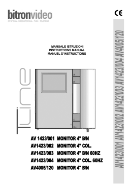
STAFFA PER MONITOR T-LINE
ISTRUZIONI INSTALLAZIONE E PROGRAMMAZIONE PER IMPIANTI €BUS
T-LINE MONITOR BRACKET
ETRIER POUR MONITEUR T-LINE
INSTRUCTIONS D’INSTALLATION ET DE PROGRAMMATION POUR SYSTEMES €BUS
Bitron Video adotta una politica di continuo sviluppo. Bitron Video
si riserva il diritto di effettuare modifiche e miglioramenti a qualsiasi
prodotto descritto nel presente documento senza preavviso.
AV1423/012
INSTALLATION AND PROGRAMMING INSTRUCTIONS FOR €BUS SYSTEMS
Bitron Video follows a policy of continuous evolution of its products.
Therefore Bitron Video reserves the right to introduce changes or
modifications all its products in any moment and without prior
notice.
Bitron Video applique une mèthode de dèveloppement continu.
Par conséquent, Bitron Video se réserve le droit d’apporter des
changements et des améliorations à tout produt décrit dans ce
document, sans aucun préavis.
AV 1423/012 STAFFA €BUS
AV 1423/012 BRACKET FOR T-LINE €BUS MONITOR
AV 1423/012 ETRIER POUR MONITEUR T-LINE €BUS
BITRON VIDEO s.r.l.
Via Torino 21/B - 10044 PIANEZZA (Torino) Italy
Tel. +39 011 968.46.11 (r.a.) - Fax +39 011 968.46.18
http://www.bitronvideo.com
e-mail : [email protected]
012175884.00
1
1
COLONNA/RISER/COLONNE
SW1
Q1
Q1
Q2
Q2
LD
P
T
C
E
B
A
3
1
H
4
AV 1423/012 +
AV 1423/001
P
1
F
( SD 55 )
3
2
SEGR.
AK 7513
1
AB31ABABABAB
2
segreto
8
AV 1423/012 +
AV 1423/001
off
J1
1
ON
12345678
PER LA FUNZIONE DEGLI INTERRUTTORI
VEDI MANUALE ISTRUZIONI
FOR SW TICH FUNCTION
SEE THE INSTRUCTIONS MANUAL
POUR LA FUNCTION DES COMMUTATEUR
VOIR LE MANUEL D'ISTRUCTIONS
L
H
o ff/on
J1
segreto
TASTO CHIAMATA AL PIANO
CALL BUTTON AT THE FLOOR
TOUCHE D'APPEL D'ETAGE
12345678
Q1
Q1
Q2
Q2
LD
P
T
C
E
B
A
3
1
off
1,5 m
L
SW1
H
SW1
L
Au
Au
4
AV 1407/020
doppino twistato
twisted pair
couple tressÈs
128 64 32 16
8
4
2
1
OFF
S1
3
Filo/Wire
1/3
Filo/Wire
C/E/T/P
Filo/Wire
A-B
Filo/Wire
+/-/al/al-
mt.
mm2
mm2
mm2
mm2
50
0,75
0,50
0,30
1,50
100
1,50
0,75
0,30
twisted
200
2,50
1,00
0,30
twisted
Gancio
Hook
Crochet
012175884.00
4
012175884.00
( SD 55 )
3
2
1
AB31ABABABAB
Distanza
Distance
Fili da tagliare
Wires to be cut
Fils a couper
2
AK 7513
Tabella Sezioni Conduttori
Wire section
Section conducteur
Segreto
Secrecy
Secret
ON
ULTIMA / LAST / DERNIERE
eventuale filo di autoeccitazione
possible self-lighting wire
eventuelle fil de autoallumage
Connettore di Chiusura
Senza Collegamenti
Connettore Bus
Con Collegamenti
Closure Connector
without connection
BUS Connector
with connection
Connecteur Fermeture
sans connections
Connecteur BUS
avec connections
15
(SISTEMA “EURO - BUS”)
IMPIANTO VIDEOCITOFONICO 1 POSTO ESTERNO,
1 COLONNA (+ CHIAMATA AL PIANO)
“EURO - BUS” SYSTEM,
VIDEO DOORPHONE SYSTEM WITH 1 VISITOR PANEL,
1 RISER (+ CALL AT THE FLOOR)
SISTEME “EURO - BUS”,
SYSTEME VIDEO 1 ENTREE, 1 COLONNE
(+ APPEL A L’ETAGE)
ITALIANO
All rights reserved - Diritti riservati a Norma di Legge
175 946 72/A
AV 7362
( A 70/IRC )
INSTALLAZIONE
P
NC
N
NA
RETE
MAINS
RESEAU
0
230
1.
2.
R
D
+
_
3.
4.
3C
1
3M
APRIPORTA ESTERNO
EXTERNAL DOOR OP ENER
TOUCHE OUVRE EXTERIEUR
COLLEGAMENTI
serratura
lock
serrure
Sulla staffa è presente una morsettiera che permette il cablaggio dei seguenti segnali:
1:
3:
A:
B:
E:
C:
T:
P:
LD:
Q1, Q1:
Q2, Q2:
Connettore di Chiusura
Senza Collegamenti
SC RC
PER LA FUNZIONE DEI PONTICELLI
VEDI MANUALE ISTRUZIONI
FOR JUMPERS' FUNCTION
SEE THE INSTRUCTIONS MANUAL
POUR LA FUNCTION DES PONTETS
VOIR LE MANUEL D'ISTRUCTIONS
0
+
1/_
AV 0060/00 CH
A
GAVM 3000
B
E
3
Y
Est
Int
CP
X
CD
C2
C1
AP CL
AP
doppino twistato couple tressÈs
twisted pair
B+
I
RI
R
R0
TDE 3000
AV 0086/02E
I fili 1-3-A-B-C devono assolutamente essere collegati per il corretto funzionamento del sistema.
1
2
3
4
8
16
32
64
S
Descrizione dei collegamenti ausiliari
I collegamenti qui descritti, permettono di far svolgere al monitor delle funzioni ausiliarie.
• Il morsetto E, se collegato, permettere di accendere il monitor e la telecamera premendo il tasto
contrassegnato dal simbolo “•“ presente sul monitor. La funzione è disponibile solo se nessun altro monitor
è attivo.
• Il morsetto T, se collegato, permette di accendere il monitor senza attivare la suoneria. Tale funzione è
attivata fornendo una tensione di –12V tra T e 1 quando sul morsetto 3 è presente una tensione di +20V.
• Il morsetto P permette di eseguire la chiamata al piano. Per realizzare tale funzione è indispensabile
utilizzare un alimentatore A70 IRC (AV7362) o aggiungere un alimentatore ausiliario A3000 (AV1142), per
portare il segnale di chiamata ausiliario in colonna.
• Il morsetto LD rende disponibile l’utilizzo del led rosso presente nel monitor. Il led si accenderà collegando
una tensione positiva continua di +12V; tale tensione deve essere riferita alla massa dell’impianto (“1”).
Il led rosso può essere utilizzato quale segnalazione di porta aperta o, collegando il morsetto LD insieme al
morsetto “3”, può indicare l’impegno dell’impianto e quindi l’impossibilità di eseguire l’autoaccensione.
Connettore Bus
Con Collegamenti
AV0045/06E
PSE 3000
Massa di sistema
Positivo alimentazione monitor
Ingresso video negativo
Ingresso video positivo
Autoaccensione monitor
ingresso fonia, chiamata e apriporta.
Ingresso per accensione monitor senza attivazione suoneria.
Ingresso chiamata al piano
Led rosso disponibile sul monitor per segnalazione porta aperta.
Contatto libero NA 24V 0,5A
Contatto libero NA 24V 0,5A
Per il corretto funzionamento del monitor collegare i fili come indicato negli schemi allegati al gruppo video.
Connettore Bus
Con Collegamenti
P1
P2
P3
P4
P5
P6
0
Connettore di Chiusura
Senza Collegamenti
14
Far in modo che la canalizzazione dedicata al cablaggio dell’impianto arrivi in corrispondenza del foro
previsto sulla staffa. L’altezza consigliata è da 1,48 a 1,52 metri dal pavimento finito.
Fissare per mezzo delle 4 viti in dotazione la staffa al muro, facendo coincidere la luce centrale della staffa
con l’eventuale scatola incasso precedentemente murata, o con l’uscita del cavo dal muro.
Collegare i cavi alla morsettiera presente sulla staffa.
Montare il monitore sulla staffa impegnandolo prima sui ganci superiori e quindi ruotandolo fino a
bloccarlo con il gancio di fissaggio automatico. Per toglierlo dalla staffa, premere il gancio indicato nella
figura 3 ed effettuare il movimento inverso.
012175884.00
012175884.00
3
off
J1
segreto
Q1
Q1
Q2
Q2
LD
P
T
C
E
B
A
3
1
H
2
1
Au
Au
AV 1407/020
doppino twistato
twisted pair
couple tressÈs
ULTIMA / LAST / DERNIERE
AK 7513
4
2
1
Tabella Sezioni Conduttori
Wire section
Section conducteur
Filo/Wire
+/-/al/al-
mt.
mm2
mm2
mm2
mm2
50
0,75
0,50
0,30
1,50
Impostazione codice utente
100
1,50
0,75
0,30
twisted
Per mezzo del dip-switch S1 (fig. 4) assegnare un indirizzo univoco all’utente per consentire l’identificazione
della chiamata:
1. annotarsi su un foglio di carta (oppure utilizzare quello che si trova stampato in fondo al libretto del
modulo digitalizzatore), il valore numerico del tasto di chiamata corrispondente a ciascun utente.
2. impostare ciascuna staffa assegnandogli il valore del tasto corrispondente. Per fare ciò occorre settare
opportunamente, eventualmente con l’ausilio di un cacciavite piccolo a taglio (fig. 2), lo switch di
programmazione S1.
Ogni interruttore assume un valore diverso a seconda dalla propria posizione cosi come indicato nella
tabella.
200
2,50
1,00
0,30
twisted
012175884.00
( SD 55 )
3
AB3 1ABABABAB
Filo/Wire
A-B
4
1
SEGR.
3
AB31ABABABAB
o ff/on
4
P
1
F
( SD 55 )
8
AV 1423/012 +
Filo/Wire
C/E/T/P
2)
3)
4)
segreto
AV 1423/001
Filo/Wire
1/3
installare a muro con i tasselli in dotazione, facendo coincidere l’uscita cavi in corrispondenza dell’asola
prevista per l’ingresso cavi;
eseguire il cablaggio come indicato negli schemi di installazione opportuni (vedi schemi allegati)
impostare l’indirizzo dell’utente come descritto nel paragrafo relativo
scegliere la modalità di funzionamento, con o senza segreto per mezzo del ponticello SEGRETO.
off
J1
AV 1423/001
Distanza
Distance
1)
H
AV 1423/012 +
AK 7513
Segreto di conversazione: il ponticello SEGRETO consente di attivare od escludere il segreto di conversazione
audio. Con il ponticello posizionato su “ON” il segreto di conversazione è attivo. Sarà possibile conversare con
il posto esterno soltanto dopo la ricezione di una chiamata.
Con il ponticello posizionato su “OFF” (impostazione di default) il segreto di conversazione è escluso.
Sollevando in qualsiasi momento il microtelefono del monitor, sarà possibile conversare con il posto esterno.
L
SW1
SW1
Q1
Q1
Q2
Q2
LD
P
T
C
E
B
A
3
1
TASTO CHIAMATA AL PIANO
CALL BUTTON AT THE FLOOR
TOUCHE D'APPEL D'ETAGE
12345678
PER LA FUNZIONE DEGLI INTERRUTTORI
VEDI MANUALE ISTRUZIONI
FOR SWTICH FUNCTION
SEE THE INSTRUCTIONS MANUAL
POUR LA FUNCTION DES COMMUTATEUR
VOIR LE MANUEL D'ISTRUCTIONS
In questa configurazione l’ultima staffa in impianto deve essere lasciata con il settaggio standard,
senza tagliare il ponticello per garantire la bassa impedenza in terminazione di linea.
INSTALLAZIONE
SW1
H
Terminazione: la staffa viene consegnata con il settaggio standard di bassa impedenza di ingresso del segnale
video (tipicamente 75Ω). Tagliando i fili indicati in fig. 4 si modifica il valore di impedenza portandola a
47kΩ.
E’ necessario tagliare il ponticello solo sulle staffe montate in impianti senza distributori video, ovvero in
impianti cosiddetti entra/esci in cui i fili A e B arrivano direttamente sui morsetti della staffa e da questa
ripartono verso i monitor successivi.
Si sottolinea, che questa modalità di funzionamento tipica del sistema €BUS Bitron Video, è analoga a
quella di un tradizionale impianto citofonico standard senza segreto di conversazione, a cui moltissimi
utenti sono generalmente abituati. Questo sistema risulta pertanto l’ideale anche per rifacimenti di
impianti esistenti ove l’utenza, abituata ad un certo tipo di funzionamento del sistema, non gradisce
introduzione del segreto di conversazione o di altre caratteristiche tipiche degli impianti €BUS.
L
L
ON
PREDISPOSIZIONI
COLONNA/RISER/COLONNE
12345678
Quando il monitor è acceso, lo stesso led si illuminerà in verde e tale colorazione prevarrà su una eventuale
segnalazione esterna.
Settando adeguatamente il monitor (vedi manuale del monitor), e fornendo una tensione continua di +12V
sul morsetto LD, il led rosso si illuminerà per segnalare l’esclusione di chiamata (MUTE).
• I morsetti Q1 e Q1 rendono disponibili il contatto pulito normalmente aperto del tasto “A” presente sul
monitor. Può essere utilizzato come attivazione per il comando delle luci scale, telecamere , cancelli elettrici
ecc …
• I morsetti Q2 e Q2 rendono disponibili il contatto pulito normalmente aperto del tasto “B” presente sul
monitor. Può essere utilizzato come attivazione per il comando delle luci scale, telecamere , cancelli elettrici
ecc …
012175884.00
eventuale filo di autoeccitazione
possible self-lighting wire
eventuelle fil de autoallumage
13
(SISTEMA “EURO - BUS”)
IMPIANTO VIDEOCITOFONICO 1 POSTO ESTERNO,
1 COLONNA (+ CHIAMATA AL PIANO)
“EURO - BUS” SYSTEM,
VIDEO DOORPHONE SYSTEM WITH 1 VISITOR PANEL,
1 RISER (+ CALL AT THE FLOOR)
SISTEME “EURO - BUS”,
SYSTEME VIDEO 1 ENTREE, 1 COLONNE
(+ APPEL A L’ETAGE)
2
3
4
4
8
5
16
6
32
7
64
8
128
Poiché il codice 13 si ottiene sommando i valori 1, 4 e 8, per impostarlo sul dip switch occorrerà spostare in
posizione OFF, gli interruttori corrispondenti che come risulta dalla precedente tabella sono rispettivamente il
primo il terzo e il quarto interruttore. I rimanenti interruttori sono da lasciare in posizione ON (fig. 2).
OFF-SET =
IPSE 82
AN6215/L
AV 7362
( A 70/IRC )
2
0
R
I
B_
B+
CD
CP
AN9854/8
P1
P2
P3
P4
P5
P6
P7
P8
C
3C
1
3M
( TDE 82 )
R
D
+
_
AN 9847
RESEAU
1
serratura
lock
serrure
P
NC
N
NA
0
230
Valore decimale
1
Esempio di codifica del codice 13 pari a: 1 + 4 + 8 = 13
AN 1364
APRIPORTA ESTERNO
EXTERNAL DOOR OPENER
TOUCHE OUVRE EXTERIEUR
Posizione
Per costruire un qualsiasi codice occorrerà spostare in posizione OFF gli interruttori la cui somma dei valori
danno il codice voluto, lasciando su ON quelli non interessati.
14,5
0
RETE
MAINS
RESEAU
RETE
MAINS
All rights reserved - Diritti riservati a Norma di Legge
175 946 72
P1
P2
P3
P4
L
L
P5
P6
P7
P8
CD 5-8
CD 1-4
Ap
+
_
AN 6074
12
1
3
A
B
V
S
0
CP
CH
CD
9
doppino twistato
twisted pair
couple tressÈs
( GVM 70/.. )
012175884.00
012175884.00
5
ENGLISH
d’un petit tournevis à tête plate).
Chaque interrupteur prend une valeur différente selon sa position (voir illustration au tableau
ci-dessous).
INSTALLATION
1.
2.
3.
4.
Make the system wiring duct reach the hole on the bracket. The recommended height is from 1.48 to 1.52
from the finished floor.
Fasten to the wall using the 4 screws provided and make the central gap of the bracket coincide with
either the previously walled-in embedding box (where applicable) or with the wire protruding from the
wall.
Connect the wires to the terminal board on the bracket.
Fit the monitor to the bracket by engaging the upper hooks first and then turn it to lock it using the
automatic fastener hook. To remove it from the bracket, pressure the fastener shown in figure 3 and
reverse the operation.
CONNECTIONS
A terminal board for wiring the following signals is found on the bracket:
1:
System earth
3:
Monitor power positive
A:
Negative video input
B:
Positive video input
E:
Monitor auto power-on
C:
Audio, call and door opener input
T:
Input for monitor operation without ringer
P:
Floor call input
LD:
Red LED on monitor for open door indication
Q1, Q1: Spare NO contact 24V 0.5A
Q2, Q2: Spare NO contact 24V 0.5A
Connect the wires as show in the diagrams attached to the video unit for correct operation of the monitor.
Position
Valeur décimale
1
1
2
2
3
4
4
8
5
16
6
32
7
64
8
128
Pour élaborer un code quelconque, il est nécessaire de positionner sur OFF les interrupteurs dont la somme des
valeurs donne le code désiré et de positionner sur ON ceux qui ne sont pas concernés par l’opération.
Exemple de codage du code 13 équivalent à : 1 + 4 + 8 = 13
Pour programmer le code 13 qui est obtenu en additionnant les valeurs 1, 4 et 8, il est nécessaire
de positionner sur OFF les interrupteurs correspondants qui, selon le tableau précédent, correspondent
respectivement au premier, au troisième et au quatrième interrupteur. Les interrupteurs restants seront laissés
en position ON (fig. 2).
Wires 1-3-A-B-C must be connected for correct system operation.
Description of auxiliary connections
The connections described here provide the following auxiliary monitor functions.
• Terminal E, if connected, is used to switch the monitor and the camera on by pressing the button with the
“•“ symbol on the monitor. The function is available only if no other monitor is on.
• Terminal T, if connected, is used to switch the monitor on without operating the ringer. This function is
available by supplying -12V voltage between T and 1 when a voltage of +20V is present on terminal 3.
• Terminal P is used to floor calls. A A70 IRC (AV7362) power supply unit is required for this function to take
the auxiliary call signal to the column. Alternatively, use an A3000 (AV1142) auxiliary power supply unit .
• Terminal LD makes it possible to use the red LED on the monitor. The LED will light up when a positive +12V
continuous voltage is applied. This voltage must be referred to the system earth (“1”).
The red LED may be used to indicate open door conditions or, connecting terminal LD to terminal “3” it may
be used to indicate when the system is working and consequently that auto power-on is not possible.
When the monitor is on, the same LED will light up with green light and this colour will prevail on external
indications, if any.
Set the monitor correctly (see monitor manual) and provide +12V direct voltage to terminal LD to make the
red LED light up indicating muting function (MUTE).
• Terminals Q1 and Q1 make the normally open clear contact of button “A” on the monitor available. This
may be used, for example, to operate staircase lights, cameras, electrical gates, etc.
• Terminals Q2 and Q2 make the normally open clear contact of button “B” on the monitor available. This
may be used, for example, to operate staircase lights, cameras, electrical gates, etc.
6
012175884.00
012175884.00
11
Lorsque le moniteur est allumé, la même del s’allume en vert et cette couleur prévaudra sur une éventuelle
signalisation externe.
Après avoir paramétré de façon appropriée le moniteur (voir manuel du moniteur), et fourni une tension
continue de +12V sur la borne LD, la del rouge s’illuminera pour signaler l’exclusion d’appel (MUTE).
• Les bornes Q1 et Q1 libèrent le contact nettoyé et normalement ouvert de la touche “A” située sur le
moniteur. Il peut être utilisé pour activer la commande de l’éclairage du palier, des caméras, des portails
électriques etc …
• Les bornes Q2 et Q2 libèrent le contact nettoyé et normalement ouvert de la touche “B” située sur le
moniteur. Il peut être utilisé pour activer la commande de l’éclairage du palier, des caméras, des portails
électriques etc. …
PRE-REGLAGES
Terminaison: l’étrier est livré avec le paramétrage standard de basse impédance d’entrée du signal vidéo
(généralement 75Ω). En coupant les fils indiqués à la Fig. 4, la valeur d’impédance sera modifiée à 47kΩ.
Il est nécessaire de couper la barrette uniquement sur les étriers montés dans des installations sans distributeur
vidéo, c’est-à-dire dans des installations dénommées entrée/sortie dont les fils A et B arrivent directement sur
les bornes de l’étrier pour repartir vers les moniteurs suivants.
SET-UPS
Termination: The bracket is supplied with the standard video signal input low impedance setting (typically
75Ω). The impedance value may be modified by cutting the wires shown in Fig. 4 taking it to 47kΩ.
Obviously, the jumper only needs to be cut in brackets fitted in systems without video distributor, i.e. in
so-called in/out systems, in which the A and B wires reach the bracket terminals directly and from here depart
towards the monitors.
In this configuration, the last bracket in the system must be left with the standard setting without
cutting the jumper to ensure line termination low impedance.
Conversation privacy: The SECRECY jumper is used to active the audio conversation privacy function. The
conversation privacy function is on when the jumper is in the “ON” position. It will be possible to establish
a conversation with the door panel only after receiving a call.
The conversation privacy function is off when the jumper is in the “OFF” position (default setting). Pick up
the handset at any time to establish a conversation with the door panel.
This typical Bitron Video €BUS operating mode is identical to that of a traditional standard doorphone
system without conversation privacy to which many users are generally accustomed. This system is
consequently ideal for refurbishing existing systems in which users accustomed to a certain type of
operation do not like the introduction of the conversation privacy function or other special €BUS system
features.
Dans cette configuration, aucune modification ne doit être apportée au paramétrage du dernier
étrier de l’installation et la barrette doit rester intacte de manière à garantir la basse impédance en
terminaison de ligne.
Secret de conversation: la barrette SECRET DE CONVERSATION permet d’activer ou d’exclure le secret de
conversation audio. Avec la barrette positionnée sur “ON” le secret de conversation est actif. Il sera possible
de converser avec la platine externe uniquement après réception d’un appel.
Avec la barrette positionnée sur “OFF” (paramétrage par défaut), le secret de conversation est exclu. En
soulevant à tout moment le combiné du moniteur, il sera possible de converser avec la platine extérieure.
Il est souligné que ce mode de fonctionnement, traditionnel du système €BUS Bitron Video, est semblable
à celui d’une installation d’interphones standard sans secret de conversation, auxquels la plupart des
utilisateurs sont généralement habitués. Ce système constitue par conséquent la solution idéale pour les
réfections d’installations existantes, où les utilisateurs, habitués à un certain type de fonctionnement
du système, n’apprécient pas l’introduction du secret de conversation ou de toute autre caractéristique
traditionnelle des installations €BUS.
INSTALLATION
1)
2)
3)
4)
User code setting procedure
Use dip switch S1 (fig. 4) to assign a univocal address to the user for call identification:
INSTALLATION
1.
1)
2.
2)
3)
4)
fixer au mur à l’aide des chevilles fournies en veillant à faire correspondre la sortie des câbles avec l’œillet
prévu pour le passage des câbles ;
exécuter le câblage conformément aux indications des schémas d’installation appropriés (voir schémas
d’installation en annexe)
configurer l’adresse de l’utilisateur en suivant la procédure décrite au paragraphe de référence
choisir la modalité de fonctionnement, avec ou sans secret de conversation au moyen de la barrette
SEGRETO (Secret).
Install on the wall using the bolts provided making the wire outlet corresponds to the slot for wire
entrance.
Wire as shown in the attached installation diagrams (see diagrams).
Set the user’s address as shown in the respective paragraph.
Select the operating mode (with or without privacy) using the SECRECY jumper.
Note the number of the call button corresponding to each user on a sheet of paper or in the form on the
back of the digitiser manual.
Set each bracket by assigning the value of the corresponding button. In order to do this, set the
programming switch S1 accordingly using a small screwdriver if required (fig. 2).
Each switch will assume a different value according to its position, as shown in the table.
Configuration du code utilisateur
Position
Decimal value
1
1
2
2
3
4
Au moyen du dip-switch S1 (fig. 4), attribuer une adresse univoque à l’utilisateur de manière à pouvoir
identifier l’appel:
4
8
5
16
1.
6
32
7
64
8
128
2.
noter sur une feuille de papier (ou utiliser la page imprimée au fond du manuel du module numériseur) la
valeur numérique de la touche d’appel relative à chaque utilisateur.
paramétrer chaque étrier en lui attribuant la valeur de la touche correspondante. Pour ce paramétrage, il
est nécessaire de régler l’interrupteur de programmation S1 de façon appropriée (éventuellement à l’aide
10
012175884.00
012175884.00
7
To form any code, move the switches whose sum results in the required code to the OFF position and leave all
the other switches in the ON position.
FRANÇAIS
Example: code 13: 1 + 4 + 8 = 13
Since 13 is the result of 1 plus 4 plus 8, to set this code on the dip switch firstly shift the corresponding
switches to the OFF position (as shown in the table these are the first, the third and the fourth switch). Leave
the other switches in the ON position (fig. 2).
INSTALLATION
1.
2.
3.
4.
Faire en sorte que la goulotte dédiée au câblage de l’installation arrive en face du trou prévu sur l’étrier.
La hauteur conseillée va de 1,48 à 1,52 mètres à partir du sol fini.
Fixer l’étrier au mur à l’aide des 4 vis fournies, en faisant correspondre l’orifice central de l’étrier et
l’éventuel boîtier d’encastrement avec la sortie du câble hors du mur.
Raccorder les câbles au bornier présent sur l’étrier.
Fixer le moniteur sur l’étrier en l’engageant d’abord sur les crochets supérieurs et en le faisant ensuite
pivoter de manière à le bloquer au moyen du crochet de fixation automatique. Pour l’extraire de l’étrier,
appuyer sur le crochet indiqué dans la figure 3 et appliquer le mouvement inverse.
BRANCHEMENTS
L’étrier est doté d’un bornier qui permet de connecter les signaux suivants :
1:
Masse de système
3:
Positif alimentation moniteur
A:
Entrée vidéo négatif
B:
Entrée vidéo positif
E:
Auto-allumage moniteur
C
Entrée phonie, appel et ouvre-porte.
T
Entrée pour l’allumage moniteur sans activation sonnerie.
P:
Entrée appel palier
LD:
Del rouge disponible sur le moniteur pour signaler porte ouverte.
Q1, Q1: Contact libre NA 24V 0,5A
Q2, Q2: Contact libre NA 24V 0,5A
Pour le fonctionnement correct du moniteur, raccorder les fils selon les schémas joints au groupe vidéo.
Les fils 1-3-A-B-C doivent absolument être raccordés pour le fonctionnement correct du système.
Description des raccordements auxiliaires
Les branchements décrits sont nécessaires aux fonctions auxiliaires du moniteur.
• La borne E permet, en cas de connexion, d’allumer le moniteur et la caméra en activant la touche avec
le symbole “•“ située sur le moniteur. La fonction est disponible uniquement si aucun autre moniteur n’est
activé.
• La borne T peut, en cas de raccordement, allumer le moniteur sans activer la sonnerie. Cette fonction est
activée en fournissant une tension de –12V entre T et 1. La borne 3 présente une tension de +20V.
• La borne P permet d’exécuter l’appel palier. Pour réaliser cette fonction, il est indispensable d’utiliser une
alimentation A70 IRC (AV7362) ou d’ajouter une alimentation auxiliaire A3000 (AV1142), pour transmettre
le signal d’appel auxiliaire à la colonne.
• La borne LD libère la del rouge située sur le moniteur. La del s’illumine et branche une tension positive
continue de +12V ; cette tension doit être référée à la masse de l’installation (“1”).
Elle peut être utilisée comme signalisation de porte ouverte ou, en raccordant la borne LD à la borne
“3“, elle peut indiquer les tentatives de l’installation et par conséquent l’impossibilité d’exécuter l’autoallumage.
8
012175884.00
012175884.00
9
Scaricare