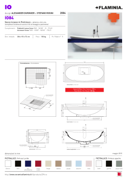
FLOOR FLOOR 830 - (81300) FLOOR 824 - (81324) Operatore oleodinamico interrato ISTRUZIONI PER L’INSTALLAZIONE Underground hydraulic operator INSTRUCTIONS FOR INSTALLATION I UK FLOOR 2 I • Questo prodotto è stato collaudato in GI.BI.DI. verificando la perfetta corrispondenza delle caratteristiche alle direttive vigenti. • La GI.BI.DI. S.r.l. si riserva la facoltà di modificare i dati tecnici senza avviso, in funzione dell'evoluzione del prodotto. LEGGERE ATTENTAMENTE QUESTO MANUALE PRIMA DI PROCEDERE ALL’INSTALLAZIONE. FLOOR 3 I PREMESSA L'operatore FLOOR permette di automatizzare, in modo praticamente invisibile, cancelli ad ante battenti. L'automazione è composta da un operatore interrato, che trasmette il movimento all'anta, e da una centralina oleodinamica di distribuzione integrata nell'operatore. Gli operatori FLOOR 830-824 sono intercambiabili con le versioni FLOOR 810-812, rifarsi al capitolo 18 “Installazione operatore FLOOR 830-824 in una cassetta FLOOR preesistente”. AVVERTENZE PER L’INSTALLAZIONE • Prima di procedere con l'installazione bisogna predisporre a monte dell'impianto un interruttore magnetotermico e differenziale con portata massima 10A. L'interruttore deve garantire una separazione omnipolare dei contatti, con distanza di apertura di almeno 3mm. • Tutti i materiali presenti nell'imballo non devono essere lasciati alla portata dei bambini in quanto potenziali fonti di pericolo. • Il costruttore declina ogni responsabilità ai fini del corretto funzionamento dell'automazione nel caso non vengano utilizzati i componenti e gli accessori di propria produzione e idonei per l'applicazione prevista. • Al termine dell'installazione verificare sempre con attenzione il corretto funzionamento dell'impianto e dei dispositivi utilizzati. • Questo manuale d'istruzione si rivolge a persone abilitate all'installazione di “apparecchi sotto tensione” pertanto si richiede una buona conoscenza della tecnica, esercitata come professione e nel rispetto delle norme vigenti. • La manutenzione deve essere eseguita da personale qualificato. • Prima di eseguire qualsiasi operazione di pulizia o di manutenzione, scollegare l'apparecchiatura dalle rete di alimentazione elettrica. • Questo prodotto e stato progettato e costruito esclusivamente per I'utilizzo indicato in questa documentazione. Usi non indicati in questa documentazione potrebbero essere fonte di danni al prodotto e fonte di pericolo. • Verificare lo scopo dell'utilizzo finale e assicurarsi di prendere tutte le sicurezze necessarie. • L'utilizzo dei prodotti e la loro destinazione ad usi diversi da quelli previsti, non è stata sperimentata dal costruttore, pertanto i lavori eseguiti sono sotto la completa responsabilità dell'installatore. • Segnalare l'automazione con targhe di avvertenza che devono essere visibili. • Avvisare l'utente che i bambini o animali non devono giocare o sostare nei pressi del cancello. • Proteggere adeguatamente i punti di pericolo per esempio mediante l'uso di una costa sensibile. • Verificare se I 'impianto di terra è realizzato correttamente: collegare tutte le parti metalliche della chiusura (porte, cancelli, ecc.) e tutti i componenti dell'impianto provvisti di morsetto di terra. • Usare esclusivamente parti originali per qualsiasi manutenzione o riparazione. • Non eseguire alcuna modifica ai componenti dell'automazione se non espressamente autorizzata dalla Ditta. • Utilizzare materiali adeguati ad assicurare la corretta connessione meccanica del cablaggio e tali da mantenere il grado di protezione IP 67. FLOOR 4 I AVVERTENZE PER L’UTENTE In caso di guasto o anomalie di funzionamento staccare l'alimentazione a monte dell'apparecchiatura e chiamare l'assistenza tecnica. Verificare periodicamente il funzionamento dei dispositivi di sicurezza. Le eventuali riparazioni devono essere eseguite da personale specializzato usando materiali originali e certificati. Il prodotto non deve essere usato da bambini o persone con ridotte capacità fisiche, sensoriali o mentali, oppure mancanti di esperienza e conoscenza. Non accedere alla scheda per regolazioni e/o manutenzioni. ATTENZIONE: IMPORTANTI ISTRUZIONI DI SICUREZZA E' importante per la sicurezza delle persone seguire queste istruzioni. Conservare il presente libretto di istruzioni. 1 - PREDISPOSIZIONI ELETTRICHE Predisporre l'impianto elettrico come indicato [1] facendo riferimento alle norme vigenti per gli impianti elettrici ed altre norme nazionali. Tenere nettamente separati i collegamenti di alimentazione di rete dai collegamenti di servizio (fotocellule, coste sensibili, dispositivi di comando ecc.). I componenti principali dell'automazione sono: À Segnalatore a luce lampeggiante: cavo a 2 conduttori da 0,75 mm² (2x0,75). Á Antenna: cavo coassiale schermato.  Selettore a chiave: cavo a 3 conduttori da 0,5 mm² (3x0,5). à Ricevitore fotocellula: cavo a 4 conduttori da 0,5 mm² (4x0,5). Ä Trasmettitore fotocellula: cavo a 2 conduttori da 0,5 mm² (2x0,5). Å Interruttore magnetotermico-differenziale omnipolare con apertura minima dei contatti pari a 3 mm. Linea di alimentazione all'apparecchiatura 220-230Vac 50-60Hz: cavo a 3 conduttori da 1,5 mm² min. (3x1,5) (attenersi alle norme vigenti). Æ Contenitore apparecchiatura elettronica: cavo 3x1,5 mm². Ç Operatore 230Vac: Alimentazione: cavo a 4 conduttori da 1,5 mm² cadauno: Grigio = comune motore; Marrone = apertura; Nero = chiusura; Giallo/verde = terra Operatore 24Vdc: Alimentazione: cavo a 2 conduttori da 2,5 mm² cadauno per una lunghezza cavo massimo 6 m, oltre è necessario aumentare la sezione del cavo: Rosso = positivo; Nero = negativo Optional Finecorsa: Cavo a 4 conduttori da 0,5 mm². È Bordo sensibile con resistenza 8K2 integrata: cavo a 2 conduttori da 0,5 mm² (2x0,5). É Elettroserratura: cavo a 2 conduttori da 1,5 mm² (2x1,5). É Battute di arresto in apertura e chiusura. FLOOR 5 I Per la posa dei cavi utilizzare adeguati tubi di passaggio. E' buona norma separare i cavi di alimentazione dai cavi di collegamento accessori pertanto è consigliabile la posa di almeno due tubi di passaggio cavi. ATTENZIONE: È importante che sulla linea di alimentazione venga installato, a monte dell'apparecchiatura, un interruttore magnetotermico-differenziale omnipolare con apertura minima dei contatti pari a 3 mm. 2 - DATI TECNICI OPERATORE Frequenza di utilizzo (%Fu) a 20°C Motore elettrico Potenza assorbita Condensatore Grado di protezione Coppia massima Coppia nominale Regolazione della coppia Regolazione della velocità Velocità di rotazione dell’anta Angolo di rotazione Olio idraulico Temperatura di esercizio Protezione termica Finecorsa Lunghezza massima anta Peso massimo anta Tempo di apertura a 90° Blocco idraulico garantito per ante di lunghezza massima Quota minima fra pilastro e asse di rotazione Peso operatore Formula per il calcolo della frequenza di utilizzo FLOOR 824 FLOOR 830 80% [2a] 40% [2b] 24 Vdc 1500 rpm 230 Vac 1450 rpm max 120 W max 190 W – 10 μF IP 67 300 Nm 220 Nm oleodinamica si 7°/s 180° SHELL APR HC13 -20°C +60°C – 100°C optional 3 m [2c] 600 Kg [2c] 13 s 2,0 m 55 mm 15 Kg (come venduto) %Fu = A+C x 100 A+C+P A = Tempo di apertura C = Tempo di chiusura P = Tempo di pausa globale A+C+P = Tempo che intercorre fra due aperture FLOOR 6 I Curva di massimo utilizzo Dai grafici [2a] e [2b] è possibile ricavare il tempo di funzionamento in base alla frequenza di utilizzo desiderata. Diagramma applicativo Dal grafico [2c] è possibile determinare la massima lunghezza dell'anta in base al peso della stessa. 3 - DIMENSIONI Riferimenti ad immagine [3]. 4 - NOMENCLATURA CASSETTA DI FONDAZIONE Riferimenti ad immagine [4]. À Perno autoportante Ø70 mm. Á Prigionieri per il fissaggio dell’operatore.  Fori fissaggio coperchio. à Fori Ø40 mm per il passaggio del cavo elettrico di alimentazione del motore e cavo finecorsa. Ä Foro Ø60 mm di drenaggio per evitare ristagni di acqua. Å Viti fissaggio coperchio. Æ Tappo di accesso allo sblocco manuale. Ç Coperchio cassetta. 5 - NOMENCLATURA OPERATORE FLOOR Riferimenti ad immagine [5]. À Manicotto scanalato orientabile per la trasmissione del moto. Á Asole fissaggio operatore all'interno della cassetta.  Piastra supporto operatore. Ã Ä Cursori di regolazione velocità. Å Cursori di sblocco. Æ Ç Valvola di regolazione coppia espressa. È É Cursori per selezione reversibilità. FLOOR 7 I 6 - AVVERTENZE PRELIMINARI • Verificare che la struttura del cancello sia adeguata per accogliere l'operatore. • Verificare che le parti fisse e mobili del cancello siano strutturalmente integre ed adeguate o se richiedono opere di rinforzo. • Verificare che le parti soggette ad attriti, in particolare la cerniera superiore, non richiedano opere di messa a punto. • Nel campo di azione dell'operatore non devono essere presenti ostacoli di qualsiasi genere. • La posa della cassetta di fondazione deve avvenire in una zona di terreno libera da cavi e tubature e di caratteristiche tali da garantire una adeguata tenuta. • Verificare l'esistenza di una efficiente presa di terra. • Eseguire l'installazione sufficientemente lontano dalla strada in modo da non costituire pericolo per la circolazione. • E' buona norma segnalare l'ingresso automatizzato con targhe di avvertenza di facile visibilità (dentro e fuori) e se il caso, che avvertano i pedoni del divieto di passaggio. • In caso di incertezze sulla sicurezza dell'installazione, sospendere il lavoro e contattare il rivenditore. • Controllare che la struttura del cancello sia sufficientemente robusta. In ogni caso l'attuatore deve spingere l'anta in un punto rinforzato. • Controllare che le ante si muovano manualmente e senza sforzo per tutta la corsa. • Controllare che siano installate le battute di arresto delle ante in apertura e chiusura. • Se il cancello non è di nuova installazione, controllare lo stato di usura di tutti i componenti, sistemare o sostituire le parti difettose o usurate. • L'affidabilità e la sicurezza dell'automazione sono direttamente influenzate dallo stato della struttura del cancello. 7 - DEFINIZIONE ANTA SINISTRA-DESTRA ED INSTALLAZIONE SULLA MEZZERIA INTERNA L’attuatore può essere destro o sinistro e per convenzione si osserva il cancello dal lato interno (verso di apertura) [7a]. L'installazione della cassetta di fondazione può essere eseguita sulla mezzeria del varco (installazione classica) [7b] oppure all'interno del varco [7c]. [7b] [7c]. E' necessario predisporre le battute di arresto a terra À FLOOR 8 I 8 - MURATURA CASSETTA DI FONDAZIONE 1 - Eseguire uno scavo nel terreno sottostante al pilastro [8a], creare una base di ciottolo di ghiaia per evitare [8a]. ristagni di acqua Á [8a]. 2 - La cerniera inferiore preesistente non serve e va rimossa À 3 - Con l'uso di distanziali disporre la cassetta all'interno dello scavo a livello ed in bolla prestando attenzione che il perno presente sulla cassetta sia in asse con la cerniera superiore dell'anta [8b]. [8b] e il tubo Ø60 mm per il 4 - Accertarsi di avere predisposto correttamente i tubi di passaggio cavi Á [8b]. drenaggio delle acque À 5 - Estrarre la cassetta dallo scavo ed eseguire la prima colata di calcestruzzo per creare il fondo. 6 - Accertarsi di avere ostruito tutti i fori presenti sulla cassetta o il calcestruzzo entrerà dentro la cassetta. 7 - Reinserire la cassetta all'interno dello scavo, assicurarsi che la cassetta sia ancora a livello ed in bolla. 8 - Eseguire la seconda colata di calcestruzzo per riempire le intercapedini fra cassetta e scavo. 9 - Attendere che il calcestruzzo faccia presa. 9 - INSTALLAZIONE ANTA L’operatore FLOOR non deve essere presente all'interno della cassetta di fondazione fino a completa installazione dell'anta, in particolare fino a che non siano state eseguite tutte le saldature. Il montaggio del cancello può essere eseguito in due modi: MODO 1 [9a] dalla cassetta, lubrificarlo con grasso e reinserirlo. • Estrarre il perno autoportante  [9a] presente sul perno autoportante  [9a] e la tacca Á [9a] presente sulla • Mettere in fase la tacca À cassetta di fondazione. [9a]. • Appoggiare il cancello direttamente sul perno autoportante  [9a] • Posizionare l'anta in posizione di chiusura verificando che l'allineamento fra tacca su perno autoportante À [9a] sia mantenuto. e tacca su cassetta Á • Verificare che l'anta sia in bolla e che la cerniera superiore dell'anta sia in asse col perno autoportante. • Saldare l'anta sul perno, evitare di usare la cassetta come massa per la saldatrice, perché la corrente di saldatura passerebbe attraverso la bronzina presente sulla cassetta deteriorandone le caratteristiche [9b]. MODO 2 • Procurarsi un profilo ad U (non fornito) di opportune dimensioni [9c]. [9a] dalla cassetta di fondazione. • Estrarre il perno autoportante  • Individuare sul profilo ad U la zona di fissaggio ideale del perno autoportante [9d]. FLOOR 9 I • Saldare il perno autoportante sul profilo ad U facendo in modo che l'estremità fresata sia perpendicolare al profilo ad U [9e]. • Lubrificare con grasso il pignone autoportante. • Inserire nella cassetta il perno autoportante col profilo ad U saldato. • Posizionare l'anta sul profilo ad U. • Assicurarsi che l'anta sia in bolla. [9f] per bloccare l'anta. • Saldare nel profilo ad U una piastrina di opportune dimensioni À 10 - INSTALLAZIONE OPERATORE In caso di sostituzione dell'operatore e se la cassetta di fondazione è stata installata precedentemente al 2011, prestare attenzione a quanto scritto nel capitolo 18. • Muovere l'anta nel verso di apertura per circa 90º. • Sbloccare l'operatore (vedi capitolo 11 “Manovra Manuale”). [10a] nella fresatura presente sul manicotto • Inserire una chiave o altro attrezzo di adeguate dimensioni À [10a]. scanalato Á [10a] nel verso di chiusura fino a che si arriva alla massima corsa • Ruotare il manicotto scanalato Á disponibile. [10a] nel verso di apertura per circa 100º. • Ruotare il manicotto scanalato Á [10a] e reinserirlo con la fresatura allineata come in Á [10b]. • Estrarre il manicotto scanalato Á • Inserire l'operatore nella cassetta di fondazione [10b]. • La fresatura sul perno autoportante e la fresatura sul manicotto scanalato dovrebbero essere allineate [10b] in modo tale da consentire il completo inserimento dell'operatore, se l'operatore non entra facilmente bisogna agire sull'anta, ruotandola leggermente, per creare un allineamento migliore. [10b]. • Fissare l'operatore con i dadi  11 - MANOVRA MANUALE (SBLOCCO) [11a] presente sul coperchio della cassetta di fondazione con l'uso della chiave di sblocco • Svitare il tappo À [11a] sulla quale è presente una fresatura a cacciavite  [11a]. in dotazione Á [5]. • Una volta tolto il tappo [11b] si ha accesso al cursore Å [5]. • Inserire la chiave esagonale di sblocco in dotazione nella sede esagonale presente sul cursore Å • Girare la chiave in senso antiorario per almeno mezzo giro senza sforzare [11c]. [5] arriva bene in • Per il ripristino in automatico ruotare la chiave in senso orario fino quando il cursore Å battuta [11d]. FLOOR 10 I 12 - REGOLAZIONE DELLA COPPIA ESPRESSA [5]; Per aumentare la coppia espressa, ruotare con l'ausilio di un cacciavite, in senso orario le valvole Æ eÇ per diminuire la coppia espressa ruotare le valvole in senso antiorario. In dettaglio sull'operatore installato sull'anta SINISTRA: [5] regola la coppia di CHIUSURA. • La valvola Æ [5] regola la coppia di APERTURA. • La valvola Ç In dettaglio sull'operatore installato sull'anta DESTRA: [5] regola la coppia di APERTURA. • La valvola Æ [5] regola la coppia di CHIUSURA. • La valvola Ç ATTENZIONE: Nell'eseguire l'operazione di regolazione della coppia, ruotare le valvole per gradi dolcemente senza svitarle o avvitarle completamente, tenendo presente che gli operatori vengono forniti con la forza già regolata in modo ottimale in fase di collaudo. L'operatore ha in dotazione le etichette regolazioni pressione per la versione destra e sinistra da applicare sulla centralina. 13 - REGOLAZIONE DELLA VELOCITÀ [11], agire sui cursori à [5]: ruotandoli in senso orario la Utilizzando la chiave per la manovra manuale À eÄ velocità di rotazione del cancello diminuisce; in senso antiorario aumenta. In dettaglio sull'operatore installato sull'anta SINISTRA: [5] regola la velocità in APERTURA. • La valvola à [5] regola la velocità in CHIUSURA. • La valvola Ä In dettaglio sull'operatore installato sull'anta DESTRA: [5] regola la velocità in CHIUSURA. • La valvola à [5] regola la velocità in APERTURA. • La valvola Ä ATTENZIONE: [5] sono influenzate dalla temperatura ambientale. Le velocità ottenibili agendo sulle valvole à eÄ Regolazioni molto basse della velocità associate all'arrivo di temperature basse possono provocare la mancata apertura/chiusura dell'anta. 14 - CONVERSIONE OPERATORE IRREVERSIBILE-REVERSIBILE L'operatore FLOOR viene prodotto e venduto come IRREVERSIBILE, all'occorrenza è possibile renderlo reversibile in apertura o in chiusura oppure sia in apertura che in chiusura. [5], ruotandoli in senso orario fino al completo La reversibilità dell'operatore è regolata dai cursori È eÉ serraggio l'operatore è irreversibile, ruotandoli in senso antiorario fino a portare la testa del cursore a filo con la testata di alluminio, l'operatore diventa reversibile. FLOOR 11 I In dettaglio sull'operatore installato sull'anta SINISTRA: [5] controlla la reversibilità in APERTURA. • La valvola È [5] controlla la reversibilità in CHIUSURA. • La valvola É In dettaglio sull'operatore installato sull'anta DESTRA: [5] controlla la reversibilità in CHIUSURA. • La valvola È [5] controlla la reversibilità in APERTURA. • La valvola É 15 - MONTAGGIO ELETTROSERRATURA Riferimenti ad immagini [15a] e [15b]. L'Elettroserratura è obbligatoria per ante superiori a 2,0 m. À Elettroserratura. Á Piastra di fissaggio elettroserratura.  Aggancio chiavistello. à Battuta per aggancio chiavistello. Ä Chiavistello. Å Barilotto passante (a richiesta). Æ Cancello. 16 - OPTIONAL GRUPPO FINECORSA Sull'operatore FLOOR è possibile installare il kit finecorsa con sensore ad effetto Hall. Il kit finecorsa consente, se utilizzato con idonea apparecchiatura di comando, un migliore e più preciso controllo del movimento dell'anta; i benefici maggiori si ottengono con l'operatore FLOOR a 24Vdc. Il kit è costituito da: • Sensore ad effetto Hall À [16a] che va fissato sul corpo operatore con due viti Á [16a]. • Un disco in lamiera  [16a] che va fissato sotto al manicotto scanalato à [16a] con due viti Ä [16a]. • Due porta magneti in plastica Å [16a], uno di colore nero ed uno di colore bianco, che sono fissati sul disco in lamiera con due viti ciascuno Æ [16a] e sul quale, allentando le viti di fissaggio, saranno liberi di scorrere. Su ogni porta magnete sono premontati due magneti orientati nello stesso senso di polarizzazione, sul porta magneti nero sono premontati due magneti che controllano la chiusura, sul porta magnete bianco sono premontati due magneti che controllano l'apertura [16b]. Lo schema di collegamento del sensore è in Fig. [16c]. Utilizzando centrali Gi.Bi.Di. opportunamente predisposte, il primo magnete che passa sul sensore ad effetto Hall determina l'inizio del moto in rallentamento ed il secondo magnete determina la fine del moto in rallentamento. Rifarsi alle istruzioni della centrale di comando. FLOOR 12 I 17 - VERIFICHE FINALI Alimentare l'automazione: • Se presenti, verificare la corretta lettura dei finecorsa (optional), muovendo manualmente l'anta. Eseguire uno o più cicli completi di apertura e chiusura verificando: • • • • Il corretto funzionamento dei dispositivi di sicurezza; Il movimento regolare delle ante; La solidità della piastra di fondazione; Che il cancello motorizzato sia conforme ai requisiti essenziali di sicurezza richiesti dalla direttiva macchine (2006/42/CE) Per maggiori dettagli e informazioni sulle normative di riferimento potete collegarvi al sito internet: www.gibidi.com 18 - INSTALLAZIONE OPERATORE FLOOR 830-824 IN UNA CASSETTA FLOOR PREESISTENTE In caso si debba procedere alla installazione dell'operatore all'interno di una cassetta preesistente è necessario [18]. verificare che la cassetta abbia il montante di supporto dell'anta sagomato come in À [18] sarà necessario crearli con l'utilizzo di strumenti idonei Se la cassetta non presenta gli alleggerimenti in À (flessibile), sulla zona lavorata sarà necessario applicare un rivestimento protettivo per evitare ossidazioni (zinco spray). 19 - MANUTENZIONE Effettuare controlli periodici al cancello con particolare attenzione a: • • • • Verificare i cardini; Verificare il buon funzionamento dei dispositivi di sicurezza; Sbloccare l'operatore e verificare l'assenza di punti di attrito durante l'intera corsa; Verificare lo stato della boccola autolubrificante. Verificare periodicamente il corretto funzionamento delle sicurezze antischiacciamento e l'efficienza dei sistema di sblocco che permette il funzionamento manuale (vedi paragrafo relativo). I dispositivi di sicurezza installati sull'impianto devono essere verificati ogni sei mesi. Gi.Bi.Di. S.r.l. si riserva la facoltà di modificare i dati tecnici senza avviso, in funzione dell'evoluzione del prodotto. 20 - MALFUNZIONAMENTO Per qualsiasi anomalia di funzionamento non risolta, togliere I'alimentazione al sistema e chiedere I'intervento di personale qualificato (installatore). Nel periodo di fuori servizio, attivare lo sblocco manuale per consentire l'apertura e la chiusura manuale. FLOOR 13 I Dichiarazione di conformità CE Il fabbricante: GI.BI.DI. S.r.l. Via Abetone Brennero, 177/B, 46025 Poggio Rusco (MN) ITALY dichiara che i prodotti: OPERATORE OLEODINAMICO FLOOR 824-830 sono conformi alle seguenti Direttive CEE: • Direttiva EMC 2004/108/CE e successive modifiche; • Direttiva LVD 2006/95/CE e successive modifiche (FLOOR 830) e che sono state applicate le seguenti norme armonizzate: • EN60335-1; EN61000-6-1; EN61000-6-3 Data 10/03/2011 Ammistratore Delegato Oliviero Arosio FLOOR 14 UK • This product has been tested in Gi.Bi.Di. verifying the perfect correspondence of the characteristics to the current directive. • Gi.Bi.Di. S.r.l. reserves the right to modify the technical data without prior notice depending on the product development. PLEASE READ CAREFULLY THIS MANUAL BEFORE PROCEEDING WITH THE INSTALLATION. FLOOR 15 UK INTRODUCTION FLOOR allows practically invisible automation of swing gates. The automated device consists of an hydraulic underground operator, which transfers the movement to the leaf, and of an hydraulic control unit integrated within the operator. FLOOR 830-824 are fully interchangeable with older models FLOOR 810-812; please refer to paragraph 18 “FLOOR 830-824 installation within older FLOOR 810-812 foundation box” for more informations. INSTALLATION WARNINGS • Before proceeding with installation, fit a magnetothermal/differential switch with a maximum capacity of 10A upstream of the system. The switch must guarantee omnipolar separation of the contacts with an opening distance of at least 3mm. • Keep all the materials contained in the packaging away from children since they pose a potential risk. • The manufacturer declines all responsibility for improper functioning of the automated device if the original components and accessories suitable for the specific application are not used. • After installation, always carefully check proper functioning of the system and the devices used. • This instruction manual addresses professionals qualified to install “powered equipment” and therefore requires good technical knowledge and installation in compliance with the regulations in force. • Maintenance must be carried out by qualified personnel. • Before carrying out any cleaning or maintenance operation, disconnect the control unit from the main line. • This product has been designed and constructed exclusively for the use indicated in this documentation. Any other use may cause damage to the product and be a source of danger. • Verify the end purpose of the product and take all the necessary safety precautions. • Use of the products for purposes different from the intended use has not been tested by the manufacturer and is therefore on full responsibility of the installer. • Mark the automated device with visible warning plates. • Warn the user that children or animals should not play or stand near the gate. • Appropriately protect the dangerous points (for example, using a sensitive edge). • Check proper installation of the earthing system: connect all the metal parts of doors, gates, etc. and all the system components to an earth terminal. • Exclusively use original spare parts for any maintenance or repair operations. • Do not modify any components of the automated device unless expressly authorised by Gi.Bi.Di. • Use suitable cable clamps to ensure that the wiring is properly connected mechanically and such that an IP 67 protection degree is maintained. FLOOR 16 UK WARNINGS FOR THE USER In the event of an operating fault or failure, cut the power upstream of the control unit and call Technical Service. Periodically check good functioning of the safety devices. Any repairs must be carried out by specialised personnel using original and certified materials. The product may not be used by children or persons with reduced physical, sensorial or mental capacities or without experience and knowledge. Do not access the board for adjustments and/or maintenance. WARNING: IMPORTANT SAFETY INSTRUCTIONS It is important to follow these instructions to safeguard persons. Keep this instruction booklet. 1 - ELECTRICAL LAYOUT Set up the electric system as shown in Fig. [1] referring to the electric system regulations and other national regulations in force. Keep the mains power connections clearly separated from the service connections (photocells, sensitive edge, control devices, etc.). The main components of the automated device are: À Flashing light: 0.75 mm² 2-core (2x0.75) cable. Á Antenna: screened coaxial cable.  Key selector: 0.5 mm² 3-core (3x0.5) cable. à Photocell receiver: 0.5 mm² 4-core (4x0.5) cable. Ä Photocell transmitter: 0.5 mm² 2-core (2x0.5) cable. Å Omnipolar magnetothermal/differential switch with minimum contact opening of 3 mm. 220-230VAC/50-60 Hz power line to the device: 1.5 mm² 3-core cable (3x1.5) (adhere to the regulations in force). Æ Case for electronic control unit: 3x1.5 mm² cable. Ç 230Vac operator: Power: 1.5 mm² 4-core (4x1.5) cable: Grey = common motor; Brown = opening; Black = closing; Yellow/green = earth 24Vdc operator: Power: 2.5 mm² 2-core (2x2.5) cable, for a maximum cable length of 6 m, beyond which the cable crosssection needs to be increased: Red = positive; Black = negative Optional Limit Switch: 0.5 mm² 4-core (4x0.5) cable. È 8K2 sensitive edge: 0.5 mm² 2-core (2x0.5) cable. É Electronic lock; 1.5 mm² 2-core (2x1.5) cable. É Mechanical stop in opening and closing FLOOR 17 UK Use appropriate cable ducts. It is good practice to separate the power cables from the accessory connection cables and it is therefore advisable to use at least two tubes to run the cables through. WARNING: It is important to fit an omnipolar magnetothermal/differential switch with a minimum contact opening of 3 mm on the power line upstream of the control unit. 2 - TECHNICAL DATA OPERATOR Operating frequency (%Fu) at 20°C Electric motor Power absorbed Motor capacitor Protection degree Maximum torque Nominal torque Torque regulation Speed regulation Leaf rotation speed Leaf rotation angle Hydraulic oil Operating temperature Thermal protection Limit switch Leaf maximum lenght Leaf maximum weight Opening time to 90° Hydraulic lock granted for maximum lenght leaf Minimum between pillar and axis of rotation Operator weight Formula to calculate the operating frequency FLOOR 824 FLOOR 830 80% [2a] 40% [2b] 24 Vdc 1500 rpm 230 Vac 1450 rpm max 120 W max 190 W – 10 μF IP 67 300 Nm 220 Nm hydraulic yes 7°/s 180° SHELL APR HC13 -20°C +60°C – 100°C optional 3 m [2c] 600 Kg [2c] 13 s 2.0 m 55 mm 15 Kg (as sold) %Fu = A+C x 100 A+C+P A = Opening time C = Closing time P = Overall pause time A+C+P = Time between two openings FLOOR 18 UK Maximum operating curve The operating time based on the desired operating frequency can be derived from the graphs in Fig. [2a] and [2b]. Application diagram The maximum leaf lenght related to the weight can be derived from the graph in Figure [2c]. 3 - DIMENSIONS Refer to figure [3]. 4 - FOUNDATION BOX DESCRIPTION Refer to figure [4]. À Self-supporting pin Ø70 mm. Á Stud for fixing operator.  Cover fixation holes. à Holes Ø40 mm for motor and limit switches wires. Ä Hole Ø60 mm for water draining. Å Cover fixation screws. Æ Protective cap for manual unlocking. Ç Foundation box cover. 5 - FLOOR OPERATOR DESCRIPTION Refer to figure [5]. À Adjustable splined sleeve for motion transmission. Á Operator fixing slot.  Operator support plate. Ã Ä Speed regulation cursors. Å Unlocking cursors. Æ Ç Torque regulation valves. È É Cursors for reversibility selection. FLOOR 19 UK 6 - PRELIMINARY WARNINGS • Check that the gate structure is adapted for installing the operator. • Check for the fixed and mobile parts of the gate to be structurally intact and appropriate or whether require reinforcement work. • Check that the parts subject to friction, especially the top hinge, does not require any setup. • In the working area there must be no obstacles of any kind. • The foundation box must be laid in an area free from cables and pipes and such as to ensure a proper seal. • Check the existence of an efficient earth. • The installation should be done far away from any road, so as not to pose a threat to circulation. • It is useful to signal the automatic entrance with warning plates of easy visibility (inside and outside) and, if necessary, that warn pedestrians they are not allowed to pass through. • If the installation presents some un-safety details, stop the work and contact your dealer. • Check that the gate structure is strong enough. In any case the operator must push the gate at a reinforced point. • Check that the leaves can be moved manually without effort throughout the stroke. • Check that the mechanical stop, both in opening and closing are correctly installed. • If the automatic system is not a completely new installation, check the wear of all components and repair or replace defective or worn parts. • Reliability and safety are directly affected by the condition of the gate structure. 7 - DEFINITION OF LEFT-RIGHT WING AND MIDDLE INSTALLATION The operator can be left or right and by convention is looking from the inside (opening direction) [7a]. The installation of the foundation box can be done on the center line of the passage (classic installation) [7b] or in the passageway [7c]. [7b] [7c]. It is necessary to provide the mechanical stop À FLOOR 20 UK 8 - FOUNDATION BOX LAYING 1 - Make a hole in the ground underneath the pillar [8a] and create a base of pebble gravel to avoid backwater [8a]. Á [8a]. 2 - The existing bottom hinge is no more useful and must be removed À 3 - By means of spacers put the foundation box inside the hole, using the spirit level to ensure the correct installation and paying attention that the pin on the box is aligned with the top hinge of the gate [8b]. [8b] and the Ø60 mm drain pipe À [8b]. 4 - Make sure you have properly prepared the cable duct Á 5 - Remove the box from the excavation and run the first concrete layer to create the basement. 6 - Make sure you have blocked all the holes on the foundation box or the concrete will enter within the box itself. 7 - Put the box on the site, make sure the box is still wide and level. 8 - Run the second concrete layer to fill in the spaces between the box and the digging. 9 - Wait for the concrete to set. 9 - LEAF INSTALLATION The FLOOR operator must not be present within the foundation box until the leaf installation is completed, especially until all welds have been done. The installation of the gate can be done in 2 different ways: MODE 1 [9a] from the foundation box, lubricate with grease and insert again. • Remove the self-supporting pin  [9a] of the self-supporting pin  [9a] with the notch Á [9a] on the foundation box. • Phase the notch À [9a]. • Place the gate directly on the self-supporting pin  [9a] and box Á [9a] are still • Place the gate in closed position making sure that the notches on pin À aligned. • Make sure the leaf is level and that the top hinge is aligned with the pin. • Weld the leaf on the pin, avoiding to use the box as ground for welding, because the welding current would pass through the bushing causing damage to the bushing itself [9b]. MODE 2 • Take a U profile (not included) of right size [9c]. [9a] from the foundation box. • Remove the self-supporting pin  • On the U profile find the correct position for the fixation of the pin [9d]. FLOOR 21 UK • Weld the pin on the U profile by ensuring the milled end is perpendicular to the U section [9e]. • Lubricate with grease the self supporting pinion. • Put within the box the pin with the U profile welded. • Place the leaf on the U profile. • Make sure the leaf is level. [9f] to block the leaf. • On the U profile weld a plate of right size À 10 - OPERATOR INSTALLATION If you need to change the operator and the foundation box has been laid before the year 2011, please refer to paragraph 18. • Move the leaf toward opening for about 90º. • Unlock the operator (see chapter 11 “Manual Unlocking Operation”). [10a] into the splined sleeve milling Á [10a]. • Insert a spanner or other tool À [10a] towards closing until it reaches the maximum stroke available. • Turn round the splined sleeve Á [10a] towards opening for about 100º. • Turn round the splined sleeve Á [10a] and then insert again with the milling aligned as in Á [10b]. • Remove the splined sleeve Á • Insert the operator within the foundation box [10b]. • The millings on the self-supporting pin and on the splined sleeve should be aligned [10b] so as to allow the installation of the operator; if the operator does not fit you should move the leaf, turning round a little bit, until it reaches the correct alignment. [10b]. • Fix the operator with nuts  11 - MANUAL UNLOCKING OPERATION [11a] on the cover of the foundation box by means of the included unlocking key • Unscrew the cap À [11a]. Á [5]. • Once removed the cap [11b] you can access the unlocking cursor Å [5]. • Insert the hexagon wrench into the hexagon seat of the cursor Å • Turn anti-clockwise the key for about half rotation without effort [11c]. [5] reaches its own stop [11d]. • To restore automatically functioning turn clockwise the key until the cursor Å FLOOR 22 UK 12 - TORQUE REGULATION [5]; to decrease motor torque turn anti-clockwise To increase motor torque turn clockwise the valves Æ and Ç the valves. In detail with operator installed on LEFT leaf: [5] regulates CLOSING torque. • The valve Æ [5] regulates OPENING torque. • The valve Ç In detail with operator installed on RIGHT leaf: [5] regulates OPENING torque. • The valve Æ [5] regulates CLOSING torque. • The valve Ç WARNING: During torque regulation be aware to turn the valves smoothly and gradually without screwing or unscrewing completely. Please note that all operators are provided with the force already set in its best way during internal testing. The operator is equipped with pressure control labels, both for right and left version, to be applied on the hydraulic control unit. 13 - SPEED REGULATION [11], act on the cursors à [5]: turning clockwise the By using the key for manual unlocking operation À and Ä rotation speed of the gate decreases, turning anti-clockwise it increases. In detail with operator installed on LEFT leaf: [5] regulates speed during OPENING. • The valve à [5] regulates speed during CLOSING. • The valve Ä In detail with operator installed on RIGHT leaf: [5] regulates speed during CLOSING. • The valve à [5] regulates speed during OPENING. • The valve Ä WARNING: [5] are influenced by ambient temperature. The speeds obtained using the valves à and Ä Very low speed regulations together with cold temperature may cause the gate not to open or close. 14 - CONVERSION FROM IRREVERSIBILE TO REVERSIBLE OPERATOR The FLOOR operator is manufactured and provided as IRREVERSIBLE. If you need you can transform it into reversible mode in opening or in closing or both opening and closing. [5]; turning clockwise until they are blocked the operator The reversibility is controlled by the cursors È and É is irreversible; turning anti-clockwise until the top of the cursor is at level with aluminium head the operator becomes reversible. FLOOR 23 UK In detail with operator installed on LEFT leaf: [5] controls reversibility in OPENING. • The valve È [5] controls reversibility in CLOSING. • The valve É In detail with operator installed on RIGHT leaf: [5] controls reversibility in CLOSING. • The valve È [5] controls reversibility in OPENING. • The valve É 15 - ELECTROLOCK INSTALLATION Refers to pictures [15a] and [15b]. The electrolock must be installed on leaves 2.0 meters long or more. À Electrolock. Á Electrolock fixing plate.  Bolt hooker. à Bolt hooking rabbet. Ä Bolt. Å Key cilynder (on request). Æ Gate. 16 - LIMIT SWITCH KIT (OPTIONAL) FLOOR operator is suited to be equipped by limit switch kit with Hall effect sensor. The kit allows you to switch, when used with appropriate electronic control device, a better and more precise control of leaf movement; the more benefits you get with the operator FLOOR 24Vdc. The kit consists of: • Hall-effect sensor À [16a] which is fastened with two screws on the operator housing Á [16a]. • A disk plate  [16a] to be fixed under the sleeve spline à [16a] with two screws Ä [16a]. • Two plastic magnets holders Å [16a], one black and one white, which are fixed on the disk plate with two screws each Æ [16a] and on which, by loosening the screws, they will be free to slide. Each magnet holder is pre-assembled with two magnets oriented in the same sense of polarization: the black one is pre-assembled with two magnets that control the closing, the white one is pre-assembled with two magnets that control the opening [16b]. The wiring diagram of the sensor is in [16c]. Using Gi.Bi.Di. control units properly set, the former magnet passing on the Hall effect sensor starts slow down motion, the latter stops slow down motion. Refer to the instruction manual of the electronic control unit. FLOOR 24 UK 17 - FINAL CHECKS Power the automatic system: • If installed, check for the correct operation of the limit switch manually moving the leaf. Run one or more operation cycles and check: • • • • The correct operation of the safety devices; The correct movement of both the leaves; That the foundation plate is solid; That the automatic gate complies with the essential safety requirements required by the Machinery Directive (2006/4/CE) For more details and informations on European Directives please visit web site: www.gibidi.com 18 - FLOOR 830-824 INSTALLATION WITHIN OLDER FLOOR 810-812 FOUNDATION BOX If you need to install the operator within an existing box you must check that the box has the supporting post of [18]. the leaf shaped like À [18] you must create them using proper tools (flexible), If the foundation box does not have the lightening in À the work area will need to apply a protective coat to avoid oxidation (zinc spray). 19 - MAINTENANCE Carry out periodic checks on the gate with particular attention to: • • • • Check the hinges; Check the correct operation of the safety devices; Unlock the operator and verify there is no friction points during the whole stroke; Check the self-lubricating bushing. Periodically check the correct functioning of anti-crushing safety and the efficiency of the unlocking system which allows the manual operation (see relevant paragraph). The safety devices installed must be checked at least each 6 months. Gi.Bi.Di. S.r.l. reserves the right to modify the technical data without prior notice depending on the product development. 20 - MALFUNCTIONING In the event of any malfunction, cut the power to the system and call in a qualified technician (installer). During out of service activate manual release to allow manual opening and closing. FLOOR 25 UK CE Declaration of conformity The manufacturer: GI.BI.DI. S.r.l. Via Abetone Brennero, 177/B, 46025 Poggio Rusco (MN) ITALY declares that the products: HYDRAULIC OPERATOR FLOOR 824-830 are in conformity with the following EEC Directives: • EMC Directive 2004/108/CE and subsequent amendments; • LVD Directive 2006/95/CE and subsequent amendments (FLOOR 830) and that the following harmonised standards have been applied: • EN60335-1; EN61000-6-1; EN61000-6-3 Date 10/03/2011 Managing Director Oliviero Arosio FLOOR 26 NOTE / NOTES FLOOR NOTE / NOTES 27 Cod. AIC6532 - 03/2011 - Rev. 00 GI.BI.DI. S.r.l. Via Abetone Brennero, 177/B 46025 Poggio Rusco (MN) - ITALY Tel. +39.0386.52.20.11 Fax +39.0386.52.20.31 E-mail: [email protected] Numero Verde: 800.290156 w w w . g i b i d i . c o m
Scaricare