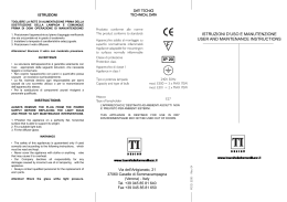
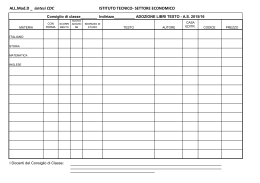
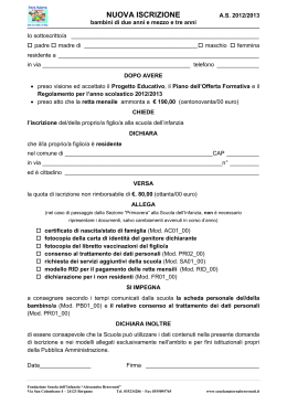
FRIGGITRICI ELETTRICHE
ELEKTRO-FRITEUSE
ELECTRIC-HEATED FRYERS
FRITEUSES ELECTRIQUES
FREIDORAS ELECTRICAS
FRITEUSEN (ELEKTRO)
Mod. FQE-41...
MOD. OFQE-41R
MOD. OFQE-61R
Mod. FQE-61...
MOD.
FE62T10
Mod. FQE-41R...
FE64T10
Mod. FQE-61R...
MOD. OFQE-41 115.104
MOD. OFQE-61 115.105
Mod. FQE-40...
Mod. FQE-60...
Mod. FQE-38...
Mod. FQE-58...
30363-06
AVVERTENZE D’INSTALLAZIONE, DI REGOLAZIONE,
D’IMPIEGO E DI MANUTENZIONE (pagina 2-5)
NOTICES D’INSTALLATION, DE REGLAGE, D’EMPLOI ET
D’ENTRETIEN (page 14-17)
AUFSTELLUNGS-, GEBRAUCHS- UND INSTANDHALTUNGS-ANWEISUNGEN (Seite 6-9)
INSTRUCCIONES DE INSTALACION, REGULACION, USO
Y MANTENIMIENTO (plana 18-21)
INSTRUCTION FOR INSTALLATION, ADJUSTMENT, USE
AND MAINTENANCE (page 10-13)
AANWIJZINGEN VOOR DE INSTALLATIE, DE AFSTELLING,
HE GEBRUIK EN HET ONDERHOUD (pagina 22-25)
APPENDICE - ANHANG - APPENDIX - APPENDICE - APENDICE - AANHANGSEL (26-32)
*
*
*
* * **
*
* * **
Leggere attentamente il libretto e conservarlo con cura per tutta
la durata del prodotto.
Leggere subito le avvertenze!
Lire attentivement le manuel et le conserver avec soin pour toute
la durée du produit.
Lire tout de suite les avertissements!
Die Geräteanweisung aufmerksam lesen und für die ganze
Gerätedauer sorgfältig aufbewahren.
Die Hinweise sollen sofort gelesen werden!
Leer atentamente el manual y conservarlo con atención por toda
la durada del producto.
Leer enseguida las Advertencias!
Read the manual with attention and keep it carefully for the
whole duration of the appliance.
Read the warning remarks immediately!
Lees de handleiding aandachtig en bewaar het zorgvuldig
gedurende de hele levensduur van het apparaat.
Lees de waarschuwingen onmiddellijk!
Doc. No. 30363-06
0506
GB
INDEX
INSTALLATION INSTRUCTIONS ----------------------------------------------------------------------- page
WARNINGS ---------------------------------------------------------------------------------------------------------- page
INSTALLATION ------------------------------------------------------------------------------------------------------ page
Positioning
Assembly
In line union of the appliances
Electrical connection
Earth and unipotential connections
Important information specifically relating to appliances in the DROP-IN series
START-UP ------------------------------------------------------------------------------------------------------------page
Function check
Nominal heat input check
ANALYSIS OF SEVERAL FAILURES --------------------------------------------------------------------------------- page
Heating elements do not heat up
Difficult or lacking temperature adjustment
REPLACEMENT OF PARTS SUBJECT TO CHANGE ----------------------------------------------------------------- page
Temperature regulation thermostat and manually-reset safety thermostat
Well heating elements
USE AND MAINTENANCE ----------------------------------------------------------------------------------page
WARNINGS ----------------------------------------------------------------------------------------------------------- page
Safety devices
USE ------------------------------------------------------------------------------------------------------------------page
Filling of well
Operation
Switching off heating
Oil drainage
CLEANING AND MAINTENANCE ------------------------------------------------------------------------------------ page
LIST OF PARTS SUBJECT TO CHANGE ----------------------------------------------------------------------------- page
--- 11
--- 11
--- 11
--- 11
--- 11
--- 12
--- 12
--- 12
--- 12
--- 13
--- 13
APPENDIX ---------------------------------------------------------------------------------------------------------- page --- 26
10/32
Electric heated fryers 600 series (30363)
INSTALLATION INSTRUCTIONS
appliance installed to the terminals, marked by
the symbol
(unipotential system).
WARNINGS
Installation, adjustments and maintenance of the
appliances must be done by authorized installers,
in accordance with the safety standards in force.
The manufacturer declines any responsibility
if such obligation is not observed.
INSTALLATION
Positioning
– The overall/connection dimensions and the
technical data are stated in the pages in the
appendix.
– Install the appliances only in sufficiently aired
rooms.
– Position appliances at least 10 cm from the
nearby walls. Such distance can be less when
the walls are incombustible or protected by a
thermal insulator.
– The appliances are not suitable for built-in
installation.
Assembly
– Remove the film which protects the external
panels. Any glue remaining on these is to be
removed with a suitable solvent.
In line union of the appliances
– Put the appliances next to eachother and level
them at the same height.
– Unite the appliances using the special union
joint-coverings supplied upon request.
Electrical connections
– The appliances are designed to operate at the
voltage indicated on the rating plate.
– Each appliance must be connected to an
independent mains supply of suitable capacity
(total power indicated in “Technical data” table)
via an input terminal board with flexible rubber
cable, insulated at a level not below H07RN-F.
– Make sure that the cables lenght allows for the
live wires to disconnect from terminal block
before the yellow/green ground wire, in case of
simultaneous pull.
– Automatic cutout omnipolar switches of suitable
capacity (with contacts opening to at least 3
mm) and highly sensitive automatic differential
protective devices must be fitted. These must
ensure that there is no direct or indirect contact
between live components and fault currents
and the ground, in accordance with current
regulations (maximum admissible leakage
current 1 mA/kW).
Earth and unipotential connections
– Appliances must be earthed on terminals
marked with the symbol
.
– Connect the metallic structure of every electrical
Important information specifically relating to
appliances in the DROP-IN series
– The appliance must be installed in strict
compliance with the directions given in the
attached drawings.
– Appliances should only be installed on units
made of metal (and not wood and/or other
flammable materials).
– Take particular care with the power lead: the
channelways must be perfectly smooth with no
sharp corners and/or edges. The lead must not, at
any point, be subjected to temperatures of more
than 50°C above normal room temperature.
START-UP
Function check
– Start-up the appliance following the instructions
given; check function regularity and make sure
that the controls and heating elements are in
good working order, testing them with the
various function positions.
– The appliance is equipped with an internal
safety thermostat for each well, which cuts off
the power supply to the heating elements
whenever the main temperature regulator is
faulty.
– If necessary consult paragraph “Analysis of
several failures”.
Nominal heat input check
– After installation and at each maintenance
intervention check the heat input of the
appliance.
– The nominal heat input is stated in the
“Technical data” table.
– The appliance operates at the nominal heat
input when the electrical power is the one stated
in Table T1.
ATTENTION If the power supply value is not
within the limits indicated in Table T1, interrupt
the operation of the appliance and contact the
electricity delivery body.
ANALYSIS OF SEVERAL FAILURES
Heating elements do not heat up
– Check fuse valves
– Main switch off
– Insufficient power or wrong electrical connection
– Temperature regulation thermostat faulty
– Safety thermostat activated (because the main
temperature regulator is faulty). To reset the
safety thermostat, remove the screw sealing the
thermostat access hole on the control panel.
Reset the thermostat, pressing with a pointed
tool (e.g. slender screwdriver).
Diffcult or lacking temperature adjustment
Electric heated fryers 600 series (30363)
11/32
– Temperature regulation thermostat faulty
– Wrong connection or heating elements faulty
(replace faulty element).
REPLACEMENT OF PARTS SUBJECT TO CHANGE
IMPORTANT Before carrying out repairs, unplug
appliance from mains disconnecting the main
switch.
Sealed components must not be tampered
with.
Temperature regulation thermostat and manuallyreset safety thermostat
– Drain oil from the relevant well, emptying it
completely (see paragraph headed “Oil
drainage”)
– Remove control panel.
– Loosen thermostat bulb to be changed; this is
secured between the heating elements with a
flexible clip.
– Disconnect electrical connections between
thermostat and other devices
– Change component.
Well heating elements
– Drain oil from the relevant well, emptying it
completely (see paragraph headed “Oil
drainage”)
– Remove control panel and cover protecting
harnessing on heating elements.
– Loosen thermostat bulbs which are secured
between the heating elements (to remove them,
loosen screws securing the supporting plates)
– Disconnect heating element.
– Change component.
USE AND MAINTENANCE
flame point from lowering and thereby creating a
fire risk; in this way, the boiling oil is also less
likely to spatter.
Do not fry pieces of food which are large or have not
been drained, as these may cause the oil to spit.
Do not use the well when the oil has dropped below
the minimum level indicated, as this may cause the
oil to catch fire.
Safety devices
Appliances are equipped with following:
– Additional safety thermostat, which
automatically cuts off the electricity supply to
heating elements and stops the heating function
when oil temperature exceeds the maximum
working temperature (operating thermostat
faulty). If this should occur, cut off the electricity
supply to the appliance and contact your nearest
customer service centre.
– Safety oil drainage tap against accidental
openings during work.
USE
Filling well
– Close the drain cock by turning the control lever
to setting
.
– Pour the oil or fat blocks into the frying well and
fill up to the notch indicating the minimum level.
– IMPORTANT: Do not heat up the fryer
unless the well contains oil!
Operation
To switch on heating (pilot lamp on) turn the
temperature regulator knob on the desired working
position.
0
off
60 °C
minimum temperature
WARNINGS
Caution, appliance with hot surfaces!
The appliance is for professional use and must be
used by trained personnel. It is for the cooking of
food. Any other use of the appliance is considered
improper.
IMPORTANT: never start up appliance unless
the well contains oil.
The installation and adaptation to other voltages
(if possible) must be done by qualified and
authorized installers.
In case of breakdown diconnect the main switch.
Sealed components must not be tampered with.
For repairs consult only authorized service centres
and ask for original spare parts only.
The manufacturer declines any responsability
if such obligations are not observed.
Carefully read this booklet and keep it in a safe
place. Before using the appliance carefully clean
all the surfaces that will come in contact with food.
Furthermore..
Used oil must always be changed to prevent the
12/32
Electric heated fryers 600 series (30363)
intermediate temperatures
180 °C
maximum temperature
Switching off heating
– Turn temperature regulator knob on position
“0” (pilot lamp off).
Oil drainage
Important: The container used for well drainage
must be large enough and of heat resistant material.
– Insert the extension hose with the bayonet
safety joint (supplied with fryer unit) into the
drainage outlet on the well.
– Move the control lever on the drain cock to
setting
(pressing the lever down and
pulling it forward).
CLEANING AND MAINTENANCE
– Before any cleaning operation disconnect the
electrical supply (if present).
– It is necessary to avoid rusty water being in
contact with stainless steel surfaces. Therefore
–
–
–
–
–
–
–
before filling wells with water open water tap
and let water flow until it is perfectly clear.
Clean stainless steel surfaces daily with water
and non abrasive common detergents, rinse
well and dry thoroughly.
Do not use iron scouring pads or chlorate
products.
Do not use sharp objects which can scratch and
ruin the steel surface.
Do not use corrosive products to clean the floor
under the appliance.
Do not wash the appliance with water jets.
Before a long period of inactivity disconnect the
main switch. Proceed to its thorough cleaning.
At least twice a year, ask for the intervention of
an authorized technician authorized for checking
the appliance. It is advisable in any case to
stipulate a maintenance contract.
LIST OF PARTS SUBJECT TO REPLACEMENT
–
–
–
–
–
–
–
Heating elements
Safety thermostats
Temperature regulation thermostats
Temperature regulation thermostat knobs
Oil drainage cock
Switch
Contactor
Electric heated fryers 600 series (30363)
13/32
APPENDICE - ANHANG - APPENDIX - APPENDICE - APENDICE - AANHANGSEL
DATI TECNICI - TECHNISCHE DATEN - TECHNICAL DATA
DONNEES TECNIQUES - DATOS TÈCNICOS - TECHNISCHE GEGEVENS
T1.1 (Mod. FQE-41…/61…, OFQE-41.../61...)
Ø
▲ Capacità
● Carico
MAX
MIN
al livello
H 07
MAX
MAX
A
RN-F
mm
l.
kg
MOD.
kW ❍
V
FQE-41,OFQE-41,FQE-41D,FQE-41DB
9
3NAC 400V
13
5 x 1,5
12 ÷ 18
10
1,5
FQE-41L, FQE-41LD, FQE-41LDB
6
3NAC 400V
8,7
5x1
9 ÷ 14
10
1,5
FQE-41L/2
6
3AC 230V
15
4 x 1,5
9 ÷ 14
10
1,5
FQE-61,OFQE-61,FQE-61D,FQE-61DB
18
3NAC 400V
26
5x4
12 ÷ 18
10 + 10
1,5 + 1,5
FQE-61L, FQE-61LD, FQE-61LDB
12
3NAC 400V
17,3
5 x 2,5
12 ÷ 18
10 + 10
1,5 + 1,5
FQE-61L/2
12
3AC 230V
30
4x4
12 ÷ 18
10 + 10
1,5 + 1,5
Ø
▲ Capacità
● Carico
MAX
T1.1 (Mod. FQE-40…/60…)
MIN
al livello
H 07
MAX
MAX
kW ❍
V
A
RN-F
mm
l.
kg
FQE-40, FQE-40D
5,5
3NAC 400V
7,9
5x1
9 ÷ 14
10
1,5
FQE-40D-SP, FQE-38D-SP
7,25
3NAC 400V
10,4
5 x 1,5
9 ÷ 14
10
1,5
11
3NAC 400V
15,9
5 x 1,5
12 ÷ 18
10 + 10
1,5 + 1,5
14,5
3NAC 400V
21
5 x 1,5
12 ÷ 18
10 + 10
1,5 + 1,5
MOD.
FQE-60, FQE-60D
FQE-60D-SP, FQE-58D-SP
❍
Potenza totale - Gesamtleistung - Total power - Puissance totale - Potencia total - Totale capaciteit
▲ Capacità al livello MAX - Fassungsvermögen am Höchststand - MAX Capacity - Capacité MAX - Capacidad MAX - Inhoud op
het MAX. niveau
● Carico MAX - MAX Fassungsvermögen - MAX Storage capacity - Capacité de charge MAX - Carga MAX - MAX. vulling
26/32
Appendice - Anhang - Appendix - Appendice - Apendice - Aanhangsel (30363-05)
APPENDICE - ANHANG - APPENDIX - APPENDICE - APENDICE - AANHANGSEL
DATI TECNICI - TECHNISCHE DATEN - TECHNICAL DATA
DONNEES TECNIQUES - DATOS TÈCNICOS - TECHNISCHE GEGEVENS
T1.1 (Mod. FQE-41R.../61R...OFQE-41R, OFQE-61R)
Ø
▲ Capacità
● Carico
MAX
MIN
al livello
H 07
MAX
MAX
A
RN-F
mm
l.
kg
kW ❍
V
FQE-41R,OFQE-41R,CFE62110/1
9
3NAC 400V
13
5 x 1,5
12 ÷ 18
10,5
1
FQE-41RL,CFE62110
6
3NAC 400V
8,7
5x1
9 ÷ 14
10,5
1
FQE-41RL/2,CFE62110/230
6
3AC 230V
15
4 x 1,5
9 ÷ 14
10,5
1
FQE-61R,OFQE-61R,CFE62210/1
18
3NAC 400V
26
5x4
12 ÷ 18
10,5 + 10,5
2+1
FQE-61RL,CFE62210
12
3NAC 400V
17,3
5 x 2,5
12 ÷ 18
10,5 + 10,5
2+1
FQE-61RL/2,CFE62210/230
12
3AC 230V
30
4x4
12 ÷ 18
10,5 + 10,5
1+1
MOD.
❍
Potenza totale - Gesamtleistung - Total power - Puissance totale - Potencia total - Totale capaciteit
▲ Capacità al livello MAX - Fassungsvermögen am Höchststand - MAX Capacity - Capacité MAX - Capacidad MAX - Inhoud op
het MAX. niveau
● Carico MAX - MAX Fassungsvermögen - MAX Storage capacity - Capacité de charge MAX - Carga MAX - MAX. vulling
Appendice - Anhang - Appendix - Appendice - Apendice - Aanhangsel (30363-05)
27/32
SERIE 600
MOD. FQE-41, FQE-41L, FQE-41L/2
FQE-61, FQE-61L, FQE-61L/2, OFQE-41, OFQE-61
INSTALLATION DIAGRAM
SCHEMA DI INSTALLAZIONE - INSTALLATIONSPLAN
- SCHEMA D’INSTALLATION - ESQUEMA DE INSTALACION - INSTALLATIESCHEMA
(Misure in cm - Abmessungen in cm - Measurements in cm - Mésures en cm - Medida en cm - Maten in cm)
FQE-61
FQE-61L, FQE-61L/2
OFQE-61
46,6
46,6
FQE-41
FQE-41L, FQE-41L/2
OFQE-41
3,6
3,6
P
1,4
6,9
8,4
8,4
40
6,5
60
8,4
5,3
42,5
11
60
8,4
6,9
1,4
1,4
6,9
M
60
60
P M
65.3
P
11,5
3,6
15,5
9
2,5
3,6
P
2,5
9
P
6,9
65.3
M
4
4
M
29,5
M
40
60
Legenda - Legende - Key - Légende - Leyenda - Legenda
M
P
28/32
- Morsettiere di arrivo linea - Netzanschlußklemme - El. power connection blocks - Branchements électriques - Llegadas linea electrica Aansluitingsklemmenstrook
- Pressacavo linea elettrica - Stopfbuchse - Electric cable stress relief - Presse-étoupe de câble él. - Pisacable - Elektrische kabelwartel
Appendice - Anhang - Appendix - Appendice - Apendice - Aanhangsel (30363-05)
SERIE 600
MOD. FQE-41R, FQE-41RL, FQE-41RL/2
MOD. CFE62110/1, CFE62110, CFECFE62110/230
MOD. FQE-61R, FQE-61RL, FQE-61RL/2, OFQE-41R, OFQE-61R
MOD. CFE62210/1, CFE62210, CFE62210/230
INSTALLATION DIAGRAM
SCHEMA DI INSTALLAZIONE - INSTALLATIONSPLAN
- SCHEMA D’INSTALLATION - ESQUEMA DE INSTALACION - INSTALLATIESCHEMA
46,6
46,6
(Misure in cm - Abmessungen in cm - Measurements in cm - Mésures en cm - Medida en cm - Maten in cm)
3,6
15,5
3,6
11,5
9
2,5
3,6
P
2,5
9
P
6,9
3,6
P
1,4
6,9
8,4
8,4
40
6,5
60
8,4
5,3
42,5
11
60
8,4
6,9
1,4
1,4
6,9
60
60
P M
65.3
P M
65.3
M
4
4
M
29,5
M
40
60
Legenda - Legende - Key - Légende - Leyenda - Legenda
M
P
- Morsettiere di arrivo linea - Netzanschlußklemme - El. power connection blocks - Branchements électriques - Llegadas linea electrica Aansluitingsklemmenstrook
- Pressacavo linea elettrica - Stopfbuchse - Electric cable stress relief - Presse-étoupe de câble él. - Pisacable - Elektrische kabelwartel
Appendice - Anhang - Appendix - Appendice - Apendice - Aanhangsel (30363-05)
29/32
SERIE 600
MOD. FQE-40
MOD. FQE-60
INSTALLATION DIAGRAM
SCHEMA DI INSTALLAZIONE - INSTALLATIONSPLAN
- SCHEMA D’INSTALLATION - ESQUEMA DE INSTALACION - INSTALLATIESCHEMA
(Misure in cm - Abmessungen in cm - Measurements in cm - Mésures en cm - Medida en cm - Maten in cm)
FQE-60
M
3,6
15,5
3,6
3,6
P
1,4
6,9
8,4
8,4
6,5
60
40
8,4
5,3
42,5
11
60
8,4
6,9
6,9
1,4
1,4
M
60
60
P M
65.3
P
11,5
4
3,6
6,9
65.3
M
P
2,5
9
P
2,5
9
4
M
29,5
46,6
46,6
FQE-40
40
60
Legenda - Legende - Key - Légende - Leyenda - Legenda
M
P
30/32
- Morsettiere di arrivo linea - Netzanschlußklemme - El. power connection blocks - Branchements électriques - Llegadas linea electrica Aansluitingsklemmenstrook
- Pressacavo linea elettrica - Stopfbuchse - Electric cable stress relief - Presse-étoupe de câble él. - Pisacable - Elektrische kabelwartel
Appendice - Anhang - Appendix - Appendice - Apendice - Aanhangsel (30363-05)
IT
AVVERTENZE PER L'ASSEMBLAGGIO E L'INSTALLAZIONE DROP-IN
MONTAGE-UND EINRICHTUNGSANWEISUNGEN EINBAUGERATE
INSTRUCTIONS FOR ASSEMBLY AND INSTALLATION DROP-IN SYSTEM
INSTRUCTIONS POUR L'ASSEMBLAGE ET L'INSTALLATION DROP-IN
INSTRUCTIONES PARA EL ENSEMBLAJE Y LA INSTALACION DROP-IN
- L'apparecchio deve essere collegato a terra
- Termostati, interruttori e lampade spia devono essere installate in zone in cui la temperatura non
superi gli 80-90°C
- Fare in modo che i termostati di lavoro e i termostati di sicurezza siano installati in zone con temperature non molto differenti (max 10-15°C)
- Eventuali contattori devono essere posizionati come da disegno e in zone con temperature non superiori a 55-60°C
- L'apparecchiatura assemblata e installata deve essere collaudata dall'assemblatore-installatore che si
rende garante della conformità dell' apparecchiatura finita a tutte le direttive europee vigenti e
applicabili.
DE
- Das Gerät mußgeerdet sein
- Die Thermostate, die Schalterund die Lampen müßen wodie temperatur nicht höher aus 80-90°C
eingerichtetsein
- Arbeits-und Sicherheitsthermostate müßen bei Kleinen temperaturunterschied-Zonen (max 10-15°C)
eingerichtetsein
- Eventuelle Schütze müßen gemäßbeiliegenden Zeichnung und bei Temperaturen nicht höherals 5560°C positioniert sein
- Das Gerät, montiert und eingerichtet, mußdurch den Monteur und Installateur geprüft sein, die für die
Ubereinstimmungen gemäß den europäischen gültigen und anwendbaren Vorschriften Gewähr leisten
GB
- The appliance has to be grounded
- Thermostats, switches, and lamps have to be installed in areas where the temperature is not higher
than 80-90°C
- Work-thermostats and safety-thermostats have to be installed in areas where the temperature is 1015°C max
- Any contactor has to be fixed as in the drawing and in areas where the temperature is not higher than
55-60°C
- The appliance, assembled and installed, has to be tested from the installer. The installer will guarantee
the conformity of the finished appliance to European rules in force
FR
- L'appareil doit être joint au sol
- Thermostats, interrupteurs et lampes temoin doivent être installés en zones ou la température ne doit
pas depasser les 80-90°C
- Les thermostats de travail et les thermostats de sécurité doivent être installés dans des zones avec des
temperatures pas trop différents (max 10-15°C)
- Contacteurs éventuels doivent être positionnés suivant le dessin et dans des zones avec des
températures pas superieur a 55-60°C
- L'appareil assemblé et installé doit être essayé par l'assembleur-installateur qui se rends garant de la
conformité de l'appareil fini à toutes le directives européennes en viguer et applicables.
ES
- El aparato tiene que ser conectado a tierra
- Termòstatos, interruptores y làmparas piloto tienen que ser montados in zonas que tienen temperaturas no
superiores a 80-90° C
- Hay que instalar los termòstatos de trabajo y los termòstatos de seguridad en zonas no demasiado
diferentes (max 10-15°C)
- Eventuales contactores tienen que ser colocados como se vee en el dibujo y en zonas con temperaturas
no superiores a 55-60°C
- El aparato montado y instalado tiene que ser probado por el ensamblador-instalador quien se rende garante
de la conformidad del aparato acabado a todas las instrucciones europeas vigentes y aplicàbiles.
Appendice - Anhang - Appendix - Appendice - Apendice - Aanhangsel (30363-05)
31/32
SERIE DROP-IN
MOD. FQE-40D, FQE-60D, FQE-40D-SP, FQE-60D-SP
MOD. FQE-38D-SP, FQE-58D-SP (*)
SCHEMA DI INSTALLAZIONE - INSTALLATIONSPLAN
INSTALLATION DIAGRAM - SCHEMA D’INSTALLATION - ESQUEMA DE INSTALACION - INSTALLATIESCHEMA
(Misure in cm - Abmessungen in cm - Measurements in cm - Mésures en cm - Medida en cm - Maten in cm)
Quota relativa all’altezza minima da prevedere fra piano e asse comandi (es. commutatori,
interruttori, simostati, ecc.)
Quote der zwischen Fläche und Achse der Schaltelemente (z.B. Umschalter, Schalter, Simmostate,
usw.) vorzusehenden Mindesthöhe
Minimum distance between height of controls (e.g. switches, knobs, timed thermometers, etc.)
and that of work top
Cote correspondant à la hauteur minimale entre le plan et l’axe des commandes (par exemple :
commutateurs, interrupteurs, simostats-thermostats temporisés, etc.)
Altura mínima que debe quedar entre la encimera y el eje de los mandos (ej., conmutadores,
interruptores, simostatos, etc.)
Waarde betreffende de minimumhoogte die voorzien moet worden tussen de tafel en de
bedieningsplanchet (b.v. commutatoren, schakelaars, tijdsgeschakelde thermometers, enz)
Morsettiere arrivo linea
Netzanschlußklemme
Electric power connection
blocks
Branchements électriques
Llegadas linea electrica
Aansluitingsklemmenstrook
-IN
Profondità minima del piano d’inserimento,
necessaria per poter installare
l’apparecchiatura Drop-In
Für die Installation des Geräts Drop-in
erforderliche Mindesttiefe der Einbaufläche
Minimum depth of housing required for
installation of drop-in appliance
Profondeur minimum du plan
d’installation, nécessaire pour pouvoir
installer les appareils de la série Drop-in
Profundidad mínima de la encimera para
instalar el aparato Drop-in
Minimum diepte van de inbouwplaat, die
nodig is om de Drop-in apparatuur te
kunnen installeren
39
0
270
Appendice - Anhang - Appendix - Appendice - Apendice - Aanhangsel (30363-05)
50
5
0-
35
Scatola comandi (commutatori, contattori,
arrivo linea)
Schaltbüchse (Umschalter, Kontaktgeber,
Netzanschluß)
Control block (switches, contactors, power
connection blocks)
Boîtier de commande (commutateurs,
contacteurs, arrivée de la ligne)
Caja de mandos (conmutadores,
contactores, llegada de la línea)
Bedieningsdoos (commutatoren,
contactschakelaars, aankomst lijn)
Stampa digitale gfp.it
36
100
35
x1
60
5
0-
Quota relativa alla distanza minima da prevedere, dal pannello di chiusura inferiore
(sottofondo), al piano di lavoro superiore. Nota per Friggitrici e Bagnomaria: Prevedere i fori
per il passaggio dei rubinetti di scarico delle vasche.
Quote des zwischen unterer Verkleidung (Unterboden) und Arbeitsfläche vorzusehenden
Mindestabstands. Anmerkung für Friteusen und Wasserbadelemente: Die Löcher für den
Durchgang der Abflußhähne der Becken vorsehen.
Minimum distance between bottom panel (base) and work top. Note relating to fryers and
bain-maries: Borings must be provided for well drainage taps.
Cote correspondant à la distance minimale à prévoir, du plan de fermeture inférieur (fond) au
plan de travail supérieur. Remarque pour les friteuses et les bains-marie: Prévoir les
passages des robinets de vidange des cuves.
Distancia mínima que debe dejarse entre el panel de cierre inferior (fondo de asiento) y la
encimera. Nota para freidoras y baños maría: Taladrar los agujeros para pasar los grifos de
descarga de las cubas.
Waarde betreffende de minimum afstand die moet worden voorzien vanaf het onderste sluitpaneel
(onderbodem) tot het bovenste werkblad. Opmerking voor frituur- en au bain-marie-bakken:
Breng openingen aan voor passage van de aftapkranen van de bakken.
32/32
0
Feritoia per collocazione scatola
comandi
Öffnung für die Unterbringung der
Steuerbüchse
Slot to accommodate control block
Ouverture d’emplacement du boîtier
de commande
Ranura para colocar la caja de
mandos
Gleuf voor de plaatsing van de
bedieningsdoos
15
54
3
IN
M 00
8
15
37 2 2(* 59
)- 2
57
2(*
)
3
59
54
110
222
DR
OP
Perni di fissaggio
Befestigungszapfen
Fastening pins
Ergots de fixation
Pernos de fijación
Bevestigingspennen
Scarica