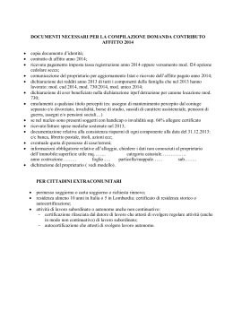
CUOCIWÜRSTEL
ROSTBRÄTER
SAUSAGE GRILL
GRILLS SAUCISSES BARREAUDES
ASADOR DE SALCHICHAS
WORSTGRILLS
Mod. CWE-42
Mod. CWE-42/2
MOD. GE62TPS
MOD. GE63TPS
Mod. CWE-62
Mod. CWE-62/2
MOD. OCWE-42 115037
MOD. OCWE-42/2
MOD. OCWE-62
MOD. OCWE-62/2
30378-01
AVVERTENZE D’INSTALLAZIONE, DI REGOLAZIONE,
D’IMPIEGO E DI MANUTENZIONE (pagina 2-5)
NOTICES D’INSTALLATION, DE REGLAGE, D’EMPLOI ET
D’ENTRETIEN (page 14-17)
AUFSTELLUNGS-, GEBRAUCHS- UND INSTANDHALTUNGS-ANWEISUNGEN (Seite 6-9)
INSTRUCCIONES DE INSTALACION, REGULACION, USO
Y MANTENIMIENTO (plana 18-21)
INSTRUCTION FOR INSTALLATION, ADJUSTMENT, USE
AND MAINTENANCE (page 10-13)
AANWIJZINGEN VOOR DE INSTALLATIE, DE AFSTELLING,
HE GEBRUIK EN HET ONDERHOUD (pagina 22-25)
APPENDICE - ANHANG - APPENDIX - APPENDICE - APENDICE - AANHANGSEL (26)
*
*
*
* * **
*
* * **
Leggere attentamente il libretto e conservarlo con cura per tutta
la durata del prodotto.
Leggere subito le avvertenze!
Lire attentivement le manuel et le conserver avec soin pour toute
la durée du produit.
Lire tout de suite les avertissements!
Die Geräteanweisung aufmerksam lesen und für die ganze
Gerätedauer sorgfältig aufbewahren.
Die Hinweise sollen sofort gelesen werden!
Leer atentamente el manual y conservarlo con atención por toda
la durada del producto.
Leer enseguida las Advertencias!
Read the manual with attention and keep it carefully for the
whole duration of the appliance.
Read the warning remarks immediately!
Lees de handleiding aandachtig en bewaar het zorgvuldig
gedurende de hele levensduur van het apparaat.
Lees de waarschuwingen onmiddellijk!
Doc. No.
6
30378-016
0404
IT
INDICE
ISTRUZIONI PER L’INSTALLAZIONE --------------------------------------------------------------AVVERTENZE -------------------------------------------------------------------------------------------------------INSTALLAZIONE ---------------------------------------------------------------------------------------------------Posizionamento
Montaggio
Unione in linea delle apparecchiature
Collegamenti elettrici della cucina
Collegamento di terra ed equipotenziale
Collegamento idraulico
MESSA IN FUNZIONE ----------------------------------------------------------------------------------------------Verifica funzionamento impianto elettrico
Verifica della potenza termica nominale
ANALISI DI ALCUNI MALFUNZIONAMENTI ----------------------------------------------------------------------La griglia di cottura non si riscalda
Difficoltosa o mancata regolazione temperatura della griglia di cottura
SOSTITUZIONE PARTI SOGGETTE A RICAMBIO ------------------------------------------------------------------Resistenze di riscaldamento
Termostato di regolazione temperatura
Termostato di sicurezza
ISTRUZIONI PER L’USO E LA MANUTENZIONE ---------------------------------------------AVVERTENZE -------------------------------------------------------------------------------------------------------Dispositivi di sicurezza supplementari
USO -----------------------------------------------------------------------------------------------------------------Griglia di cottura
Spegnimento riscaldamento della griglia di cottura
PULIZIA E MANUTENZIONE ---------------------------------------------------------------------------------------Pulizia griglia di cottura
ELENCO PARTI SOGGETTE A RICAMBIO --------------------------------------------------------------------------
pag. ---- 3
pag. ---- 3
pag. ---- 3
pag. ---- 3
pag. ---- 4
pag. ---- 4
pag. ---- 4
pag. ---- 4
pag. ---- 4
pag. ---- 5
pag. ---- 5
APPENDICE ------------------------------------------------------------------------------------------------------ pag. -- 23
2/27
Cuociwürstel
ISTRUZIONI PER L’INSTALLAZIONE
AVVERTENZE
Installazione, adattamenti e manutenzione
dell’apparecchiatura devono essere effettuati da
installatori qualificati e autorizzati, in conformità
alle normative di sicurezza in vigore.
Il costruttore declina ogni responsabilità
qualora tale obbligo non venga rispettato.
ta portata (con un’apertura dei contatti di almeno 3 mm) e dispositivi di protezione automatici
differenziali ad alta sensibilità. Essi devono garantire la protezione contro il contatto diretto e
indiretto delle parti in tensione e contro le correnti
di guasto verso terra, secondo le Norme (corrente
massima di dispersione ammessa 1 mA/kW).
INSTALLAZIONE
Collegamento di terra ed equipotenziale
– È necessario collegare a terra l’apparecchiatura
sui morsetti contraddistinti con il simbolo
posti accanto alla morsettiera di arrivo linea.
– Collegare inoltre la struttura metallica di tutte
le apparecchiature elettriche installate, sui morsetti contraddistinti con il simbolo
posti
vicino a quelli di terra (sistema equipotenziale).
Posizionamento
– Le dimensioni di ingombro/allacciamento e i dati
tecnici sono riportati nelle pagine in appendice.
– Installare l’apparecchiatura in locali sufficientemente aerati.
– Posizionare l’apparecchiatura ad almeno 10 cm
dalle pareti circostanti. Tale distanza può essere inferiore quando le pareti sono incombustibili
o protette da isolante termico.
– L’apparecchiatura non è adatta per l’incasso.
Collegamento idraulico per Mod.CRE
– L’apparecchiatura é dotata di tubo in gomma
flessibile con raccordo da 3/4". Collegare l'apparecchiatura alla rete dell'acqua fredda con
campo di pressione da 1,5 -2,5 Bar, corredata di
rubinetto di arresto.
Collegare lo scarico troppo pieno mediante tubo
in gomma diametro 25 interno e collegarlo al
sifone di rete.
ATTENZIONE
Le apparecchiature sono conformi alla Direttiva
CEE n. 89/336 relativa alla compatibilità elettromagnetica.
Montaggio
– Rimuovere la pellicola che protegge i pannelli
esterni. Il collante eventualmente rimasto su
questi va tolto con idoneo solvente.
– Livellare l’apparecchiatura agendo sui piedini
regolabili.
– Montare la prolunga camino (se prevista) seguendo le istruzioni allegate alla prolunga stessa.
Unione in linea delle apparecchiature
– Accostare tra loro le apparecchiature e livellarle alla medesima altezza.
– Unirle utilizzando gli appositi coprigiunti di
unione (forniti a richiesta).
Collegamenti elettrici
– L’apparecchiatura è predisposta per funzionare alla tensione indicata sulla targhetta
dell’apparecchiatura.
– Ogni apparecchiatura deve essere alimentata con
una linea elettrica indipendente opportunamente
dimensionata (la potenza totale è riportata nella
tabella “Dati tecnici”) collegandola sull’apposita
morsettiera di arrivo linea con un cavo flessibile in
gomma avente caratteristiche di isolamento non
inferiori al tipo H 07 RN-F.
– La lunghezza dei conduttori fra il pressacavo ed
i morsetti di allacciamento dev’essere tale che i
conduttori attivi si tendano prima del conduttore di terra (giallo-verde) qualora il cavo dovesse
uscire dal pressacavo.
– È necessario installare appositi interruttori
onnipolari automatici di protezione, di adegua-
MESSA IN FUNZIONE
Verifica funzionamento impianto elettrico ed
idraulico
– Mettere in funzione l’apparecchiatura secondo
le istruzioni per l’uso, verificare la regolarità di
funzionamento dei dispositivi di comando del
riscaldamento della griglia di cottura e del carico acqua per mod.CRE. Provare le varie temperature di funzionamento.
Per il Mod.CWE
Oltre al termostato di lavoro, l’apparecchiatura
è dotata di un termostato di sicurezza che interviene interrompendo l’alimentazione elettrica
alle resistenze in caso di funzionamento anomalo del termostato principale.
Per il Mod.CRE
– Premere l'interruttore luminoso 0/1.
– Premere il pulsante verde con simbolo carico
acqua e tenerlo premuto finché l'acqua non
raggiunge il livello minimo.
– Scegliere la temperatura per la cottura desiderata ruotando la manopola del regolatore di
energia. Posizione 1 (temperatura minima),
Posizione 6 (temperatura massima).
_ Termostato di lavoro che rigenera l'acqua in
vasca quando la temperatura della stessa supera i 70°C. In questa fase di rigenerazione acqua
in vasca il gruppo riscaldante non funziona.
Verifica della potenza termica nominale
– Dopo l’installazione e dopo ogni intervento di
manutenzione controllare la potenza termica
dell’apparecchiatura.
Cuociwürstel
3/27
– La potenza termica nominale è riportata nella
tabella “Dati tecnici”.
– L’apparecchiatura funziona alla potenza termica nominale prevista quando la tensione di
alimentazione elettrica è quella indicata nella
Tabella T1.
ATTENZIONE
Se i valori dell’alimentazione elettrica, non rientrano nei limiti indicati nella Tabella T1, interrompere il funzionamento dell’apparecchiatura e
contattare l’Ente di erogazione dell’energia elettrica.
ANALISI DI ALCUNI MALFUNZIONAMENTI
La griglia di cottura non si riscalda
– Controllare le valvole fusibili.
– Interruttore generale di alimentazione elettrica non inserito.
– Tensione di alimentazione insufficiente o errato collegamento elettrico dell’apparecchiatura.
– Termostato di regolazione temperatura o
regolatore di energia per mod.CRE difettoso.
– Resistenze difettose, male collegate o bruciate.
– Termostato di sicurezza intervenuto (da ripristinare) per avaria del dispositivo principale di regolazione della temperatura per Mod.CWE.
Difficoltosa o mancata regolazione temperatura
della griglia di cottura
– Tensione di alimentazione insufficiente o errato collegamento elettrico dell’apparecchiatura.
– Termostato di regolazione della temperatura o
regolatore di energia per Mod.CRE difettoso.
– Resistenze difettose, male collegate o bruciate.
SOSTITUZIONE PARTI SOGGETTE A RICAMBIO
IMPORTANTE Prima di procedere a riparazioni,
togliere tensione all’apparecchiatura disinserendo l’interruttore generale di corrente e chiudere
l'alimentazione acqua per mod.CRE.
I componenti sigillati non devono essere manomessi.
Per accedere ai particolari dell’impianto elettrico
e ai dispositivi di comando/sicurezza, togliere il
cruscotto dell'apparecchiatura ed eventualmente
la griglia di cottura.
Resistenze riscaldamento
– Rimuovere la griglia di cottura. Rimuovere la
protezione resistenze. Togliere e sostituire il
componente.
Termostato di sicurezza per Mod.CWE
– Rimuovere il cruscotto, staccare il componente
da sostituire, scollegare dal cablaggio, sfilare il
bulbo ad esso collegato dalla propria sede, quindi sostituire il componente.
Mancata rigenerazione acqua in vasca per mod.
CRE
- Termostato di lavoro difettoso
- Elettrovalvola carico acqua difettosa
- Rimuovere il cruscotto, staccare il componente
da sostituire, scollegare dal cablaggio e sostituire il componente
ISTRUZIONI PER L’USO E LA
MANUTENZIONE
AVVERTENZE
Apparecchiatura con superfici calde!
L’apparecchiatura è destinata ad un uso
professionale e deve essere utilizzata da personale
addestrato. Essa va adibita alla cottura dei cibi.
Ogni altro impiego è considerato improprio.
L’installazione, e la trasformazione ad altra
tensione di alimentazione elettrica (se prevista),
devono essere effettuate da installatori qualificati
e autorizzati.
In caso di guasto disinserire l’interruttore generale
di alimentazione elettrica installato a monte
dell’apparecchiatura e chiudere il rubinetto
alimentazione acqua.
I componenti sigillati non devono essere manomessi.
Per la riparazione rivolgersi solo a centri di assistenza
autorizzati ed esigere parti di ricambio originali.
Il costruttore declina ogni responsabilità
qualora tali obblighi non vengano rispettati.
Leggere attentamente il presente libretto e
conservarlo con cura. Prima di utilizzare
l’apparecchiatura pulire accuratamente tutte le
superfici destinate ad entrare in contatto con i cibi.
Dispositivi di sicurezza supplementari Mod.CWE
L’apparecchiatura è dotata di termostato di sicurezza supplementare a ripristino manuale, che
blocca automaticamente l’alimentazione elettrica
alle resistenze, quando la temperatura della griglia di cottura supera la temperatura massima di
funzionamento consentita (termostato di lavoro in
avaria). Se l’inconveniente si verificasse, disinserire l’alimentazione elettrica all’apparecchiatura
e avvisare il servizio di assistenza.
USO
Termostato regolazione temperatura per Mod.CWE
Regolatore di temperatura per Mod.CRE
– Rimuovere il cruscotto, staccare il componente
da sostituire, scollegare dal cablaggio, sfilare il
bulbo ad esso collegato dalla propria sede, quindi sostituire il componente.
4/27
Cuociwürstel
Griglia di cottura
Per mettere in funzione il riscaldamento della
griglia di cottura (lampade spia verde e arancio
accese), è necessario ruotare la manopola del termostato di regolazione della temperatura o
regolatore di energia in corrispondenza dei seguenti riferimenti:
Per Mod.CWE:
0
Spento
50 °C
Temperatura minima
Mod.CRE e spazzolare o lavare a parte i componenti.
– Risciacquare normalmente e asciugare.
Per Mod.CRE:
ELENCO PARTI SOGGETTE A RICAMBIO PER MOD.CWE
– Resistenze griglia di cottura
– Settori in ghisa della griglia di cottura
– Manopola termostato regolazione temperatura
– Lampade spia
– Termostato regolazione temperatura
– Termostato di sicurezza
0
1
2
3
4
5
6
ELENCO PARTI SOGGETTE A RICAMBIO PER MOD.CRE
– Interruttore generale 0/1
– Pulsante di carico acqua
– Elettrovalvola
– Regolatore di energia
– Termostato di lavoro
– Resistenze griglie di cottura
100-200 °C Temperature intermedie
300°C
Temperatura max. (circa)
Spento
50°C
90°C
120°C
150°C
200°C
270°C
Spegnimento riscaldamento griglia di cottura
– Per disinserire il riscaldamento o l’alimentazione elettrica, ruotare le manopole dei termostati
o regolatore di energia in posizione 0.
PULIZIA E MANUTENZIONE
– Prima di eseguire qualunque operazione di pulizia staccare l’alimentazione elettrica.
– Pulire giornalmente le superfici in acciaio inox
con acqua e comuni detersivi non abrasivi, sciacquare bene e asciugare accuratamente.
– Non usare pagliette di ferro o prodotti contenenti cloro.
– Nelle operazioni di movimentazione del cibo
durante la cottura o di pulizia della griglia di
cottura, non usare impropriamente oggetti
appuntiti che possano causare danni alle resistenze poste sotto le nervature.
– Non usare prodotti corrosivi per la pulizia del
pavimento sottostante l’apparecchiatura
– Non lavare l’apparecchiatura con getti d’acqua
– Prima di un lungo periodo di inattività dell’apparecchiatura disinserire l’interruttore principale di corrente installato a monte della stessa e
chiudere il rubinetto di alimentazione acqua
per Mod.CRE. Procedere alla sua accurata
pulizia.
– Richiedere, almeno due volte l’anno, l’intervento di un tecnico autorizzato per il controllo
dell’apparecchiatura. È opportuno in ogni caso
stipulare un contratto di manutenzione.
Pulizia griglia di cottura
– Non utilizzare prodotti aggressivi (es. spray per
forni).
– È necessario tenere costantemente pulita la
griglia di cottura e staccare gli eventuali residui
di cibo alla fine di ogni cottura. Tali residui di
cibo si possono eliminare facilmente togliendo i
settori in ghisa che compongono la griglia di
cottura per il Mod.CWE o la griglia inox per
Cuociwürstel
5/27
DE
INHALTSVERZEICHNIS
INSTALLATIONSANWEISUNGEN --------------------------------------------------------------------HINWEISE ---------------------------------------------------------------------------------------------------------INSTALLATION ----------------------------------------------------------------------------------------------------Aufstellung
Montage
Verbindung der Geräte in Batterie
Elektroanschluß
Erdungs- und Potentialausgleichsanschlüsse
Wasseranschluß
INBETRIEBNAHME ------------------------------------------------------------------------------------------------Funktionskontrolle der Elektroanlage
Überprüfung der Nennwärmebelastung
ANALYSEN EINIGER BETRIEBSSTÖRUNGEN --------------------------------------------------------------------Der Grillrost heizt nicht
Mangelnde Temperaturregelung
AUSTAUSCH DER VERSCHLEISSTEILE ---------------------------------------------------------------------------Heizkörper
Betriebsthermostat
Sicherheitsthermostat
GEBRAUCHS- UND INSTANDHALTUNGSANWEISUNGEN ------------------------------HINWEISE ---------------------------------------------------------------------------------------------------------Sicherheitsvorrichtungen
GEBRAUCH --------------------------------------------------------------------------------------------------------Betrieb
Ausschalten der Beheizung
REINIGUNG UND WARTUNG --------------------------------------------------------------------------------------Reinigung des Grillrostes
LISTE DER VERSCHLEISSTEILE -----------------------------------------------------------------------------------
Seite ---- 7
Seite ---- 7
Seite ---- 7
Seite ---- 7
Seite ---- 7
Seite ---- 8
Seite ---- 8
Seite ---- 8
Seite ---- 8
Seite ---- 8
Seite ---- 9
ANHANG ------------------------------------------------------------------------------------------------------------ Seite -- 23
6/27
Rostbräter
INSTALLATIONSANWEISUNGEN
HINWEISE
Installation, Anpassung und Wartung der Geräte
müssen durch zugelassene Betriebe oder Installateure in Übereinstimmung mit den geltenden
Sicherheitsvorschriften durchgeführt werden.
Der Hersteller lehnt jegliche Verantwortung
ab, wenn dieser Verpflichtung nicht nachgekommen wird.
ACHTUNG Die Geräte entsprechen bezüglich der
EMV EG-Richtlinie Nr. 89/336.
INSTALLATION
Aufstellung
– Die Abmessungen, der Anschluß und die
technischen Daten sind auf den im Anhang
beigefügten Seiten aufgeführt.
– Das Gerät nur in ausreichend belüfteten
Räumen aufstellen.
– Das Gerät in einem Abstand von mindestens
10 cm von den umgebenden Wänden aufstellen.
– Das Gerät ist nicht für den Einbau geeignet.
Montage
– Den Schutzfilm von den Außenwänden entfernen. Eventuell zurückbleibende Klebstoffreste
mit geeigneten Lösungsmitteln entfernen.
– Das Rückseiten-Füllstück (falls vorgesehen)
montieren (siehe dem Teil beigefügte Anleitungen).
Verbindung der Geräte in Batterie
– Die Geräte aneinander stellen und auf die
gleiche Höhe ausrichten.
– Die Geräte unter Verwendung der auf Anfrage
mitgelieferten Fugenabdeckungen untereinander verbinden.
Elektroanschluß
– Die Geräte sind für den Betrieb mit der auf dem
Typenschild des Gerätes angegebenen
Spannung vorgesehen.
– Jedes Gerät muß durch eine unabhängige, der
Gesamtleistung entsprechend dimensionierte
elektrische Leitung versorgt werden (Gesamtleistung der Tabelle “Technische Daten” entnehmen); indem es mittels flexiblen Kabel aus Isoliergummi (mindestens Typ H07RN-F) an die
Anschlussklemmenleiste angeschlossen wird.
– Die Leitung zwischen Kabeldurchgang und
Klemmenleiste soll so lange sein, dass die
Stromleitenden Kabel sich vor dem Erdleiter
(gelb-grün) spannen.
– Es müssen geeignete automatische allpolige
Schutzschalter, mit einer entsprechenden
Leistung (und einer Kontaktöffnungsweite von
mindestens 3 mm) installiert werden, sowie
hochsensible automatische Differentialschutz-
schalter. Diese müssen eine ausreichende
Sicherheit, entsprechend den einschlägigen
Vorschriften, gegen einen direkten bzw.
indirekten Kontakt mit den spannungsführenden
Teilen oder dem Fehlerstrom zur Erdung,
gewährleisten (höchst zulässiger Fehlerstrom
1 mA/kW).
Erdungs- und Potentialausgleichsanschlüsse
– Die Geräte müssen mittels den mit Symbol
markierten Klemmen neben dem EingangsKlemmbrett geerdet werden.
– Darüberhinaus ist die Metallkonstruktion aller
installierten Elektro-Geräte an die Klemmen
mit Symbol
in der Nähe der Erdklemmen
anzuschliessen (Potentialausgleichssystem).
Wasseranschluß für Typen CRE
– Das Gerät wird mit einem Schlauch von 3/4
ausgeliefert.Der Netzwasserdruck muss
zwischen 1,5 und 2,5 bar betragen,dass Wasser
muß Kalt sein, vor dem Gerät muss ein
Wasserabsperrhahn vorgeschaltet werden.
Den Wasserabfluss mittels einem Schlauch mit
Innendurchmesser 25mm an das Abwasser, mit
Siphon, vom Gehaüse anschließen
INBETRIEBNAHME
Funktionskontrolle der Elektroanlage und
Wasserzufuhr
– Das Gerät entsprechend den Gebrauchsanweisungen in Betrieb setzen, und die regelmässige
Funktion der Steuerungsvorrichtungen und der
Heizung überprüfen und das Aufladen vom
Wasser für die Typen CRE. Die verschiedenen
Betriebspositionen des Gerätes testen.
Für die Typen CWE:
Zusätzlich zum Betriebsthermostat ist jedes
Gerät mit einem Sicherheitsthermostat, der die
Stromversorgung bei Betriebsstörungen
unterbricht, ausgestattet.
Für die Typen CRE:
– Hauptschalter 0/1 einschalten.
– Die Grüne Taste, mit dem Symbol Wasser
aufladen, drücken und eingedrückt halten bis
das Wasserniveau die Minimum Wasserhöhe
erreicht.
– Die Gartemperatur wählen mittels den
Drehknopf. Position 1 (niedrige Temperatur),
Position 2 (höchste temperatur).
– Ein Temperaturregler regeneriert den
Wasserniveau in automatisch wenn die
Temperatur vom Wasser circa 70°C erreicht. In
diesem Fall werden die Heizelemente
automatisch ausgesetzt, für die Zeit der
Regenerierung vom Wasser.
Überprüfung der Nennwärmebelastung
– Nach der Installation und nach jedem
Wartungseingriff ist die Wärmebelastung des
Rostbräter
7/27
Gerätes zu überprüfen.
– Die Nennwärmebelastung ist in der Tabelle
“Technische Daten” aufgeführt.
– Das Gerät funktioniert bei Nennwärmebelastung, wenn die Stromspannung der in Tabelle T1 angegebenen entspricht.
ACHTUNG!
Sollte sich die Spannung nicht innerhalb der in
Tabelle T1 angegebenen Grenzen befinden, den
Betrieb der Gerätes unterbrechen und das
Stromversorgungsunternehmen kontaktieren.
ANALYSEN EINIGER BETRIEBSSTÖRUNGEN
Der Grillrost heizt nicht
– Die Sicherungen kontrollieren
– Hauptschalter ausgeschaltet
– Spannung unzureichend oder falscher
Elektroanschluß
– Betriebsthermostat defekt
– Heizkörper falsch angeschlossen oder defekt
– Sicherheitsthermostat ist eingegriffen oder
Temperaturregler defekt (nur für Typen CRE).
Mangelnde Temperaturregelung
– Spannung unzureichend oder falscher
Elektroanschluß
– Betriebsthermostat Temperaturregler defekt
(nur für Typen CRE).
– Heizkörper falsch angeschlossen oder defekt.
AUSTAUSCH DER VERSCHLEISSTEILE
WICHTIG. Vor der Durchführung jeglicher Wartungsarbeiten ist durch Betätigung des Hauptschalters die Stromzufuhr und Wasserzufuhr zum
Gerät zu unterbrechen.
Die versiegelten Bauteile dürfen nicht manipuliert werden.
Um auf die Komponenten der elektrischen Anlage
und die Steuer-/Sicherheitsvorrichtungen
zuzugreifen, die Schaltblende des Geräts und
eventuell die Gußteile der Grillfläche und
eventuelldie grillrostre abnehmen.
Heizkörper
– Die Gußteile der Grillfläche abnehmen. Die
Halterungen der Heizkörper entfernen.
Heizkörper und eventuell die Grillroste
abnehmen und ersetzen.
Betriebsthermostat für die Typen CWE
Betriebstemperaturregler für die Typen CRE
– Die Bedienblende entfernen, Thermostat
abnehmen und abhängen, Meßkugel aus ihrem
Sitz abnehmen. Das Bauteil austauschen.
Sicherheitsthermostat nur für die Typen CWE
– Die Bedienblende entfernen, Thermostat
abnehmen und abhängen, Meßkugel aus ihrem
Sitz abnehmen. Das Bauteil austauschen.
8/27
Rostbräter
Fehlende Wasser Regenerierung imwanne für die
Typen CRE
– RegelThermostat defekt
– Magnet Wasserfüllung defekt.
– Die Bedienblende entfernen und das defekte
Bauteil austauschen.
GEBRAUCHS- UND
INSTANDHALTUNGSANWEISUNGEN
HINWEISE
Gerät mit heißen Oberflächen!
Das Gerät ist für den professionellen Gebrauch
bestimmt, muß von Fachkräften bedient werden, die
mit dem Garen von Speisen vertraut sind und dient
zum Garen von Speisen. Jede andere Verwendung ist
als ungeeignet zu erachten.
Die Installation und die Umstellung auf andere
Spannung (falls möglich) müssen von qualifizierten
und zugelassenen Installateuren durchgeführt
werden.
Im Falle eines Defektes ist die Stromversorgung und
Wasserzufuhr zu unterbrechen.
Die versiegelten Bauteile dürfen nicht manipuliert
werden.
Für die Reparatur sind lediglich die zugelassenen
Kundendienstzentren zu konsultieren und OriginalErsatzteile zu verlangen.
Der Hersteller lehnt jegliche Verantwortung
ab, wenn diesen Verpflichtungen nicht
nachgekommen wird.
Das vorliegende Handbuch ist aufmerksam durchzulesen und sorgfältig aufzubewahren. Vor dem Gebrauch des Gerätes sind alle Oberflächen, welche mit
den Speisen in Berührung kommen, sorgfältig zu
reinigen.
Sicherheitsvorrichtungen nur für die Typen CWE
Die Geräte sind mit einem zusätzlichen
Sicherheitsthermostat mit manueller Rückstellung ausgestattet, der die Stromversorgung
der Widerstände automatisch unterbricht, sobald
die Temperatur der Platte die maximale
Betriebstemperatur überschreitet (Betriebsthermostat defekt). Falls eine solche Störung
auftritt, die Stromversorgung des Geräts abhängen
und den Kundendienst hinzuziehen.
GEBRAUCH
Betrieb
Um die Beheizung anzuschalten (grüne und orange
Kontrollampen an) ist es notwendig den Knebel
des Betriebsthermostates auf die gewünschte
Arbeitsposition zu bringen.
Typen CWE:
0
50 °C
100-200 °C
300 °C
Typen CRE:
ausgeschaltet
Mindesttemperatur
Zwischentemperaturen
Höchsttemperatur
LISTE DER VERSCHLEISSTEILE
0
ausgeschaltet
1
50°C
2
90°C
3
120°C
4
150°C
5
200°C
6
270°C
Ausschalten der Beheizung
– Den Knebel des Betriebsthermostates oder
Betriebstemperaturregler auf Position 0 drehen.
–
–
–
–
–
–
Hauptschalter 0/1
Füllschalter Wasserniveau
Magnet Wasserfüllung
Temperaturregler (Energie Regler)
Thermostat (Wasserniveau)
Heizelemente
REINIGUNG UND WARTUNG
– Vor der Durchführung irgendeiner Reinigungsarbeit ist die elektrische Stromversorgung zu
unterbrechen.
– Die Oberflächen aus rostfreiem Edelstahl täglich
mit Wasser und handelsüblichen nicht
scheuernden Reinigungsmitteln reinigen,
nachspülen und sorgfältig trocken reiben.
– Keine Putzkissen aus Stahlwolle oder
chlorhaltige Produkte verwenden.
– Für das Umdrehen des Garguts oder die
Reinigung des Grillrostes keine spitzen
Gegenstände, welche die Heizkörper
beschädigen könnten, verwenden.
– Keine spitzen Gegenstände verwenden, welche
die Oberfläche aus Stahl verkratzen und
beschädigen könnten.
– Keine korrosiven Produkte für die Reinigung
des Bodens unterhalb des Gerätes verwenden.
– Das Gerät nicht mit einem Wasserstrahl
reinigen.
– Vor einer längeren Stillegung des Gerätes den
vorgeschalteten Hauptschalter ausschalten und
die Wasserzufuhr schließen, nur für die Typen
CRE.Eine sorgfältige Reinigung vornehmen.
– Mindestens zweimal pro Jahr den Eingriff eines
zugelassenen Technikers für die Kontrolle des
Gerätes anfordern. In jedem Fall wird der
Abschluß eines Wartungvertrages empfohlen.
Reinigung der Grillfläche
– Keine aggressiven Mittel verwenden (z.B.
Backofenspray).
– Der Gargrill muß stets sauber gehalten und
nach dem Garen sorgfältig von eventuellen
Speiseresten befreit werden. Dazu einfach die
Grillroste herausnehmen und separat
abbürsten oder spülen.
– Wie gewohnt nachspülen und trocknen.
(nur für die Typen
CWE)
Heizkörper
Gußteile der Grillfläche
Knebel des Betriebsthermostates
Kontrollampen
Betriebsthermostat
Sicherheitsthermostat
LISTE DER VERSCHLEISSTEILE
–
–
–
–
–
–
Rostbräter
9/27
GB
INDEX
INSTALLATION INSTRUCTIONS ---------------------------------------------------------------------WARNINGS ---------------------------------------------------------------------------------------------------------INSTALLATION ----------------------------------------------------------------------------------------------------Positioning
Assembly
In line union of the appliances
Electrical connection
Earth and unipotential connections
Hydraulic system connection
START-UP ----------------------------------------------------------------------------------------------------------Function check
Nominal heat input check
ANALYSIS OF SEVERAL FAILURES -------------------------------------------------------------------------------Cooking grate does not heat up
Diffcult or lacking temperature adjustment
REPLACEMENT OF PARTS SUBJECT TO CHANGE ---------------------------------------------------------------Heating elements
Regulation thermostat
Safety thermostat
USE AND MAINTENANCE --------------------------------------------------------------------------------WARNINGS ---------------------------------------------------------------------------------------------------------Safety devices
USE ----------------------------------------------------------------------------------------------------------------Operation
Switching off heating
CLEANING AND MAINTENANCE ----------------------------------------------------------------------------------Cleaning of cooking grate
LIST OF PARTS SUBJECT TO CHANGE ----------------------------------------------------------------------------
page -- 11
page -- 11
page -- 11
page -- 11
page -- 11
page -- 11
page -- 12
page -- 12
page -- 12
page -- 12
page -- 13
APPENDIX --------------------------------------------------------------------------------------------------------- page -- 24
10/27
Sausage grill
INSTALLATION INSTRUCTIONS
WARNINGS
Installation, adjustments and maintenance of the
appliances must be done by authorized installers,
in accordance with the safety standards in force.
The manufacturer declines any responsibility
if such obligation is not observed.
NOTE:
Appliances are in accordance with the EEC
Directive 89/336 on the electromangetic
compatibility.
INSTALLATION
Positioning
– The overall/connection dimensions and the
technical data are stated in the pages in the
appendix.
– Install the appliances only in sufficiently aired
rooms.
– Position appliances at least 10 cm from the
nearby walls.
– The appliances are not suitable for built-in
installation.
Assembly
– Remove the film which protects the external
panels. Any glue remaining on these is to be
removed with a suitable solvent.
– Level appliance by means of the adjustable feet.
– Assemble the spacer (if foreseen) by following
the instructions enclosed with the spacer itself.
In line union of the appliances
– Put the appliances next to eachother and level
them at the same height.
– Unite the appliances using the special union
joint-coverings supplied upon request.
Electrical connections
– Appliances are designed to operate at the voltage
indicated on the rating plate.
– Each appliance must be connected to an
independent mains supply of suitable capacity
(total power indicated in “Technical data” table)
via an input terminal board with flexible rubber
cable, insulated at a level not below H07RN-F.
– Make sure that the cables lenght allows for the
live wires to disconnect from terminal block
before the yellow/green ground wire, in case of
simultaneous pull.
– Automatic cutout omnipolar switches of suitable
capacity (with contacts opening to at least 3
mm) and highly sensitive automatic differential
protective devices must be fitted. These must
ensure that there is no direct or indirect contact
between live components and fault currents
and the ground, in accordance with current
regulations (maximum admissible leakage
current 1 mA/kW).
Earth and unipotential connections
– Appliances must be earthed on terminals marked
with the symbol
.
– Connect the metallic structure of every electrical
appliance installed to the terminals, marked by
the symbol
, and located next to the earth
terminals (unipotential system).
Hydraulic system connection for the Mod.CRE
- The product is provided with a rubber hose with
_” fitting. Connect the product by way of a
stopcock to a cold water supply delivering
pressure of between 1.5-2.5 Bar.
Connect the overflow outlet to the waste trap
with a rubber hose (25 internal diameter)
START-UP
Function check electrical and hydraulic system
– Start-up the appliance following the instructions
given; check function regularity and make sure
that the controls ,heating elements and water
filling for mod.CRE are in good working order.
Testing them with the various function positions.
For the Mod.CWE
Appliances are provided with a safety
thermostat which cuts off power supply to
heating elements if regulation thermostat is
faulty.
For the Mod.CRE
- Press the luminous switch 0/1.
- Press and hold the green button with the filler
symbol until the water reaches the minimum
level.
- Select the cooking temperature by turning the
control knob. Position 1 (minimum temperatu
re), Position 6 ( maximum temperature).
- The water in the tank is regenerated
thermostatically when the temperature
exceeds 70 °C. The heating unit is deactivated
while regeneration is in progress.
Nominal heat input check
– After installation and at each maintenance
intervention check the heat input of the
appliance.
– The nominal heat input is stated in the
“Technical data” table.
– The appliance operates at the nominal heat
input when the electrical power is the one stated
in Table T1.
ATTENTION If the power supply value is not
within the limits indicated in Table T1, interrupt
the operation of the appliance and contact the
electricity delivery body.
ANALYSIS OF SEVERAL FAILURES
Cooking grate does not heat up
– Check fuse valves
– Main switch off
– Insufficient power or wrong electrical connection
– Regulation thermostat or heat regulator for
Sausage grill
11/27
Mod.CRE faulty
– Wrong connection or elements faulty
– Safety thermostat activated or faulty for
Mod.CWE
Diffcult or lacking temperature adjustment
– Insufficient power or wrong electrical connection
– Regulation thermostat or heat regulator for Mod.
CRE faulty
– Wrong connection or elements faulty
REPLACEMENT OF PARTS SUBJECT TO CHANGE
IMPORTANT Before carrying out repairs, unplug
appliance from mains disconnecting the main
switch and close the feeder water for Mod.CRE.
Sealed components must not be tampered
with.
To reach electrical components, i.e. controls and
safety devices, remove the front panel and if
necessary the cooking grate.
Heating elements
– Remove the cast iron sections forming part of the
cooking grate. Remove heating elemnts support.
Disconnect and replace the faulty heating element.
Heat Regulator for Mod.CRE
Regulation thermostat for Mod. CWE
– Remove the front control panel. Remove the
thermostat and disconnect it. Extract the bulb
(thermostat) from its seat. Change the faulty
component.
Safety thermostat for Mod.CWE
– Pull out the control knobs. Remove the front
control panel. Remove the thermostat and
disconnect it. Extract the bulb (thermostat) from
its seat. Change the faulty component.
Tank water regeneration failure for CRE mod.
– Working thermostat faulty.
– Electric valve faulty.
– Remove control panel and change the
faulty component.
USE AND MAINTENANCE
WARNINGS
Caution , appliance with hot surfaces!
The appliance is for professional use and must be
used by trained personnel. It is for the cooking of
food. Any other use of the appliance is considered
improper.
The installation and adaptation to other voltage
must be done by qualified and authorized installers.
In case of breakdown disconnect the main switch
and close the feeder water tap.
Sealed components must not be tampered with.
For repairs consult only authorized service centres
12/27
Sausage grill
and ask for original spare parts only.
The manufacturer declines any responsability
if such obligations are not observed.
Carefully read this booklet and keep it in a safe place.
Before using the appliance carefully clean all the
surfaces that will come in contact with food.
Safety devices for Mod.CWE
The appliance is equipped with an additional
manually-reset safety thermostat which
automatically cuts off the electrical supply to the
heating elements when the temperature of the
cooking grate exceeds the maximum working temperature (operating thermostat faulty). If this
should occur, disconnect the appliance from the
mains electrical supply and contact your nearest
customer service centre.
USE
Operation
To switch on heating of cooking plate (green and
orange pilot lamps on) turn the thermostat knob
or heat regulator on the desired working position.
For Mod.CWE:
0
off
50 °C
minimum temperature
100÷200 °C intermediate temperatures
300 °C
maximum temperature
For Mod.CRE:
0
1
2
3
4
5
6
off
50°C
90°C
120°C
150°C
200°C
270°C
Switching off heating
– Turn thermostat knob or heat regulator on
position 0.
CLEANING AND MAINTENANCE
– Before any cleaning operation disconnect the
electrical supply (if present).
– Clean stainless steel surfaces daily with water
and non abrasive common detergents, rinse and
dry thoroughly.
– Do not use iron scouring pads or chlorate
products.
– Never use sharp tools to handle the food during
cooking or to clean the cooking grate, as these
may damage or ruin the heating elements located
below the grate.
– Do not use sharp objects which can scratch and
ruin the steel surface.
– Do not use corrosive products to clean the floor
under the appliance.
– Do not wash the appliance with water jets.
– Before a long period of inactivity disconnect the
main switch and close the feeder water tap for
Mod.CRE. Proceed to its thorough cleaning.
– At least twice a year, ask for the intervention of
an authorized technician authorized for checking
the appliance. It is advisable in any case to
stipulate a maintenance contract.
Cleaning cooking grate
– Never use strong chemical products (e.g. oven
spray).
– The cooking grate must be kept clean at all
times and food remains should always be
removed after use. Food spills and remains can
be easily removed, extracting the cast iron
elements making up the grate for Mod. CWE or
the inox cooking grate for Mod.CRE and brushing
or washing them separately.
– Rinse with water and dry.
LIST OF PARTS SUBJECT TO REPLACEMENT (FOR MOD.CWE)
–
–
–
–
–
–
Cooking grate heating elements
Cast iron elements on cooking grate.
Knob for thermostat
Pilot lamps
Thermostat
Safety thermostat
LIST OF PARTS SUBJECT TO REPLACEMENT (FOR
MOD.CRE)
– General Switch 0/1
– Water filling button
– Electric valve
– Heat regulator
– Thermostat
– Cooking grate heating elements
Sausage grill
13/27
FR
SOMMAIRE
INSTRUCTIONS POUR L’INSTALLATION -------------------------------------------------------- page -- 14
AVERTISSEMENTS ------------------------------------------------------------------------------------------------- page -- 14
INSTALLATION ----------------------------------------------------------------------------------------------------- page -- 14
Positionnement
Montage
Installation en linge des appareils
Raccordement électriques
Raccordements de terre et équipotentiel
Raccordement hydraulique
MISE EN MARCHE --------------------------------------------------------------------------------------------------
page -- 14
Vérification du fonctionnement
Vérification de la puissance thermique nominale
EXEMPLE DE MAUVAIS FONCTIONNEMENTS -------------------------------------------------------------------- page -- 14
La grille de cuisson ne chauffe pas.
Réglage de la température difficile ou pas de réglage
REMPLACEMENT DES PIECES DETACHEES ---------------------------------------------------------------------- page -- 15
Résistance de chauffage grille de cuisson
Thermostat de regulation
Thermostat de securité
INSTRUCTIONS POUR L’EMPLOI ET L’ENTRETIEN ---------------------------------------AVERTISSEMENTS -------------------------------------------------------------------------------------------------Dispositifs de sécurité supplémentaires
EMPLOI ------------------------------------------------------------------------------------------------------------Utilisation
Arrêt du chauffage
NETTOYAGE ET ENTRETIEN -------------------------------------------------------------------------------------Nettoyage de la grille de cuisson
LISTE DES PIECES DETACHEES -----------------------------------------------------------------------------------
page -- 15
page -- 15
page -- 15
page -- 15
page -- 16
APPENDICE ------------------------------------------------------------------------------------------------------ page -- 23
14/27 Grills saucisses barreaudes
INSTRUCTIONS POUR L’INSTALLATION
AVERTISSEMENT
L’installation, les adaptations et l’entretien de l’appareil doivent être effectués par des installateurs autorisés conformément aux normes de sécurité en vigueur.
Le constructeur décline toute responsabilité
en cas de non-respect de ces obligations.
ATTENTION Ces appareils sont conformes à la
directive CEE n. 89/336 concernant la compatibilité
eléctromagnetique.
contacts direct et indirect des parties sous
tension et des courants de défaut vers la terre,
conformément aux Normes (courant maximum
de fuite admis 1 mA/kW).
Raccordements de terre et équipotentiel
– L’appareil doit être raccordé à la terre sur les
bornes marquées du symbole
situées à côté des borniers d’arrivée de la ligne.
– Raccorder la structure métallique de tous les
appareils électriques installés sur les bornes
marquées du symbole
situées près des
bornes de terre (système équipotentiel).
INSTALLATION
Positionnement
– Les dimensions d’encombrement/raccordement
et les données techniques sont indiquées dans
les pages en appendice.
– Installez l’appareil dans des locaux
suffisamment aérés.
– Positionnez l’appareil à au moins 10 cm des
parois adjacentes.
– Cet appareil ne peut pas être encastré.
Montage
– Retirez le film de protection appliqué sur les
panneaux extérieurs. Si éventuellement il reste
de la colle, nettoyez-la avec un solvant adéquat.
– Mettez de niveau l’appareil en agissant sur les
pieds réglables.
– Montez la pièce de remplissage (si elle est prévue)
en suivant les instructions fournies.
Installation en ligne des appareils
– Disposez les appareils l’un à côté de l’autre et
mettez-les tous au même niveau.
– Unissez les appareils en utilisant les couvrejoints d’union spéciaux fournis sur demande.
Raccordements électriques
– L’appareil est prévu pour fonctionner à la tension
indiquée sur la plaquette signalétique.
– Chaque appareil doit être alimenté par une
ligne électrique indépendante correctement
dimensionnée (la puissance totale est indiquée
dans le tableau «Données techniques») avec
branchement sur le bornier d’arrivée de la ligne
prévu à cet effet à l’aide d’un câble flexible en
caoutchouc ayant des caractéristiques d’isolation
non inférieures au type H07RN-F.
– La longueur des conducteurs entre le passage
des cables et les bornes de branchement doît
être telle à permettre aux conducteurs actifs de
se tendre avant celui de terre (jaune-vert) en cas
de sortie du câble de sa presse.
– On doit installer des disjoncteurs omnipolaires
automatiques de protection, d’une portée
appropriée (avec une ouverture des contacts
d’au moins 3 mm) et des dispositifs de protection
automatiques différentiels à haute sensibilité.
Ils doivent garantir la protection contre les
Raccordement hydraulique pour mod. CRE
- L’appareil est équipé d’un tuyau en
caoutchouc flexible avec raccord _”.
Raccorder l’appareil à
l’installation d’eau froide à une pression de
1,5/2,5 bar avec un robinet.
Raccorder le conduit d’évacuation avec trop
plein au moyen d’un tuyau en caoutchouc, Ø
int. 25, relié au siphon du réseau.
MISE EN MARCHE
Vérification du fonctionnement
– Mettez l’appareil en marche selon les
instructions pour l’emploi. Vérifiez que le
fonctionnement des dispositifs de commande
de chauffage et la charge d'eau pour le Mod.
CRE est correcte en essayant les différentes
positions de fonctionnement.
– Outre le thermostat de travail, l’appareil est
équipé d’un thermostat de sécurité
supplémentaire qui bloque automatiquement
l’alimentation électrique des résistances en cas
de dysfonctionnement du thermostat de travail.
Pour le mod. CRE
- Appuyer sur l’interrupteur lumineux 0/1.
- Appuyer sur le bouton vert portant le
symbole de remplissage d’eau et garder le
doigt dessus jusqu’à ce que l’eau ait atteint le
niveau minimum.
- Choisir la température de cuisson en
tournant la manette du régulateur d’énergie.
Position 1 (température minimum), position 6
(température maximum).
- Thermostat de service qui régénère l’eau dans
la cuve lorsque la température de cette
dernière dépasse 70°C. Au cours de cette
phase de régénération de l’eau dans la cuve,
le groupe chauffant ne fonctionne pas.
Vérification de la puissance thermique nominale
– Contrôlez la puissance thermique de l’appareil
après avoir effectué l’installation et après chaque
opération d’entretien.
– La puissance thermique nominale est indiquée
dans le tableau des “Données Techniques”.
Grills saucisses barreaudes
15/27
Pour le Mod.CWE
L’appareil fonctionne à la puissance thermique
nominale lorsque la tension d’alimentation
életrique est celle indiquée dans le Tableau T1.
ATTENTION
Si les valeurs de tension d’alimentation électrique
ne rentrent pas dans les limites indiquées dans le
Tableau T1, il faut arrêter l’appareil et appeller la
Compagnie de l’électricité.
Régénération de l’eau dans la cuve non effectuée
pour mod. CRE
. Thermostat de service défectueux
. Electrovanne d’arrivée d’eau défectueuse
. Retirer le panneau de contrôle, déposer le
composant à remplacer, débrancher le câblage et
remplacer le composant pour le mod, CWE ou la
grille inox pour le mod. CRE.
INSTRUCTIONS POUR
L’EMPLOI ET L’ENTRETIEN
EXEMPLES DE MAUVAIS FONCTIONNEMENTS
La grille de cuisson ne chauffe pas.
– Contrôlez les fusibles.
– Interrupteur générale de courrant ne pas
branché.
– Tension insuffisante ou mauvais raccordement
électrique.
– Thermostat de régulation, regulateur de temp
pour le Mod.CRE sont défectueux.
– Mauvais raccordement des résistances ou bien
les résistances sont défectueux
– Intervention du thermostat de securité pour le
Mod.CWE.
Réglage de la température difficile ou pas de réglage
– Tension insuffisante ou mauvais raccordement
électrique.
– Thermostat de régulation, regulateur de temp
pour le Mod. CRE sont défectueux.
– Mauvais raccordement des résistances ou bien
les résistances sont défectueux.
REMPLACEMENT DES PIECES DETACHEES
IMPORTANT Avant de procéder à des réparations,
couper la tension de l’appareil à l’aide de
l’interrupteur général de courant et couper l’arrivée
d’eau pour le mod. CRE.
Il ne faut pas intervenir sur les composants
scellés.
Pour accéder aux éléments de l’installation électrique
et aux dispositifs de commande/sécurité, retirer le
panneau de commande de l’appareil et éventuellement la grille de cuisson.
Résistance de chauffage grille de cuisson
– Retirer les secteurs en fonte de la grille de
cuisson. Retirer la protection des résistances,
débrancher et remplacer le composant.
Regulateur de temp pour le Mod.CRE
Thermostat de regulation pour le Mod.CWE
– Retirer le panneau de commande, détacher et
débrancher le thermostat, extraire le bulbe de
son logement. Remplacer le composant.
Thermostat de securité pour le Mod.CWE
– Retirer le panneau de commande, détacher et
débrancher le thermostat, extraire le bulbe de
son logement. Remplacer le composant.
16/27
Grills saucisses barreaudes
AVERTISSEMENTS
Attention, surface très chaude.
L’appareil est destiné à un usage professionnel et doit
être utilisé par du personnel formé à cet effet. Il doit
être employé pour cuire des aliments. Tout autre
emploi de l’appareil sera considéré comme incorrect.
L’installation et l’adaptation à un autre type de
tension d’alimentation électrique (si prevue),
doivent être effectuées par des installateurs qualifiés
et autorisés.
En cas de panne, débranchez l’appareil.
Il ne faut pas intervenir sur les composants scellés.
Pour le dépannage, adressez-vous exclusivement
aux centres d’assistance autorisés et exigez des
pièces détachées d’origine.
Le fabricant décline toute responsabilité au
cas où ces obligations ne seraient pas respectées.
Lisez attentivement la présente notice et conservezla soigneusement. Avant d’utiliser l’appareil,
nettoyez avec soin toutes les superficies qui doivent
supporter des aliments
Dispositifs de sécurité suplémentaires pour le
Mod.CWE
Les appareils sont équipés d’un thermostat de securité supplémentaire. Ce dispositif répond en coupant
la tension de la grille de cuisson lorsque la température dépasse la limite maximale. Si cela se vérifie
il faut débrancher l’appareil et appeler un technicien.
EMPLOI
Utilisation
Pour brancher l’alimentation électrique (lampes
témoin allumées) tournez la manette du
thermostat ou regulateur de temp sur la position
désirée.
Pour le Mod.CWE:
0
Éteint
50 °C
Température mini
100÷200 °C
Températures intermédiaires
– Au moins deux fois par an, appelez un technicien
autorisé pour contrôler l’appareil.
Dans tous les cas, il est opportun de stipuler un
contrat d’entretien.
Nettoyage de la grille de cuisson
– Ne pas utiliser de produits agressifs (par ex.
produits en bombe pour fours).
– On doit toujours veiller à ce que la grille de
cuisson soit propre et à détacher les éventuels
restes d’aliments à la fin de chaque cuisson. On
peut éliminer facilement ces restes d’aliment en
retirant les secteurs en fonte qui forment la
grille de cuisson pour le mod, CWE ou la grille
inox pour le mod. CRE pour les brosser ou les
laver à part.
– Rincer normalement et sécher.
–
–
–
–
–
–
LISTE DES PIECES DETACHEES (MOD. CWE)
Resistance de la grille de cuisson
Secteurs en fonte de la grille de cuisson
Manette thermostat
Lampe témoin
Thermostat
Thermostat de securité
–
–
–
–
–
–
LISTE DES PIECES DETACHEES (MOD. CRE)
Interrupteur 0/1
Poussoir charge d'eau
Electrovanne
Regulateur de temp
Thermostat
Resistance de la grille de cuisson
Grills saucisses barreaudes
17/27
ES
INDICE
INSTRUCCIONES PARA LA INSTALLACION ---------------------------------------------------- pag. --- 17
ADVERTENCIAS ---------------------------------------------------------------------------------------------------- pag. --- 17
INSTALACIÓN ------------------------------------------------------------------------------------------------------ pag. --- 17
Colocación
Montaje
Unión en línea de los equipos
Conexiones eléctricas
Conexiones de tierra y equipotencial
Acometida del agua
PUESTA EN FUNCIONAMIENTO -----------------------------------------------------------------------------------
pag. --- 17
Verificación funcionamiento
Verificación de la potencia térmica nominal
ANALISIS DE ALGUNAS MALFUNCIONES ------------------------------------------------------------------------ pag. --- 17
Las parrilla de cocción no se calienta
Imposibilidad de regular la temperatura
SUSTITUCION PARTES SUJETAS A RECAMBIO ------------------------------------------------------------------ pag. --- 18
Resistencias de calentamiento
Termostato de regulación de la temperatura
Termostato de seguridad
INSTRUCCIONES PARA EL USO Y EL MANTENIMIENTO ------------------------------ADVERTENCIAS ---------------------------------------------------------------------------------------------------Dispositivos de seguridad suplementarios
USO ----------------------------------------------------------------------------------------------------------------Utilización
Apagado del aparato
LIMPIEZA Y MANTENIMIENTO -----------------------------------------------------------------------------------Limpieza de la parilla de cocción
LISTA DE PARTES SUJETAS A RECAMBIO -----------------------------------------------------------------------
pag. --- 18
pag. --- 18
pag. --- 18
pag. --- 18
pag. --- 19
APENDICE -------------------------------------------------------------------------------------------------------- pag. --- 24
18/27 Asador de salchichas
INSTRUCCIONES PARA LA INSTALACION
ADVERTENCIAS
La instalación, las adaptaciones y el mantenimiento
del equipo deben ser efectuadas por instaladores
autorizados, en conformidad a las normativas de
seguridad en vigor.
El constructor declina toda responsabilidad en
el caso de que tal obligación no sea respetada.
ATENCIÓN Éstos aparatos cumplen la directiva
CEE n. 89/336 relativa a la compatibilidad
electromagnetica.
directo o indirecto con las partes en tensión y con
las corrientes de falla hacia tierra conforme a las
normas (corriente máxima de dispersión admitida:
1 mA/kW).
INSTALACIÓN
Conexiones de tierra y equipotencial
– Todos los aparatos se deben conectar a tierra a
través de los bornes marcados con el símbolo
,
situados junto a las borneras de llegada de la
línea.
– Conectar la estructura metálica de todos los
aparatos eléctricos a través de los bornes, marcados
con el símbolo y situados junto a los de tierra
(sistema equipotencial).
Colocación
– Las medidas del aparato, las dimensiones de la
conexión y los datos técnicos figuran en las
páginas del apendice.
– Instalar el equipo sólo en locales suficientemente ventilados.
– Colocar el equipo a almenos 10 cm de las
paredes de alrededor.
– El equipo no es empotrable.
Acometida del agua en el modelo CRE
- El aparato tiene una manguera de goma flexible
que termina en un racor de 3/4”. Conectarla a la
red de agua fría instalando una llave de paso.
La presión de la red debe estar en 1,5-2,5 bar
En el rebosadero se debe conectar una manguera
de goma de 25 mm de diámetro interior que se
hará descargar en el sifón de la red.
Montaje
– Desprender la película que protege los paneles
externos. La cola que haya quedado eventualmente en éstos se quita con un disolvente
adecuado.
– Nivelar el equipo actuando sobre los piés
regulables.
– Montar la extensión chimenea (si está prevista)
siguiendo las instrucciones adjuntas a la misma
extensión.
Unión en línea de los equipos
– Acercar los equipos y nivelarlos a la misma altura.
– Unir los equipos utilizando los cubrejuntas de
unión suministrados por encargo.
Conexiones eléctricas
– El aparato está preparado para funcionar a la
tensión indicada en la respectiva placa de datos.
– Todos los aparatos se deben alimentar con una
línea eléctrica independiente y oportunamente
dimensionada (la potencia total está indicada en
la tabla de “Datos técnicos”). Dicha línea se habrá
de conectar a la bornera de llegada mediante un
cable flexible de goma con características de
aislamiento no inferiores al tipo H07RN-F.
– La longitud de los conductores entre el sujetacables y los bornes tiene que ser de manera que
los conductores activos se tendan antes que el
conductor de questa a tierra (amarillo-verde), si
acaso el cable saldria del sujeta-cables.
– Es necesario instalar interruptores omnipolaros
automáticos de protección de capacidad adecuada
(con una apertura de los contactos no inferior a 3
mm) y dispositivos de protección automáticos
diferenciales de alta sensibilidad. Los mismos
deben garantizar una protección contra el contacto
PUESTA EN FUNCIONAMIENTO
Verificación funcionamiento
– Poner en funcionamiento el equipo según las
instrucciones para el uso, verificar la eficiencia
de los dispositivos de mando y de las
resistencias de calentamiento y de la carga de
agua en el modelo CRE.
– El equipo está dotado de un termostato de
seguridad que interviene cortando la corriente
en caso de funcionamiento anormal del termostato principal.
Modelo CRE
- Pulsar el interruptor luminoso 0/1.
- Pulsar la tecla verde que lleva el icono de carga
de agua y no soltarla hasta que el agua llegue al
nivel mínimo.
- Seleccionar la temperatura de cocción deseada
girando el regulador de energía: la posición 1 es
la temperatura mínima, la posición 6 es la
temperatura máxima.
- Termostato de trabajo que regenera el agua de
la cuba cuando la temperatura de la misma
supera los 70 °C. Durante la fase de regeneración
el grupo calentador no funciona.
Verificación de la potencia térmica nominal
– Despues de la instalción y en cada intervención
de mantenimiento, controlar la potencia térmica
del equipo.
– La potencia termica nominal se encuentra en
la tabla “Datos técnicos”.
– El equipo funciona con la potencia térmica
nominal cuando la tension de alimentación
eléctrica es la indicada en la tabla T1.
Asador de salchichas
19/27
ATENCIÓN Si el valor de la tension de
alimentación no está comprendido dentro de los
límites indicados en la tabla T1, interrumpir el
funcionamiento del equipo y ponerse en contacto
con el Ente de suministro de corriente eléctrica.
ANALISIS DE ALGUNAS MALFUNCIONES
La parilla de cocción no se calienta
– Controlar las válvulas fusibles.
– Interruptor general de alimentacion electrica no
insertado.
– Tensión insuficiente o conexion eléctrica
incorrecta.
– ermostato de regulación o regulador de corriente
para el Mod.CRE defectuosas.
– Conexion incorrecta de las resistencias o
resistencias defectuosas
– Intervención del termostato de seguridad
Imposibilidad de regular la temperatura
– Tensión insuficiente o conexion eléctrica
incorrecta.
– Termostato de regulación o regulador de corriente
para el Mod.CRE defectuosas.
– Conexion incorrecta de las resistencias o
resistencias defectuosas (sustituir la resistencia
defectuosa).
SUSTITUCION PARTES SUJETAS A RECAMBIO
IMPORTANTE Antes de comenzar cualquier
reparación, desactivar la alimentación eléctrica
del aparato mediante el interruptor general y
cerrar la entrada de agua en el modelo CRE.
Los componentes sellados no deben ser
manipulados.
Para acceder a los componentes de la instalación
eléctrica y a los dispositivos de mando y de seguridad,
quitar el tablero de mandos del aparato y, si hace
falta, también los sectores de fundición de la parrilla
de cocción.
Resistencias de calentamiento
– Extraer los sectores de fundición de la parrilla
de cocción. Extraer tambien el soporte de las
resitencias, desconectar y sustituir la resistencia
defectuosa.
Termostato de regulación de la temperatura del
Mod. CRE
Regulador de temperatura del Mod. CWE
– Quitar el panel de mandos; extraer y desconectar
el termostato; extraer el bulbo de sus
alojamiento; sustituir el componente.
Termostato de seguridad del Mod. CWE
– Quitar el panel de mandos; extraer y desconectar
el termostato; extraer el bulbo de sus
alojamiento; sustituir el componente.
20/27 Asador de salchichas
No se ha regenerado el agua de la cuba en el modelo
CRE
- Fallo del termostato de trabajo
- Fallo de la electroválvula de carga de agua
- Quitar el frontal, desmontar el componente,
desconectar los cables y sustituir el compo
nente
INSTRUCCIONES PARA EL
USO Y EL MANTENIMIENTO
ADVERTENCIAS
Atención, superficie caliente!
El equipo está destinado a un uso profesional y debe
ser utilizado por personal instruido. Este va
destinado a la cocción de los alimentos. Cualquier
otro empleo del equipo se considera impropio.
La instalación y la adaptación a otro tipo de alimentación eléctrica (si possible) deben ser efectuados
por instaladores cualificados y autorizados.
En caso de averia cortar la corriente mediante el
interruptor general y cerrar la llave de entrada de
agua.
Los componentes sellados no deben ser manipulados.
Para la reparación dirigirse sólo a centros de asistencia autorizados y elegir piezas de recambio originales.
El fabricante declina toda responsabilidad en
el caso de que estas obligaciones no se respeten.
Leer atentamente el presente manual y conservarlo
con cuidado. Antes de utilizar el equipo limpiar
cuidadosamente todas las superficies destinadas a
entrar en contacto con los alimentos.
Dispositivos de seguridad suplementarios del Mod.
CWE
Los aparatos están dotados de un termostato de
seguridad suplementario que se restablece manualmente. Este dispositivo desconecta automáticamente
la alimentación eléctrica a las resistencias cuando la
temperatura de la parrilla supera el valor máximo
admitido, a causa de un fallo del termostato de
trabajo. Si se verificara este inconveniente,
desconectar la alimentación eléctrica del aparato y
acudir al Servicio de Asistencia.
USO
Utilización
Por activar el calentamiento (indicadores
luminosos encendido) es necesario girar el pomo
de mando o el regulador de energía a la posición
deseada.
Por el Mod.CWE:
0
Apagado
50 °C
Temperatura mínima
100÷200 °C Temperaturas intermedias
300 °C
Temperatura máxima
Por el Mod.CRE:
0
1
2
3
4
5
6
Apagado
50°C
90°C
120°C
150°C
200°C
270°C
Apagado del aparato
– Para desactivar el calentamiento (indicadores
luminosos apagado), girar el mando del termostato, regulador de corriente a la posición 0.
LIMPIEZA Y MANTENIMIENTO
– Antes de efectuar cualquier operación de
limpieza, desenchufar la alimentación eléctrica.
– Limpiar diariamente las superficies de acero
inox con aqua y detergentes comunes no
abrasivos, aclarar bien y secar cuidadosamente.
– No usar estropajo metalico o productos que
contengan cloro.
– Para manipular los alimentos durante la cocción,
o para limpiar la parrilla de cocción, evitar el
uso de objetos puntiagudos que puedan rayar
las resistencias.
– No utilizar objetos con puntas que puedan dañar
la superficie del acero.
– No usar productos corrosivos para la limpieza
del suelo de debajo del equipo
– No limpiar el equipo con chorros de agua
– Antes de un largo periodo de inactividad del
equipo desenchufar la alimentación eléctrica
con el interruptor principal situado antes del
aparato y de la carga de agua en el modelo CRE.
Proceder a una limpieza cuidadosa.
– Solicitar, almenos dos veces al año, la intervención de un técnico autorizado para el control
del equipo. Es oportuno en cualquier caso
estipular un contrato de mantenimiento.
Limpieza de la parrilla de cocción
– No utilizar productos agresivos (ej., limpiahornos
en spray).
– Es necesario mantener la parrilla constantemente
limpia, y desprender los eventuales residuos de
comida al final de cada uso. Para ello, los sectores
de fundición de la parrilla en el modelo CWE, la
parrilla de acero inoxidable en el modelo CRE,
pueden extraerse para cepillarlos o lavarlos por
separado.
– Aclarar normalmente y secar.
(MOD.CWE)
Resistencia de la parrilla de cocción
Sectores de fundición de la parrilla de cocción
Mando termostato de regulación
Indicatores luminosos
Termostato de regulación temperatura
Termostato de seguridad
LISTA DE PARTES SUJETAS A RECAMBIO
–
–
–
–
–
–
(MOD.CRE)
Interrruptor principal 0/1
Dispositivo de carga agua
Electrovalvula
Regulador de corriente
Termostato
Resistencia de la parilla de cocción
LISTA DE PARTES SUJETAS A RECAMBIO
–
–
–
–
–
–
Asador de salchichas
21/27
NL
INHOUDSOPGAVE
AANWIJZINGEN VOOR DE INSTALLATIE -------------------------------------------------------- pag ---- 20
WAARSCHUWINGEN ----------------------------------------------------------------------------------------------- pag. --- 20
INSTALLATIE ------------------------------------------------------------------------------------------------------- pag. --- 20
Plaatsing
Montage
Serieopstelling van de apparaten
Elektrische aansluiting
Aarding en potentiaalvereffening
HYDRAULISCHE AANSLUITING
-------------------------------------------------------------------------- pag. --- 20
Controle van de werking
Controle van de nominale warmtecapaciteit
ANALYSE VAN ENKELE MOGELIJKE STORINGEN --------------------------------------------------------------- pag. --- 20
Het bereidingsrooster wordt niet verwarmd
De temperatuur kan moeizaam of helemaal niet ingesteld worden
ONDERDELEN DIE AAN VERVANGING ONDERHEVIG ZIJN ----------------------------------------------------- pag. --- 21
Verwarmingselementen
Thermostaat voor temperatuurregeling
Veiligheidsthermostaat
HET APPARAAT IN WERKING STELLEN
AANWIJZINGEN VOOR HET GEBRUIK EN HET ONDERHOUD ----------------------WAARSCHUWINGEN ----------------------------------------------------------------------------------------------Veiligheidsvoorzieningen
GEBRUIK ----------------------------------------------------------------------------------------------------------Gebruik
De verwarming uitzetten
REINIGING EN ONDERHOUD -------------------------------------------------------------------------------------Het schoonmaken van de bereidingsrooster
OVERZICHT VAN DE ONDERDELEN DIE AAN VERVANGING ONDERHEVIG ZIJN -----------------------------
pag. --- 21
pag. --- 21
pag. -- 21
pag. --- 21
pag. --- 22
AANHANGSEL --------------------------------------------------------------------------------------------------- pag. --- 23
22/27
Worstgrills
AANWIJZINGEN VOOR DE INSTALLATIE
WAARSCHUWINGEN
De installatie, het aanpassen van en het onderhoud
aan het apparaat moet door vakkundige en bevoegde
installateurs verricht worden, die daarbij de
geldende voorschriften in acht dienen te nemen.
De fabrikant kan in geen geval aansprakelijk
worden gesteld indien deze voorschriften niet
in acht genomen worden.
LET OP De apparaten voldoen aan de EEG
Richtlijn 89/336 met betrekking tot de
elektromagnetische compatibiliteit.
INSTALLATIE
Plaatsing
– De maatschets, de aansluitingen en de
technische gegevens staan op de bijgevoegde
pagina’s vermeld.
– Zet het apparaat uitsluitend in goed
geventileerde ruimtes neer.
– Plaats het apparaat op minimaal 10 cm van de
wanden.
– Het apparaat is niet geschikt voor inbouw.
Montage
– Haal het beschermfolie dat op de buitenmantel
zit eraf. Eventuele lijmresten die erop
achtergebleven zijn moeten met een geschikt
oplosmiddel verwijderd worden.
– Zet het apparaat vlak door aan de verstelbare
poten te draaien.
– Om het verlengstuk van het rookkanaal (indien
aanwezig) te monteren dient u de aanwijzingen
die bij het verlengstuk zitten te lezen.
Serieopstelling van de apparaten
– Zet de apparaten naast elkaar en zet ze op
dezelfde hoogte vlak.
– Verbind de apparaten met elkaar met behulp
van de verbindingsprofielen en de afdeklijsten
die op aanvraag geleverd kunnen worden.
Elektrische aansluiting
– Het apparaat is ingesteld om te functioneren op
de spanning die op het typeplaatje op het
apparaat staat aangegeven.
– Elk apparaat moet met een aparte elektrische
leiding stroom toegevoerd krijgen. Deze
elektrische leiding moet voldoende capaciteit
hebben (het totale vermogen staat in de tabel met
de “Technische Gegevens”). De leiding moet op de
speciale klemmenstrook van het elektriciteitsnet
aangesloten worden met een rubberen flexibel
snoer waarvan de isolatie-eigenschappen niet
minder dan het type H07RN-F mogen zijn.
– De lengte van de geleiders tussen de kabelklem
en de aansluitklemmen moet zodanig zijn, dat
de actieve geleiders zich eerder spannen dan de
(geel-groene) aardgeleider, in het geval dat de
kabel uit de kabelklem zou raken.
– Het is noodzakelijk speciale automatische
beveiligingsschakelaars te monteren die
voldoende capaciteit moeten hebben (met een
opening van de contacten van minimaal 3 mm)
en aardlekschakelaars die een hoge gevoeligheid
moeten hebben. Deze moeten voldoende
bescherming bieden tegen direct en indirect
contact met de onder spanning staande
onderdelen en tegen dispersiestroom naar de
aarde volgens de voorschriften (maximaal
toegestane stroomdispersie 1 mA/kW).
Aarding en potentiaalvereffening
– Het apparaat moet geaard worden bij de
klemmen waar het symbool
op staat die
zich naast de klemmenstrook bevinden.
– Sluit bovendien de metalen constructie van alle
elektrische apparatuur die geïnstalleerd is aan
op de klemmen waar het symbool
op staat
en die in de buurt van de aardingsklemmen
zitten (potentiaalvereffeningssysteem).
HYDRAULISCHE AANSLUITING VOOR MOD. CRE
-
Het apparaat is uitgerust met een
rubberslang met een verbindingsstuk van _”.
Sluit het apparaat aan op de
koudwaterleiding, die uitgerust is met een
stopkraan en een drukveld heeft van 1,5-2,5
bar. Sluit de overloopuitlaat aan op de sifon
van de waterleiding door middel van een
rubberslang met een binnendiameter van 25.
HET APPARAAT IN WERKING STELLEN
Controle van de werking elektrische en hydraulische
installatie
– Stel het apparaat in werking waarbij u de
gebruiksaanwijzing in acht moet nemen,
controleer of de bedieningselementen en de
verwarmingselementen goed functioneren en
van de waterinname voor Mod. CRE.
Probeer de verschillende werkingsstanden uit.
– Het apparaat is uitgerust met een interne
veiligheidsthermostaat, die ingrijpt door de
elektrische
voeding
naar
de
verwarmingselementen af te snijden wanneer
de hoofdthermostaat voor regeling van de
temperatuur niet goed functioneert.
Voor Mod. CRE
- Druk op de verlichte schakelaar O/1
- Druk op de groene toets met het symbool voor de
waterinname en houd deze ingedrukt totdat het
water het minimumniveau heeft bereikt.
- Kies de gewenste kooktemperatuur door de
knop van de energieregelaar op de gewenste stand te
draaien. Stand 1 (minimumtemperatuur), stand 6
(maximumtemperatuur).Werkthermostaat, die het
water in de bak regenereert wanneer de
temperatuur in de bak boven de 70°C
overschrijdt. Tijdens de fase waarin het water
Worstgrills
23/27
in de bak wordt geregeneerd,
verwarmingsgroep niet.
functioneert de
Controle van de nominale warmtecapaciteit
– Nadat u het appaarat geïnstalleerd heeft en na
afloop van alle onderhoudswerkzaamheden
moet u de warmtecapaciteit van het apparaat
controleren.
– De nominale warmtecapaciteit staat vermeld
in de tabel met “Technische Gegevens”.
– Het apparaat functioneert op de nominale
warmtecapaciteit als de spanning van de
elektrische stroomtoevoer met de waarden die
uit tabel T1 blijken.
LET OP: Als de waarden van de spanning van de
elektrische stroomtoevoer niet binnen de
grenswaarden blijven die in tabel T1 vermeld worden,
dan moet u het apparaat uitzetten en contact
opnemen met het electriciteitsbedrijf.
ANALYSE VAN ENKELE MOGELIJKE STORINGEN
Het bereidingsrooster wordt niet verwarmd
– Controleer de kleppen en de zekeringen.
– De hoofdschakelaar van de elektrische voeding
is niet ingeschakeld.
– Onvoldoende voedingsspanning of foutieve
elektrische aansluiting van het apparaat.
– De thermostaat waarmee u de temperatuur in
kunt stellen is defect thermostaat
temperatuurregeling of energieregelaar van
Mod. CRE defect.
– Er is één of meer elementen defect.
– De veiligheidsthermostaat is ingeschakeld van
Mod. CRE
Verwarmingselementen
– Verwijder de gietijzeren segmenten van het
bereidingsrooster, verwijder het steunenvan de
verwarmingelementen, maak het onderdeel los
en vervang het onderdeel.
Thermostaat voor temperatuurregeling voor Mod. CWE
Thermostaat temperatuurregeling voor Mod. CRE
– Schuif de bedieningspaneel weg, verwijder het
bedieningspaneel, maak de thermostaat los en
koppel hem af, schuif de hiermee verbonden bol
weg uit zijn behuizing, en vervang vervolgens
het onderdeel.
Veiligheidsthermostaat voor Mod. CWE
– Schuif de bedieningspaneel weg, verwijder het
bedieningspaneel, maak de thermostaat los en
koppel hem af, schuif de hiermee verbonden bol
weg uit zijn behuizing, en vervang vervolgens
het onderdeel.
Voor Mod. CRE: het water in de bak wordt
niet geregeneerd
- Werkthermostaat is defect
- De elektromagnetische klep van de waterinlaat
is defect
- Verwijder het paneel, trek de component los die
vervangen moet worden, en verbreek de
verbinding met de kabels.
AANWIJZINGEN VOOR HET GEBRUIK EN
HET ONDERHOUD
WAARSCHUWINGEN
De temperatuur kan moeizaam of helemaal niet
ingesteld worden
– Onvoldoende voedingsspanning of foutieve
elektrische aansluiting van het apparaat.
– De thermostaat is defect thermostaat
temperatuurregeling of energieregelaar van
Mod. CRE defect.
– Er is één of meer elementen defect.
ONDERDELEN DIE AAN VERVANGING ONDERHEVIG ZIJN
BELANGRIJK Voordat er reparaties worden
uitgevoerd, moet de spanning van het apparaat
worden weggenomen door de elektrische
hoofdschakelaar uit te schakelen en de
watertoevoer voor Mod. CRE sluiten.
U mag niet aan de onderdelen komen die
verzegeld zijn.
Om bij de onderdelen van de elektrische installatie
en de bedienings-/beveiligingsmechanismen te
kunnen komen, moeten het bedieningspaneel van
het apparaat en eventueel de gietijzeren segmenten
van het bereidingsrooster verwijderd worden het
kookrooster.
24/27
Worstgrills
Apparaat met hete oppervlakken!
Dit apparaat is bestemd voor de bedrijfskeuken en
dient door goed opgeleid personeel gebruikt te worden.
Het apparaat moet gebruikt worden om er etenswaren
in te bereiden. Het apparaat is niet geschikt om voor
andere doeleinden gebruikt te worden.
De installatie, het overschakelen op een andere
spanning (indien voorzien) dient door vakkundige
en bevoegde installateurs gedaan te worden.
Als het apparaat defect is moet u de hoofdschakelaar
van de stroomtoevoer die voor het apparaat is
gemonteerd uitschakelen en de kraan van de
watertoevoer sluiten.
U mag niet aan de onderdelen komen die verzegeld
zijn.
Voor reparaties dient u zich uitsluitend tot de
erkende servicediensten te wenden en originele
reserveonderdelen te verlangen.
De fabrikant kan in geen geval aansprakelijk
worden gesteld als deze voorschriften niet in
acht genomen worden.
Lees deze gebruiksaanwijzing aandachtig door en
bewaar het boekje zorgvuldig.
Voordat u het apparaat in gebruik neemt moet u de
oppervlakken die met de etenswaren in aanraking
zullen komen grondig schoonmaken.
Veiligheidsvoorzieningen voor Mod. CWE
De apparaten zijn voorzien van extra veiligheidsthermostaat die de elektrische of energieregelaar
in voeding automatisch onderbreekt als de
maximum ingestelde temperatuur overschreden
wordt. Als dit gebeurt moet u de hoofdschakelaar
van de stroomtoevoer uitschakelen en contact
opnemen met de technische dienst.
worden dient u de hoofdschakelaar van de
stroomtoevoer uit te schakelen. Maak het
apparaat grondig schoon en droog voor Mod.
CWE of het roestvrijstalen rooster voor Mod.
CRE.
– Schakel minimaal twee keer per jaar een
erkende vakman in om het apparaat na te laten
kijken. Het is in ieder geval verstandig een
onderhoudscontract aan te gaan.
GEBRUIK
Werking
Om de verwarming van de bereidingsrooster in
werking te zetten (groene en oranje controlelampje
branden) moet de thermostaatknop voor regeling
van de temperatuur op de gewenste stand gezet
worden.
Mod.CWE:
0
uit
50 °C
laagste temperatuurstand
100÷200 °C
gemiddelde temperatuurstanden
Het schoonmaken van het bereidingsrooster
– Gebruik geen agressieve produkten (b.v.
ovensprays).
– Het bereidingsrooster moet constant schoon
gehouden worden en eventuele voedselresten
moeten na elke bereiding weggehaald worden.
Deze voedselresten kunnen gemakkelijk
verwijderd worden door de gietijzeren
segmenten waaruit het bereidingsrooster
bestaat weg te halen, om hen apart af te borstelen
of af te wassen voor Mod. CRE
– Gewoon afspoelen en afdrogen.
OVERZICHT VAN DE ONDERDELENDIE AAN VERVANGING
MOD.CWE
Verwarmingselementen bereidingsrooster
Gietijzeren segmenten van het bereidingsrooster
Thermostaatknop
Controlelampje
Thermostaat voor temperatuurregeling
Veiligheidsthermostaat
ONDERHEVIG ZIJN
300 °C
hoogste temperatuurstand
Mod.CRE:
0
1
2
3
4
5
6
uit
50°C
90°C
120°C
150°C
200°C
270°C
De verwarming uitzetten
Om de verwarming of de elektrische voeding van
de bereidingsrooster uit te schakelen moeten de
thermostaatknoppen in de stand 0 gezet worden.
–
–
–
–
–
–
Lijst van vervangingsonderdelen voor Mod. CRE
- Hoofdschakelaar 0/1
- Toets voor waterinname
- Elektromagnetische klep
- Energieregelaar
- Werkthermostaat
REINIGING EN ONDERHOUD
– Voordat u met het schoonmaken begint moet u
eerst de elektrische stroomtoevoer uitschakelen.
– Maak de oppervlakken van roestvrijstaal dagelijks
met water en met gewone, niet schurende
reinigingsmiddelen schoon, spoel af en droog ze
zorgvuldig na. Gebruik geen stalen schuurspons
of produkten die chloor bevatten.
– Bij het verplaatsen van voedsel tijdens de bereiding
of het schoonmaken van de bereidingsrooster,
mogen geen scherpe voorwerpen gebruikt worden,
want deze zouden kunnen krassen en het
verwarmingselementen kunnen beschadigen.
– Gebruik geen corrosieve produkten om de vloer
rondom het apparaat schoon te maken.
– Reinig het apparaat nooit door er een waterstraal
op te richten.
– Als het apparaat geruime tijd niet gebruikt zal
Worstgrills
25/27
APPENDICE - ANHANG - APPENDIX - APPENDICE - APENDICE - AANHANGSEL
DATI TECNICI - TECHNISCHE DATEN - TECHNICAL DATA
DONNEES TECNIQUES - DATOS TÈCNICOS - TECHNISCHE GEGEVENS
T1
Ø
Ø
MIN
MIN
H 07
MAX
H 07
MAX
kW ❍
V
A
RN-F
mm
V
A
RN-F
mm
4,5
3NAC 400V
6,5
5G1
9 ÷ 14
-
-
-
-
CWE-62, OCWE-62
7,5
3NAC 400V
13
5 G 2,5 12 ÷ 18
-
-
-
-
CWE-42/2, OCWE-42/2
4,5
-
-
-
3AC 230V
11,3
4 G 1,5
9 ÷ 14
CWE-62/2, OCWE-62/2
7,5
-
-
-
3AC 230V
4G4
12 ÷ 18
GE62TPS
4,3
3NAC 400V
7,4
6,8
3NAC 400V
MOD.
CWE-42, OCWE-42
GE63TPS
❍
11,1
-
9 ÷ 14
12
÷ 18
5 G 1,5
5G1
22,6
-
-
-
-
-
-
-
-
Potenza totale - Gesamtleistung - Total power - Puissance totale - Potencia total - Totale capaciteit
MOD. CWE-42, CWE-42/2, CWE-62, CWE- 62/2
MOD. OCWE-42, OCWE-42/2, OCWE-62, OCWE-62/2
SCHEMA DI INSTALLAZIONE - INSTALLATIONSPLAN
INSTALLATION DIAGRAM - SCHEMA D’INSTALLATION - ESQUEMA DE INSTALACION - INSTALLATIESCHEMA
M
15,5
9
2,5
3,6
P
3,6
3,6
P
11,5
4
P
2,5
9
M
4
M
29,5
46,6
46,6
(Misure in cm - Abmessungen in cm - Measurements in cm - Mésures en cm - Medida en cm - Maten in cm)
3,6
1,4
6,9
6,9
8,4
8,4
6,5
60
40
5,3
42,5
11
60
8,4
8,4
6,9
6,9
P-M
60
65.3
65.3
60
1,4
1,4
P-M
40
60
Legenda - Legende - Key - Légende - Leyenda - Legenda
M
P
- Morsettiere di arrivo linea - Netzanschlußklemme - El. power connection blocks - Branchements électriques - Llegadas linea electrica Aansluitingsklemmenstrook
- Passacavo linea elettrica - Stopfbuchse - Electric cable stress relief - Presse-étoupe de câble él. - Pisacable - Elektrische kabelwartel
26/27 Appendice - Anhang - Appendix - Appendice - Apendice - Aanhangsel (30378-01)
MOD. GE62TPS, GE63TPS
- INSTALLATIONSPLAN
INSTALLATION DIAGRAM - SCHEMA D’INSTALLATION - ESQUEMA DE INSTALACION - INSTALLATIESCHEMA
SCHEMA DI INSTALLAZIONE
46,6
46,6
(Misure in cm - Abmessungen in cm - Measurements in cm - Mésures en cm - Medida en cm - Maten in cm)
M
3,6
3,6
6,9
6,5
A
20
60
5,3
42,5
11
60
40
8,4
8,4
6,9
6,9
M
M
1,4
T
T
P
65.3
P
60
1,4
1,4
A
8,4
A
34
P-T
3,6
6,9
8,4
65.3
15,5
T
11,5
4
3,6
P
2,5
9
T
P
2,5
9
4
M
29,5
M
60
40
Legenda - Legende - Key - Légende - Leyenda - Legenda
M
P
- Morsettiere di arrivo linea - Netzanschlußklemme - El. power connection blocks - Branchements électriques - Llegadas linea electrica Aansluitingsklemmenstrook
- Passacavo linea elettrica - Stopfbuchse - Electric cable stress relief - Presse-étoupe de câble él. - Pisacable - Elektrische kabelwartel
Appendice - Anhang - Appendix - Appendice - Apendice - Aanhangsel (30378-01) 27/27
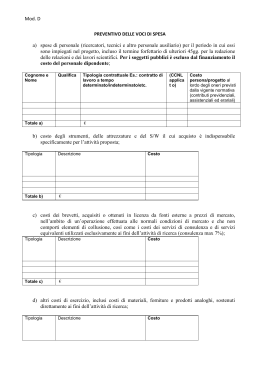
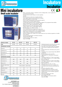
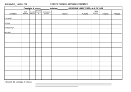
Scaricare