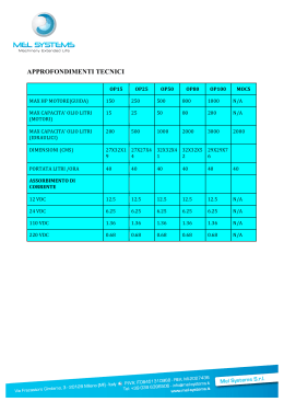
Strada Regina Km 3,5 • I 62018 Potenza Picena (MC) • Tel.0733/870.870 • Fax 0733/870.880 • http://www.audison.com
at 4 Ohms load with all channels in function.
- The amplifier power classification is made upon nominal 12 Volts battery voltage
- Continuous power given from RMS Voltage into resistive load
- Tolerance +10 %; -5 %
- 0.3 % THD
- 1 KHz or Cut off crossover frequency
- 12 VDC and 13.8 VDC
Power measures taken according to audison standard 1995 edition.
PRINTED IN ITALY - Cod. 10122300
Car power amplifier
Auto Hi Fi Endstufen
MANUAL D'ASSISTANCE
VR 404 XR
VR 404
Amplificateur de puissance pour l'automobile
Amplificatore di potenza per auto
SERVICE MANUAL
MANUALE DI SERVIZIO BEDIENUNGSANLEITUNG
2
AVVERTENZE
· INGRESSI: Nell'eventualità che il radioriproduttore non avesse in comune la massa di uscita
con il telaio si dovrà collegare la calza del cavo schermato con il telaio del radioriproduttore.
· USCITE: Non collegare in alcun caso tra loro oppure a massa le uscite -R e -L. Nel caso si
utilizzi un filtro crossover accertarsi che esso non abbia la massa in comune tra i canali.
· REGOLAZIONI: Nel caso si udissero fenomeni di saturazione a livelli di volume non
elevato, significa che il segnale esce distorto dal radioriproduttore. Portare il controllo di
volume del radioriproduttore verso un livello più basso fino alla scomparsa della distorsione.
Regolare successivamente i livelli di taratura dell'amplificatore fino ad udire lievi fenomeni
di saturazione.
INSTALLAZIONE
Il fissaggio si effettua mediante il serraggio nelle apposite sedi delle 4 viti e relativi distanziali
in dotazione. Per un'ottima riuscita dell'impianto si consiglia di usare i prodotti della linea
audison cable che comprendono: cavi di alimentazione, di segnale, per altoparlanti, connettori
RCA e tutti gli accessori per il completamento del cablaggio.
PRECAUZIONI
· Per un buon funzionamento dell'apparecchio è importante accertarsi che la temperatura nel
luogo dove esso è installato sia compresa tra 0°C e 55°C.
· Il luogo prescelto per l'installazione deve essere ben ventilato ed asciutto.
· La tensione di alimentazione è di 12 VCC con negativo a massa. Accertarsi che le
caratteristiche dell'impianto elettrico del veicolo siano adatte per questo apparecchio.
· Per una maggiore sicurezza di guida si consiglia l'ascolto ad un livello tale da non coprire
i suoni provenienti dall'esterno dell'auto.
CARATTERISTICHE
VR 404, VR 404XR. Amplificatori a 4 canali dalle elevate prestazioni acustiche. Ogni aspetto
funzionale, acustico ed estetico è stato ampiamente curato non fermandosi alle sole soluzioni
innovative ma utilizzando componentistica di elevata qualità, grazie alla cura “certosina” dei
particolari ed alla dotazione di funzioni accessorie per la massima praticità nell’uso.
L’alimentatore del tipo regolato PWM impiega transistors MOSFET che consentono una
notevole capacità di potenza senza cedimenti all’abbassarsi della tensione di batteria. Lo
stadio finale è configurato in ingresso con una coppia complementare di differenziali
polarizzati a corrente costante (a mezzo diodi LED) con evidenti vantaggi in termini di
stabilità e precisione timbrica.
Lo stadio di potenza è costituito da un TRIPLO DARLINGTON per la massima linearizzazione
della corrente di uscita con transitors finali capaci di sopportare correnti più elevate di quelle
normalmente richieste dall’utilizzo più gravoso.
Il VR 404 dispone di quattro ingressi PRE, di una uscita BY-PASS e di un filtro AMBIENT
EQUALIZER per l’espansione della scena acustica; le due coppie di canali possono lavorare
in MONO ed essere pilotate da due soli ingressi PRE.
Il VR 404XR dispone inoltre di un filtro crossover HI-PASS e uno LO-PASS (con fattore di
merito “Q” variabile) regolabili separatamente e non escludibili, con pendenza 12 dB/Ott.
Il Vostro amplificatore VR, per quanto finora detto, non potrà che fornirVi le migliori
emozioni nell’ascolto della musica e la audison Vi ringrazia per aver premiato il suo lavoro
sempre teso al raggiungimento dei massimi risultati.
ITALIANO
VR 404
VR 404
HI-PASS REAR
OUTPUT REAR
POWER INPUTS
L
INPUT
SUB
on off
INPUT
FRONT
control
REMOTE SUB LEVEL
off on
XR2F2
SUB
OUT
SUB
OUTPUT
SUBWOOFER
INPUT
REAR
off on
OUTPUT HI - PASS FRONT
OUTPUT HI - PASS REAR
R
OUT
FRONT
OUT
REAR
L
R
C
HI-PASS REAR
C
OUTPUT REAR
43
HI-PASS
FRONT
C
SUB
OUTPUT FRONT
HI-PASS
FRONT
C
FRONT SYSTEM (PASSIVE HI-PASS), REAR SYSTEM (PASSIVE HI-PASS) AND
SUBWOOFER WITH FADER OR WITHOUT FADER
HI-PASS FRONT
OUTPUT FRONT
rem mute
FRONT AND REAR SYSTEM (HI-PASS), SUBWOOFER (LO-PASS) WITH FADER AND
ELECTRONIC CROSSOVER
VR 404
VR 404
HI-PASS REAR
SUB
OUTPUT
HI-PASS
HI-PASS FRONT
C
HI-PASS REAR
C
42
OUTPUT REAR
SUB
OUTPUT FRONT
OUTPUT
HI-PASS
FRONT SYSTEM (HI-PASS), REAR SYSTEM (PASSIVE HI-PASS) AND SUBWOOFER
HI-PASS FRONT
OUTPUT FRONT
FRONT AND REAR SYSTEM (HI-PASS) AND SUBWOOFER (LO-PASS)
3
WARNING
· INPUTS: If the radio-cassette player doesn't share the output GND with the chassis, the
braided shield of the shielded cable must be connected to the radio-cassette player chassis.
· OUTPUTS: Never connect the -R and -L outputs to ground or to each other. If a crossover
filter is used be sure that its two channels don't have a common ground.
· REGULATIONS: If you hear distortion phenomena at moderate volume levels, it means that
a distorted signal is coming from the radio-cassette player. Turn radio-cassette player volume
down until there's no longer any distortion. Then adjust the calibration levels of the amplifier
until you hear slight saturation phenomena.
INSTALLATION
For mounting use 4 self-threading screws and protective plastic rings, provided. For a very
good result we suggest to use audison cable products to complete your installation. These
include: power cables, signal cables, speaker wires, RCA connectors and all accessories
needed to complete the wiring.
PRECAUTIONS
·In order for this device to function properly it's important that it is installed in a spot where
the temperature doesn't fall below 0°C or rise above 55°C.
· It must be installed in a dry and well ventilated spot.
· The power supply voltage is 12 VCC with negative to ground. Make sure that the
characteristics of the vehicle electrical system are compatible with this device.
· For safe driving we advise to listen to music at a volume level that won't drown external traffic
sounds.
FEATURES
VR 404, VR 404XR. 4 channels amplifiers with very high acoustic performances. Every
functional, acoustic and aesthetical aspect has been carefully taken into consideration by using
innovative solutions and high quality components, paying meticulous attention to details and
providing accessory functions which allow the maximum practicality. PWM controlled power
supply uses MOSFET transistors which allow a significant power capacity without slackening
when the battery voltage diminishes. The final stage in the input employs a complementary
couple of constant current polarised differentials (through LED diodes) with clearly
advantageous results in terms of stability and timbre precision. The power stage is made of a
TRIPLE DARLINGTON for the maximum output current linearization, with final transistors
able to bear higher currents than those which are normally required by the most demanding use.
VR 404 has four PRE inputs, a BY-PASS output and an AMBIENT EQUALIZER for the
acoustic front expansion; the two channels couples can work in MONO and they can be driven
by only two PRE inputs.
VR 404XR has also one HI-PASS and one LOW-PASS crossover filters (with a variable “Q”
factor) which can be adjusted separately and which can’t be disactivated, with 12dB/Oct.
slope.
Because of these features your VR amplifier can give you only the very best emotions in
listening to music. Audison thank you for rewarding their work which is always aimed at
reaching the very best results.
ENGLISH
4
WARNUNG:
· EINGANG: Falls das Massekabel des Autoradios nicht auf der Karosseriemasse liegt dann
muss das Masse-Kabel von der Endstufe auf das Autoradio-Chassis gelegt werden.
·AUSGANG: Nie den Ausgang auf gemeinsame Masse legen. Achten Sie darauf, das
passive Frequenzweichen nie eine gemeinsame Masse haben.
·ABSTIMMUNG: Bei der "gain" Abstimmung Empfehlen wir den Volume Regler des
Autoradios auf volle Lautstärke zu stellen und den Gain-Regler der Endstufe so weit zu
öffnen bis der Klang optimal eingestellt ist. Bei Auftreten von Verzerrungen kann es auch
am Autoradio liegen, bitte dann die Lautstärke (Volume) reduzieren (leiser stellen und den
Endstufen Empfindlichkeits regler (GAIN) einstellen.
EINBAU:
Für die Montage der Endstufen sind 4 Stk. Plastik Schutzplättchen für die Schrauben
vorgesehen. Zur Musikalischen Perfektion empfehlen wir, audison cable anzuwenden:
Power cable, Signal cable, LS cable, Chinch Stecker sowie Sicherungsblöcke samt Zubehör
für einen fachmännischen Einbau..
WICHTIGE HINWEISE:
· Der Einbauort soll trocken und Temperaturstabil sein (0°C - 55°C)
· Netzteil Voltage: 12 VCC negativ auf Masse. Darauf achten, dass die elektrische Anlage
des Wagens für diese Endstufe geeignet ist.
DIE EIGENSCHAFTEN:
VR 404, VR 404 XR. 4 Kanal Endstufen mit hervorragender, akustischen Eigenschaften. In
jeder Hinsicht funktionell, akustisch und ästhetisch. Dieses nicht nur durch eine neue
Konzeption, sondern durch Komponente von höchster Qualität. Dank des grossen
"Aufwandes", der Einzelheiten und Ausstattung des Zubehörs für einen praktischen Gebrauch.
Das Netzteil Typ PWM wendet MOSFET Transistoren an, die eine beachtenswerte
Kapazitätsstarke ohne Nach lassen der Batterie erlauben. Die Endstufe wird am Eingang
durch ein doppeltes komplementar Differenzial dargestellt, polarisiert durch konstantem
Strom (mittels LED-DIODEN) mit offentsichtlichem Vorteil für Stabilität und Musikalische
Präzision.
Die Endstufe besteht aus einer TRIPEL DARLINGTON für die höchste Linearität des
Ausgangsstroms mit Endtransistor, fähig einen höheren Strom zu leiten, als der, der normal
verbraucht wird.
Die VR 404 hat 4 PRE-EINGÄNGE zur Verfügung; ein BY-PASS Ausgang und einen
AMBIENT EQUALIZER Filter für ein akustisches Bühnenbild; die zwei Doppelkanale
können in Mono arbeiten und von nur zwei PRE-EINGÄNGEN gesteuert werden.
Die VR 404 XR besitzt auβerdem eine HI-PASS Weiche und eine LO-PASS (mit
veränderlichem "Q" Faktor) einzeln regulierbar und nicht ausschlieβbar, mit 12 dB per
oktave.
Die VR Verstärker, Ihnen nichts anderes vermitteln, als Sie beim Musikhören zu beeindrucken
und audison bedankt sich, daβ Sie ihre Arbeit, welche immer darauf aus ist, das Beste
Risultat zu erreichen, belohnen.
DEUTSCH
VR 404
L
R
INPUT
SUB
on off
INPUT
FRONT
INPUT
REAR
off on
OUTPUT
REAR
control
REMOTE SUB LEVEL
off on
XR2F2
OUT
SUB
OUT
FRONT
OUT
REAR
L
R
VR 404
HI-PASS FRONT
SUB STEREO
OR SUB MONO
HI-PASS FRONT
OUTPUT FRONT
POWER INPUTS
rem mute
L
R
41
SUB STEREO OR SUB MONO
INPUT
SUB
on off
INPUT
FRONT
HI-PASS REAR
OUTPUT SUBWOOFER
OUTPUT HI-PASS FRONT
OUTPUT REAR
INPUT
REAR
off on
control
OUT
SUB
OUT
FRONT
OUT
REAR
OUTPUT HI-PASS REAR
REMOTE SUB LEVEL
off on
XR2F2
R
L
FRONT AND REAR SYSTEM (HI-PASS), SUBWOOFER(LO-PASS) WITH FADER AND
ELECTRONIC CROSSOVER
POWER INPUTS
rem mute
OUTPUT
FRONT
OUTPUT HI-PASS FRONT
OUTPUT SUBWOOFER
FRONT SYSTEM (HI-PASS), REAR SUBWOOFER (LO-PASS) WITH FADER AND
ELECTRONIC CROSSOVER
VR 404 XR
SUB STEREO
OR
SUB MONO
OUTPUT HI-PASS
HI-PASS REAR
WOOFER FRONT
HI-PASS FRONT
OUTPUT
FRONT
WOOFER FRONT
40
OUTPUT BY-PASS
OUTPUT REAR
SUB STEREO
OR SUB MONO
HI-PASS REAR
FRONT SYSTEM (HI-PASS MID, TWEETER AND WOOFER), REAR SYSTEM (HI-PASS)
AND SUBWOOFER (LO-PASS) WITH FADER
HI-PASS
FRONT
OUTPUT
FRONT SYSTEM (HI-PASS), SUBWOOFER (LO-PASS)
AND REAR SYSTEM (WOOFER AND MID-HI)
VR 404 XR
ATTENTION
· ENTRÉES: Si la masse de sortie de l'autoradio n'est pas la même que celle du châssis, relier le
fil du câble isolant au châssis de l'auto-radio.
· SORTIES: Ne jamais connecter entre elles ou sur la masse les sorties -R et -L. Avant d'utiliser
un filtre crossover, s'assurer que les canaux n'ont pas de masse commune.
· RÉGLAGES: Si des phénomènes de saturation apparaissent à un niveau de volume modéré, cela
signifie que le signal sort distordu de l'auto-radio. En ce cas, abaisser le volume de l'auto-radio
jusqu'à ce que le phénoméne disparaisse et régler ensuite les niveaux de l'amplificateur.
5
INSTALLATION
Pour le montage utiliser les rondelles et vis fournies à cet effet. Pour un résultat optimum, il est
recommandé d'utiliser les éléments de la ligne audison cable suivants: câbles d'alimentation,
câbles signal, câbles pour haut-parleurs, connecteurs RCA et tous les accessoires complétant le
branchement.
PRÉCAUTIONS
· Pour un bon fonctionnement de l'appareil, il est très important de veiller à l'installer dans un
endroit où la température ne tombe jamais en dessous de 0° C et ne dépasse jamais 55° C.
· L'installation doit se faire dans un endroit sec et bien ventilé.
· L'alimentation est de type 12VCC avec négatif à la masse. S'assurer que les caractéristiques de
l'installation du véhicule soient adaptées à ce type d'appareil.
· Pour une conduite sans risque, nous conseillons un niveau d'écoute ne couvrant pas le bruit du
trafic environnant.
CARACTÉRISTIQUES
VR 404, VR 404XR. Amplificateurs à 4 canaux aux performances acoustiques très élevées.
Chaque aspect, qu'il soit fonctionnel, acoustique ou esthétique a fait l'objet de soins très
particuliers qui ne se limitent pas au seul choix de techniques innovatrices mais concernent
également l'emploi de matériaux de très bonne qualité, l'importance accordée aux moindres petits
détails et l'introduction de fonctions accessoires visant à faciliter au maximum l'utilisation des
appareils. L'alimentation de type PWM utilise des transistors MOSFET permettant d'obtenir une
grande puissance sans risque de fléchissements lorsque la batterie subit une baisse de voltage.
Le stade final est configuré à l'entrée par un couple complémentaire de différentiels polarisés à
courant constant (par des diodes LED), ce qui implique des avantages évidents en ce qui concerne
la stabilité et la précision du timbre.
Le stade de puissance est constitué d'un TRIPLE DARLINGTON pour une plus haute linéarisation
du courant de sortie, avec des transistors terminaux en mesure de supporter des courants
supérieurs aux courants normalement nécessaires à une utilisation plus intense.
Le VR 404 dispose de quatre entrées PRE, d'une sortie BY-PASS et d'un filtre AMBIENT
EQUALIZER pour l'expansion de l'aire acoustique; les deux couples de canaux peuvent travailler
en MONO et être pilotés depuis les deux seules entrées PRE.
En outre, le VR 404 XR dispose d'un filtre crossover HI-PASS et d'un filtre crossover LO-PASS
(avec coefficient de surtension variable), réglables séparément, non neutralisables, avec une
pente 12 dB/Oct. Ainsi, en conclusion de tout ce que vous venez de lire, soyez sûrs que, grâce à
votre amplificateur VR, l'écoute de la musique vous procurera une émotion intense...
Audison vous remercie de votre choix qui récompense ses efforts constants pout atteindre une
qualité toujours meilleure, une performance toujours plus poussée.
FRANÇAIS
6
8
8
16
LO PASS
SECTION
HI PASS
SECTION
MODE
5
mm2 AWG mm2 AWG
2 Ohms
UNIT FIXING
VR 404 / XR
Measure Unit
4 Ohms
4/5 m (13/16feet) length
SERVICE CONNECTION
Load
SIZE OF POWER CABLE
VR 404 - VR 404 XR
VR 203 - VR 206 - VR 209 - VR 404 - VR 404 XR
MUTE AND REMOTE MASTER SLAVE CONNECTION
VR 404 XR
VR 404 XR
SUB STEREO
OR
SUB MONO
OUTPUT BY-PASS
OUTPUT REAR
C
HI-PASS REAR
C
HI-PASS FRONT
OUTPUT FRONT
OUTPUT REAR
39
SUB STEREO
OR
SUB MONO
C
HI-PASS REAR
C
FRONT SYSTEM (HI-PASS), SUBWOOFER (LO-PASS) AND
REAR SYSTEM (PASSIVE HI-PASS) WITH FADER
HI-PASS FRONT
OUTPUT FRONT
FRONT SYSTEM (HI-PASS), REAR SYSTEM (HI-PASS) AND
SUBWOOFER (LO-PASS) WITH OR WITHOUT FADER
660
10.6
7.9
6.4
5.3
4.3
3.2
60
80
100
120
150
200
6.4
8.5
10.6
12.7
15.9
21.0
L mH
8 Ohms
38
FRONT SYSTEM (HI-PASS) AND SUBWOOFER (LO-PASS)
WITH OR WITHOUT FADER
VR 404 XR
200
265
330
400
495
C µF
4 Ohms
L mH
Hertz
FREQUENCY
LOUDSPEAKERS IMPEDANCE
100
132
165
200
245
330
C µF
VR 404
7
BLOCK DIAGRAM
8
35 W (RMS)
45 W (RMS)
65 W (RMS)
130 W (RMS)
0.04 %
3 Hz ÷ 75 KHz
140
4 µS
102 dBA
0.15 V ÷ 1.5 VRMS
15 KOhms
8; 4; 2 Ohms
8; 4 Ohms
0 dB
3 ÷ 15 VDC
12 VDC
3 ÷ 15 VDC
12 VDC
2-3-4
SELECTABLE (ON SELECTABLE (ON SELECTABLE (ON SELECTABLE
ON - OFF
(10.12 x 2.24 x 10.24
11 ÷ 15 VDC
1A
27 A
ENGLISH
TECHNICAL DATA
POWER SUPPLY
IDLING CURRENT
MAX ABSORPTION (Nominam Pwr)
CONT. NOMINAL POWER (Tol. +10%; -5%)
4 ch x 4 Ohms; 0.3% THD; 12 VDC
CONT. POWER (4 ch x 4 Ohms; 13.8 VDC)
CONT. POWER (4 ch x 2 Ohms; 13.8 VDC)
CONT. POWER (2 ch x 4 Ohms; 13.8 VDC) bridge
THD DISTORTION (1 KHz; 90% Nominal Pwr)
BANDWIDTH (-3 dB; Nominal Pwr)
DAMPING FACTOR (4 Ohms)
RISE TIME
SIGNAL / NOISE RATIO
INPUT SENSITIVITY
INPUT IMPEDANCE
LOAD IMPEDANCE stereo
mono
PREAMPLIFIED BY-PASS OUTPUTS GAIN
REMOTE IN
REMOTE OUT
MUTE IN
MUTE OUT
CHANNELS NUMBER
A MONO CHANNELS
B MONO CHANNELS
B MIXED MONO L + R CHANNELS
SINGLE/DUBLE STEREO INPUT
SELECTABLE AND ADJUSTABLE AMBIENT EQUALIZER
DIMENSIONS (WxHxD)
257 x 57 x 260 mm
VR 404
inch)
OFF)
OFF)
OFF)
35 W (RMS)
45 W (RMS)
65 W (RMS)
130 W (RMS)
0,04 %
3 Hz ÷ 75 KHz
140
4 µS
102 dBA
0,15 V ÷ 1,5 VRMS
15 KOhm
8; 4; 2 Ohm
8; 4 Ohm
0 dB
3 ÷ 15 VDC
12 VDC
3 ÷ 15 VDC
12 VDC
2-3-4
SELEZIONABILE (ON - OFF)
SELEZIONABILE (ON - OFF)
SELEZIONABILE (ON - OFF)
SELEZIONABILE
ON - OFF
257 x 57 x 260 mm
11 ÷ 15 VDC
1A
27 A
ITALIANO
DATI TECNICI
ALIMENTAZIONE
ASSORBIMENTO A VUOTO
ASSORBIMENTO MAX (Pot. Nominale)
POTENZA NOMINALE CONT. (Toll. +10%; -5%)
4 ch x 4 Ohm; 0,3% THD; 12 VDC
POTENZA CONTINUA (4 ch x 4 Ohm; 13,8 VDC)
POTENZA CONTINUA (4 ch x 2 Ohm; 13,8 VDC)
POTENZA CONTINUA (2 ch x 4 Ohm; 13,8 VDC)Bridge
DISTORSIONE THD (1 KHz; 90% Pot. nominale)
BANDA PASSANTE (-3 dB; Pot. nominale)
FATTORE DI SMORZAMENTO (4 Ohm)
TEMPO DI SALITA
RAPPORTO SEGNALE / RUMORE
SENSIBILITA' D'INGRESSO
IMPEDENZA D'INGRESSO
IMPEDENZA DI CARICO stereo
mono
GUADAGNO USCITE PREAMPLIFICATE BY-PASS
REMOTE IN
REMOTE OUT
MUTE IN
MUTE OUT
NUMERO CANALI
CANALI A MONO
CANALI B MONO
CANALI B MIXED MONO L + R
SINGOLO / DOPPIO INGRESSO STEREO
AMBIENT EQUALIZER VARIABILE E SELEZIONABILE
DIMENSIONI (BxAxL)
VR 404
OUT
Sortie destinée aux autres amplificateurs du système de reproduction.
Elle doit être connectée au
MUTE IN de l’amplificateur
suivant pour permettre la mise
en silence simultanée de tous les
amplificateurs connectés en
cascade. Le voltage disponible
sur cette sortie est de 12 VDC
avec un courant de 5 mA.
IN
Réglage d’activation
pour l’amplificateur
provenant de l’autoradio (ou de toute
autre source avec une
sortie pour le “remote” des amplificateurs).
Le voltage appliqué
doit être entre 3 et 15
VDC.
IN
Réglage d’entrée provenant de
l’autoradio (ou toute autre source
avec une sortie pour le “mute”
de l’amplificateur).
Il est spécialement destiné à étre
connecté à la sortie mute d’un
téléphone mobile. L’amplificateur est mis “sous silence” à
l’arrivée d’un appel; à la fin de
l’appel l’appareil réactive la reproduction musicale.
Il peut être connecté à la sortie
MUTE OUT de l’amplificateur
précédent pour obtenir une mise
en silence simultanée de tous les
amplificateurs connectés en
cascade. Le voltage doit être
entre 3 et 15 VDC.
37
OUT
Sortie destinée aux
autres amplificateurs
du système de reproduction.
Elle doit être connectée au REMOTE
IN de l’amplificateur
suivant pour permettre l’activation simultanée de tout le
système.
Le voltage disponible sur cette sortie est
de 12 VDC avec un
courant de 250 mA.
REMOTE
MUTE
POWER
Borne d’entrée pour
l’alimentation de
l’amplificateur.
Connecter le positif
et le négatif de la
batterie avec les
polarités indiquées.
Le voltage doit être
entre 11 et 15 VDC.
ON
Il indique que l’amplificateur
est
activé.
SAFE
Il indique l’ intervention des protections: surchauffe
(max 80 °C) ou anomalies de sortie
(présence d’un
courant continu,
court-circuit ou impédance de charge
très basse).
L’intervention des
protections rend
l’amplificateur
inopérant.
Mettre l’amplificateur en position
OFF, éliminer le
problème et remettre en position ON.
BORNES
D'ALIMENTATION
INDICATEURS
LUMINEUX
Tableau Postérieur
VR 404 - VR 404 XR
CONNEXIONS ET FONCTIONS
OUT
Sortie destinée aux autres amplificateurs du système de reproduction.
Elle doit être connectée au
MUTE IN de l’amplificateur
suivant pour permettre la mise
en silence simultanée de tous les
amplificateurs connectés en
cascade. Le voltage disponible
sur cette sortie est de 12 VDC
avec un courant de 5 mA.
IN
Réglage d’activation
pour l’amplificateur
provenant de l’autoradio (ou de toute
autre source avec une
sortie pour le “remote” des amplificateurs).
Le voltage appliqué
doit être entre 3 et 15
VDC.
IN
Réglage d’entrée provenant de
l’autoradio (ou toute autre source
avec une sortie pour le “mute”
de l’amplificateur).
Il est spécialement destiné à étre
connecté à la sortie mute d’un
téléphone mobile. L’amplificateur est mis “sous silence” à
l’arrivée d’un appel; à la fin de
l’appel l’appareil réactive la reproduction musicale.
Il peut être connecté à la sortie
MUTE OUT de l’amplificateur
précédent pour obtenir une mise
en silence simultanée de tous les
amplificateurs connectés en
cascade. Le voltage doit être
entre 3 et 15 VDC.
36
OUT
Sortie destinée aux
autres amplificateurs
du système de reproduction.
Elle doit être connectée au REMOTE
IN de l’amplificateur
suivant pour permettre l’activation simultanée de tout le
système.
Le voltage disponible sur cette sortie est
de 12 VDC avec un
courant de 250 mA.
REMOTE
MUTE
POWER
Borne d’entrée pour
l’alimentation de
l’amplificateur.
Connecter le positif
et le négatif de la
batterie avec les
polarités indiquées.
Le voltage doit être
entre 11 et 15 VDC.
ON
Il indique que l’amplificateur
est
activé.
SAFE
Il indique l’ intervention des protections: surchauffe
(max 80 °C) ou anomalies de sortie
(présence d’un
courant continu,
court-circuit ou impédance de charge
très basse).
L’intervention des
protections rend
l’amplificateur
inopérant.
Mettre l’amplificateur en position
OFF, éliminer le
problème et remettre en position ON.
BORNES
D'ALIMENTATION
INDICATEURS
LUMINEUX
Tableau Postérieur
VR 404 - VR 404 XR
CONNEXIONS ET FONCTIONS
FRANÇAIS
9
DONNÉES TECHNIQUES
ALIMENTATION
11 ÷ 15 VDC
CONSOMMATION MIN.
1A
CONSOMMATION MAX.
27 A
PUISSANCE NOMINAL CONTINUE (Toll. +10 %; -5 %)
4 ch x 4 Ohm; 0,3 % THD; 12 VDC
35 W (RMS)
PUISSANCE CONTINUE (4 ch x 4 Ohm; 13,8 VDC)
45 W (RMS)
PUISSANCE CONTINUE (4 ch x 2 Ohm; 13,8 VDC)
65 W (RMS)
PUISSANCE CONTINUE (2 ch x 4 Ohm; 13,8 VDC)
130 W (RMS)
DISTORSION HARM. TOTALE (1 KHz; 90 % Puiss. Nom.)
0,04 %
BANDE PASSANTE (-3 dB; Puiss. Nom.)
3 Hz ÷ 75 KHz
COEFFICIENT D'AMORTISSEMENT (4 Ohm)
140
TEMPS DE MONTÉE
4 µS
RAPPORT SIGNAL/BRUIT
102 dBA
SENSIBILITÉ D'ENTRÉE
0,15 V ÷ 1,5 VRMS
IMPEDANCE D'ENTRÉE
15 KOhm
IMPEDANCE DE CHARGE stereo
8; 4; 2 Ohm
mono
8; 4 Ohm
GAIN DES SORTIES BY-PASS PRÉAMPLIFIÉES
0 dB
REMOTE IN
3 ÷ 15 VDC
REMOTE OUT
12 VDC
MUTE IN
3 ÷ 15 VDC
MUTE OUT
12 VDC
NOMBRE DE CANAUX
2-3-4
CANAUX A MONO
SÉLECTIONNABLE (ON - OFF)
CANAUX B MONO
SÉLECTIONNABLE (ON - OFF)
CANAUX B MIXED MONO L + R
SÉLECTIONNABLE (ON - OFF)
ENTRÉE STEREO UNIQUE/DOUBLE
SÉLECTIONNABLE
AMBIENT EQUALIZER VARIABLE ET SÉLECTIONNABLE ON - OFF
DIMENSIONS (BxHxL)
257 x 57 x 260 mm
VR 404
35 W (RMS)
45 W (RMS)
65 W (RMS)
130 W (RMS)
0,04 %
3 Hz ÷ 75 KHz
140
4 µS
102 dBA
0,15 V ÷ 1,5 VRMS
15 KOhm
8; 4; 2 Ohm
8; 4 Ohm
0 dB
3 ÷ 15 VDC
12 VDC
3 ÷ 15 VDC
12 VDC
2-3-4
VERÄNDLICHER (ON - OFF)
VERÄNDLICHER (ON - OFF)
VERÄNDLICHER (ON - OFF)
VERÄNDLICHER
ON - OFF
257 x 57 x 260 mm
11 ÷ 15 VDC
1A
27 A
DEUTSCH
TECHNISCHE DATEN
BETRIEBSSPANNUNG
STROMAUFNAHME MIN
STROMAUFNAHME MAX (Nominal Leistung)
NOMINAL LEISTUNG (Tol. +10 %; -5 %)
4 ch x 4 Ohm; 0,3 % THD; 12 VDC
LIN. LEISTUNG (4 ch x 4 Ohm; 13,8 VDC)
LIN. LEISTUNG (4 ch x 2 Ohm; 13,8 VDC)
LIN. LEISTUNG MONO (2 ch x 4 Ohm; 13,8 VDC)
VERZERRUNGEN THD (1 KHz; 90 % Nominal Leistung)
FREQUENZBEREICH (-3 dB; Nominal Leistung)
DÄMPFUNGSFAKTOR (4 Ohm)
ANSTIEGSZEIT
RAUSCHSPANNUNGSABSTAND
EINGANGSEMPFINDLICHKEIT
EINGANGSIMPEDANZ
BELASTUNGSIMPEDANZ stereo
mono
BY-PASS AUSGANGSWERT
REMOTE IN
REMOTE OUT
MUTE IN
MUTE OUT
KANAL ANZAHL
KANAL A MONO
KANAL B MONO
KANAL B MONO L + R
EINZELNER/DOPPELTER STEREOEINGÄNGE
REGELBARER AMBIENTE EQUALIZER
ABMESSUNGEN (BxHxT)
VR 404
VR 404
10
H• Selettore per utilizzare due o quattro ingressi.
Posizione IN A IN B (quattro ingressi)
Permette di pilotare i canali A con l'ingresso preamplificato IN A e di pilotare i canali
B con l'ingresso preamplificato IN B.
Posizione IN A+B (due ingressi)
Permette di pilotare i canali A ed i canali B con l'ingresso preamplificato INA.
MODE ( H )
E• Selettore per attivare (ON) o escludere (OFF) l'azione del filtro AMBIENT EQUALI
ZER.
G• Controllo di livello che regola l'intensità di azione del filtro stesso. Agisce sulle uscite
preamplificate OUT BY-PASS, sulle uscite di potenza dei canali A e sulle uscite di
potenza dei canali B, nel caso in cui gli ingressi dell'amplificatore siano selezionati
come IN A+B (MODE SECTION - H).
AMBIENT EQUALIZER (E-G)
B• LEVELS: Regolatore di livello Left e Right dei canali B. La sensibilità varia da 0,15
a 1,5 Volt.
D• MONO IN R: Seleziona le uscite Left e Right in stereo (OFF) o mono (ON). L'ingresso
IN A - IN B o IN B abilitato mono per la configurazione a ponte (BRIDGE) è il Right.
F• MIXED MONO (L + R): Sulla posizione ON somma in mono gli ingressi Left e Right
(IN A - IN B o IN B) dei canali B. Il collegamento delle uscite di potenza permette di
scegliere la configurazione mono due canali oppure mono in BRIDGE indispensabile
in caso di unico Subwoofer.
SECTION "B" (B-D-F) Canale Sinistro (Left) e Destro (Right) della sezione B.
A• LEVELS: Regolatore di livello Left e Right dei canali A. La sensibilità varia da 0,15
a 1,5 Volt.
C• MONO IN R: Seleziona le uscite Left e Right in stereo (OFF) o mono (ON). L'ingresso
IN A - IN B o IN B abilitato mono per la configurazione a ponte (BRIDGE) è il Right.
SECTION "A" (A-C) Canale Sinistro (Left) e Destro (Right) della sezione A.
CONTROLLI SUPERIORI
OUT
Verbinden Sie diesen
Anschluss mit dem Mute in
Anschluss einer eventuell
weiteren Endstufe zur automatischen Stummschaltung.
Die Ausgangsspannung dieses Anschlusses beträgt 3
und 15 VDC. Der Ausgang
ist bis 5 mA belastbar.
IN
Verbinden Sie diesen Anschluss mit dem Anschluss
Ihres Autotelefons zur automatischen Stummschaltung
von Endverstärker.
ACHTUNG: Dieser muβ eine
positive Schaltspannung von
3 - 15 VDC Befern.
Bei
Eingang
eines
Telefongespräches wird der
Verstärker automatisch
stummgeschaltet bzw, nach
Beendigung des Gespräches
wird die vormals eingestellte
Lautstärke wieder hergestellt.
MUTE
35
OUT
Verbinden Sie diesen Anschluss mit dem Remote
Eingang eines eventuell
weiteren Endverstärkers.
Der Anschluss soll den
Schaltspannungs-ausgang
ihres
Steuergerätes
entlasten, sowie für eine
einfachere Verkabelung
sorgen Die Ausgangsspannung beträgt 12 VDC
und ist belastbar bis 250
mA.
IN
Verbinden Sie diesen
Anschluss mit dem
Anschluss
Ihres
Steuergerätes zur automatischen Einschaltung von
Endverstärker.
Dieser ist in der Regel,
wenn nicht gesondert
gekennzeichnet, der
e l e k t r o n i s c h e
Antennenanschluss Der
Endverstärker arbeitet bei
einer Einschaltspannung
von 3 - 15 VDC.
REMOTE
Hinterteil
SAFE
Die
rote
LED
signalisiert
eine
Störung Die Schutzschaltung reagiert auf
Uberhitzung (80°)
Kurzschluβ an den
Lautsprecherausgängen,
hohe Verzerrungen
oder auf einen
internen
Fehler.
Schalten Sie die
Endstufe aus und nach
einer Abkühlphase
erneut wieder ein
leuchtet die rote LED
immer noch, setzen
Sie sich mit ihren
Fachhändler
in
Verbindung.
ON
Die grüne LED
signalisiert
den
Betriebszustand.
FUNKTIONSANZEIGEN
VR 404 - VR 404 XR
ANSCHLÜSSE UND FUNKTIONEN
POWER
Verbinden Sie den
Plusanschluβ über
die beigefügte
Sicherung direkt
mit dem Plusanschluβ
ihrer
Autobatterie. Den
Minusanschlu β
verbinden Sie mit
der Fahrzeugmasse.
Beachten
Sie
Betriebs spannung
von 11 - 15 VDC
mit
negativer
Μasse.
Sorgen Sie für
einen
festen
Kontakt der Kabel.
VERSORGUNGSANSCHLÜSSE
HI-PASS
SPEAKERS
Ausgang der
HI-PASS
Stärke Links
und Rechts.
Das Signal
ist dem Filter HI-PASS
(ausschlieβlich)
und
dem
Ambient
Equalizer
unterworfen.
Die Grenzfrequenz ist
auf
zwei
Ebenen von
40 Hz bis
800 Hz an
der Oberseite des Geräts
regulierbar.
AUSGANGSANSCHLÜSSE
IN
Haupteingang
Links und Rechts
des Verstärkers.
Er reguliert die zwei
HI-PASS Kanäle
des Verstärkers und
kann auch die zwei
L O - P A S S
regulieren wenn
man die ModeTaste (auf der
Vorderseite) mit
OUT HI wählt.
In diesem Fall
erhalten wir den HIPASS AUSGANG
mit IN LO - OUT
HI benannt.Die
Anschlüsse müssen
am Ausgang des
Vorverstärker
angebracht werden
wie z.B. ein Autoradio, ein CD
Spieler,
ein
elektronischer crossover.
HAUPTEINGANG
34
OUT
BY-PASS
Anschluss des
By-Pass an den
Vorverstärker.
Das
Signal
befindet sich
unter dem Ambient Equalizer
F i l t e r
(ausschlieβlich)
welcher das
Hauptsignal IN
auffängt.
Sie sind für
einen weiteren
Verstärker oder
elektronischen
crossover oder
a n d e r e
Einrichtungen
für Tonabgabe
bestimmt.
AUSGANG
BY-PASS
Vorderteil
IN LO
OUT HI
Die Verbindung
RCA sind für
das Ein-oder
Ausgangssignal
bestimmt.
Man kann es
durch
die
Funktion des
M O D E SELEKTORS
wählen.
E i n g a n g :
Steuergerät der
L O - P A S S
Selektion; in
diesem
Fall
stellen Sie die
Mode-Taste auf
IN LO.
Ausgang: HIPASS;
in
diesem
Fall
stellen Sie die
MODE-TASTE
auf OUT HI.
Die 4 Kanäle
werden
vom
Eingang
IN
gesteuert.
MONO
Ausgang ( L- und R+)
zur Verbindung des
Subwoofer mono wenn
er von MIXED MONO
BRIDGE angesteuert
wird (Summe der
Kanäle)
mittels
Selektor auf der Oberseite des Geräts.
LO-PASS
SPEAKERS
Ausgang
der
Lautsprecher LOPASS links und rechts.
Das Vorhandene Signal unterliegt dem
LO PASS FILTER
(ausschlieβlich)
welche den FAKTOR
"Q" mit inbegriffen
haben und ändert sich
von 0,7 bis 3 (Flanken
steilheit des LO-PASS
Filters, Typ Butterworth, er erlaubt den
Nachdruck des Signals
bei crossover frequenz).
Die Grenzfrequenz ist
auf zwei Ebenen von
40 Hz bis 800 Hz an
der Oberseite des
Geräts regulierbar.
LO-PASS EINGANG
AUSGANGSANSCHLÜSSE
HI-PASS AUSGANG
VR 404 XR
ANSCHLÜSSE UND FUNKTIONEN
LO PASS
SECTION
MODE
11
H• Switch to select two or four inputs.
IN A IN B position (four inputs):
It allows to drive A channels with the IN A preamplified input and to drive B channels
with the IN B preamplified input.
IN A+B position (two inputs):
It allows to drive A channels and B channels with IN A preamplified input.
MODE ( H )
if the amplifier inputs are selected as IN A+B (MODE SECTION - H).
E• Switch which activates (ON) or disactivates (OFF) the AMBIENT EQUALIZER filter.
G• Level control which controls the feedback intensity. It acts on OUT BY-PASS
preamplified outputs, on A channels power outputs and on B channels power outputs
AMBIENT EQUALIZER (E-G)
only one Subwoofer.
B• LEVELS: Left and Right level control of B channels. Sensitivity is between 0.15 to
1.5 Volts.
D• MONO IN R:It selects Left and Right outputs in stereo (OFF) or mono (ON). IN A IN B mono input for bridge configuration is the Right one.
F• MIXED MONO (L + R): In ON position, it mixes Left and Right inputs (IN A - IN B)
of B channels. The type of power output connection allows to choose the mono two
channels configuration or mono in BRIDGE configuration, necessary in case there is
SECTION "B" (B-D-F) Left and Right channel of B section.
IN B mono input for bridge configuration is the Right one.
A• LEVELS: Left and Right level control of A channels. Sensitivity is between 0.15 to
1.5 Volts.
C• MONO IN R: It selects Left and Right outputs in stereo (OFF) or mono (ON). IN A -
SECTION "A" (A-C) Left and Right channel of A section.
HI PASS
SECTION
UPPER CONTROLS
VR 404
12
H• Regler für zwei oder vier Eingänge.
Position IN A IN B (vier Eingänge) Erlaubt die Steuerung von Kanal A mit den
Vorstufeneingang IN A und den Kanale B mit den Vorstufeneingang IN B.
Position IN A+B (zwei Eingänge) Erlaubt die Steuerung von Kanal A und Kanal B mit
Vorstufeneingang IN A.
MODE ( H )
E• Regler zur Aktivierung (ON) oder Disaktivierung (OFF) des AMBIENT EQUALIZER
Filter.
G• Der Regler reguliert das Aktionsfeld des Filters. Er wirkt auf die Vorstufe OUT BYPASS, auf die Ausgange von Kanal A und auf die Ausgänge von Kanale B, wenn die
Verstärkereingänge wie IN A+B selektiert sind (MODE SECTION - H) ein.
AMBIENT EQUALIZER (E-G)
B• LEVELS: Empfindlichkeitsregler Links und Rechts von Kanäle B. Die Empfindlichkeit
wechselt von 0,15 bis 1,5 V.
D. MONO IN R: Selektiert die Linken und Rechten Ausgänge in stereo (OFF) oder mono
(ON). Bitte den Rechten Mono Eingang IN A - IN B oder IN B für BRIDGE
verwenden.
F• MIXED MONO (L+R): Auf der Position ON werden die linken und rechten Eingänge
(IN A - IN B oder IN B) der Kanäle B zusammen gezogen. Der Typ der Verbindung
der Ausgänge erlauben die Darstellung Mono zwei Kanäle oder mono in BRIDGE zu
wählen, wenn nötig nur ein Subwoofer besteht.
SECTION "B" (B-D-F) Linker (Left) und Rechter (Right) Kanal der B Sektion
A• LEVELS: Empfindlichkeitsregler Links und Rechts von Kanäle A. Die Empfindlichkeit
wechselt von 0,15 bis 1,5 V.
C• MONO IN R: Selektiert die Linken und Rechten Ausgänge in stereo (OFF) oder mono
(ON). Bitte den Rechten Mono Eingang IN A - IN B oder IN B für BRIDGE
verwenden.
SECTION "A" (A-C) Linker (Left) und Rechter (Right) Kanal der A Sektion
OBERE REGLER
OUT
Output for the other amplifiers in
sound system.
It must be connected to the
MUTE IN of the successive
amplifier to allow the
simultaneous silencing of all
amplifiers connected in cascade.
The available voltage on this output is 12 VDC with current equal
to 5 mA.
IN
Turn on control for
the amplifier coming
from radio/cassette
player (or from any
source provided with
remote control for
amplifiers).
The applied voltage
must be between 3
and 15 VDC.
IN
Mute control coming from radio/cassette player (or any source
provided with output for the amplifier mute).
It is especially made to be
connected to the mute output of a
cellular telephone in order to
silence the amplifier for incoming
calls, and it allows to reactivate
musical reproduction at the end
of phone conversation.
It can be connected to the MUTE
OUT output of a preceding amplifier to allow the simultaneous
silencing of all amplifiers
connected in cascade.
The applied voltage must be
between 3 and 15 VDC.
33
OUT
Output leading to
other amplifiers of the
sound system.
It has to be connected
to the REMOTE IN
of
successive
amplifiers to allow
the simultaneous
turning on of the
whole system.
The available voltage
on this output is 12
VDC with a current
equal to 250 mA.
REMOTE
MUTE
Rear Side
POWER
Input clamps for the
amplifier power supply.
Connect the battery
positive and negative according to the
indicated polarities.
The applied voltage
must be between
11 and 15 VDC.
ON
Lit when amplifier
is ON.
SAFE
When lit it indicates
the intervention of
protection circuits:
in
case
of
overheating (temperature exceeding 80°
C /176° F) or output
anomalies (presence
of continuous current, short circuit, or
dangerously low
load impedance).
When protection
cir-cuits intervene
the amplifier shuts
down. Turn the amplifier off.
When the problem
is corrected turn the
amplifier back on.
POWER SUPPLY
CLAMPS
INDICATORS
LIGHTS
VR 404 - VR 404 XR
CONNECTIONS AND FUNCTIONS
HI-PASS
SPEAKERS
Left and rigth
HI-PASS
power outputs.
The available
signal is subjected to the
action of the
HI-PASS filter (which
can't
be
exclued) and
of the AMB I E N T
EQUALIZER filter.
The cut off
frequency
can be adjusted in two
ranger from
40 Hz to 800
Hz through
special controls put on
the
upper
part of the
amplifier.
OUTPUT
CLAMPS
IN
Left and right inputs
of the amplifier. It
drives directly the
two HI-PASS channels of the amplifier
and it can also drive
the two LO-PASS
channels when the
MODE button (on
the upper part) is
selected as OUT HI.
In this case the HIPASS preamplified
output is available;
it is called IN LO OUT HI.
Connections have to
be made from the
preamplified output
of a source, for
example a radio cassette player, a CD
player, an electronic
crossover or any
devices
which
handle the musical
signal
at
a
preamplified stage.
GENERAL INPUT
32
OUT
BY-PASS
Preamplified
BY-PASS outputs of the
amplifier.
The available
signal is subjected to the
action of the
AMBIENT
EQUALIZER
filter (which
can be activated or not)
which handles
the
signal
coming from
the IN general
input.
They are for
another amplifier,
an
electronic
crossover or
any devices
which handle
the musical signal at a preamplifier
stage.
BY-PASS
OUTPUTS
Front Side
IN LO
OUT HI
RCA
connectors which
can be used as
signal input or
output.
They can be selected through
the special function handled
by the MODE
switch.
Input to drive
the LO-PASS
section of the
device, in this
case the MODE
switch has to be
put on IN LO
position.
HI-PASS output, in this case
the
MODE
switch has to be
put on OUT HI
position; the
four channels of
the amplifier
are driver by the
IN input.
LO-PASS INPUTS
HI-PASS OUTPUTS
MONO
Power outputs ( L- and
R+). They have to be
used to connect a mono
subwoofer when the
MIXED MONO BRIDGE (sum of the channels)
is actived through the
special switches put on
the upper part of the
device.
LO-PASS SPEAKERS
Left and rigth LO-PASS
power outputs.
The available signal is
subjected to the action
of the LO-PASS filter
(which
can't
be
excluded) includes the
adjustment of the Q
factor.
This varies from 0,7 (cut
slope of the butterworth
LO-PASS filter) to 3 (it
increases the signal by
the set crossover frequency).
The cut-off frequency
can be adjusted in two
ranger from 40 Hz to 800
Hz through special controls put on the upper
part of the amplifier.
OUTPUT CLAMPS
VR 404 XR
CONNECTIONS AND FUNCTIONS
LO PASS
SECTION
MODE
13
H• Sélecteur pour l'utilisation de deux ou de quatre entrées.
Position IN A IN B (quatre entrées) Elle permet de piloter les canaux A avec l'entrée
préamplifiée IN A et de piloter les canaux B avec l'entrée préamplifiée IN B.
Position IN A+B (deux entrées) Elle permet de piloter les canaux A et les canaux B avec
l'entrée préamplifiée IN A.
MODE ( H )
E• Sélecteur pour mettre en fonction (ON) ou neutraliser (OFF) le filtre AMBIENT
EQUALIZER.
G• Contrôle de niveau qui règle l'intensité d'action du filtre lui-même. Il agit sur les sorties
préamplifiées OUT BY-PASS, sur les sorties de puissance des canaux A et sur les
sorties de puissance des canaux B lorsque les entrées de l'amplificateur sont sélectionnées
en IN A+B (MODE SECTION - H).
AMBIENT EQUALIZER (E-G)
B• LEVELS: Réglage de niveau Right - Left des canaux B. La sensibilité est entre 0,15 et
1,5 Volts.
D• MONO IN R: Sélectionne les sorties Right et Left en stéréo (OFF) ou mono (ON).
L'entrée mono IN A - IN B ou IN B pour la configuration à pont (BRIDGE) est Right.
F• MIXED MONO (L+R):En ON, il mélange les entrées Left et Right (IN A - IN B ou IN
B), des canaux B en mono. La sorte de connexion des sorties de puissance permet de
choisir la configuration mono deux canaux ou mono en BRIDGE, nécessaire quandil
y a seulement un Subwoofer.
SECTION "B" (B-D-F) Canal Gauche (Left) et Droit (Right) de la section B.
A• LEVELS: Réglage de niveau Left - Right des canaux A. La sensibilité est entre 0,15
et 1,5 Volts.
C• MONO IN R: Sélectionne les sorties Left et Right en stéréo (OFF) ou mono (ON).
L'entrée mono IN A - IN B ou IN B pour la configuration à pont (BRIDGE) est Right.
SECTION "A" (A-C) Canal Gauche (Left) et Droit (Right) de la section A.
HI PASS
SECTION
RÉGLAGES SUPÉRIEURS
14
OUT BYPASS
Uscite BYPASS preamplificate dell'amplificatore.
Il segnale disponibile è
sottoposto all'azione del
filtro AMB I E N T
EQUALIZER
(attivabile o
meno)
che
tratta il segnale derivato
dall'ingresso
generale IN.
Sono destinate ad un ulteriore amplificatore o crossover elettronico o un qualunque dispositivo per il
trattamento
del segnale
musicale a livello preamplificato.
IN A
IN A + B
Ingressi left e rigth
dell'amplificatore.
Pilota direttamente i due canali A
dell'amplificatore
e può pilotare anche i due canali B
qualora il pulsante
MODE (posto sulla parte superiore)
venga selezionato
come IN A + B.
Le connessioni
vanno effettuate
verso
l'uscita
preamplificata della sorgente, ad
esempio un'autoradio, un lettore CD,
un crossover elettronico o un qualunque dispositivo
per il trattamento
del segnale musicale a livello
preamplificato.
A SPEAKERS
Uscite di potenza left e
rigth dei canali
A.
Il segnale disponibile è sottoposto
all ' a z i o n e
dell'AMBIENT
EQUALIZER
regolabile per
mezzo di appositi controlli
posizionati
sulla parte superiore dell'amplificatore.
MONO
Uscite di potenza (+L e -R)
da utilizzare
per collegare
un altoparlante
mono, qualora
venga attivata
la funzione
MONO IN R
per mezzo dell'apposito
selettore posto
sulla parte superiore dell'apparecchio.
USCITE
BY-PASS
INGRESSO
GENERALE
IN B
Ingressi left e
rigth dell'amplificatore.
Sono attivabili per mezzo del selettore MODE
(sulla parte
superiore
dell'amplificatore) posto
nella posizione IN A - IN
B.
INGRESSI B
MONO
Uscite di potenza (L- e
R+) da utilizzare per collegare un altoparlante
mono, qualora venga attivata la funzione MONO
IN R (ingresso abilitato
rigth) oppure MIXED
MONO L + R (somma
dei canali), per mezzo
degli appositi selettori
posti sulla parte superiore dell'apparecchio.
B SPEAKERS
Uscite di potenza left e
rigth dei canali B.
Il segnale disponibile è
sottoposto all'azione dell'AMBIENT EQUALIZER (regolabile per mezzo di appositi controlli
posizionati sulla parte superiore dell'amplificatore) nel caso in cui i canali
A e B siano gestiti dall'ingresso generale IN
nella configurazione
MODE IN A + B.
Se i canali B sono pilotati dal solo ingresso B,
queste uscite di potenza
vengono private dell'azione del filtro AMBIENT EQUALIZER.
MORSETTI DI
USCITA Ch B
OUT
Uscita destinata agli altri amplificatori dell'impianto di riproduzione. Va collegata al
MUTE IN dell'amplificatore
successivo per consentire il
silenziamento contemporaneo di tutti gli amplificatori
connessi in cascata. La tensione disponibile su questa
uscita è di 12 VDC con una
corrente pari a 5 mA.
IN
Comando d'ingresso proveniente dall'autoradio (o qualunque tipo di sorgente provvista di apposita uscita per il
mute dell'amplificatore).
E' destinato in particolare per
essere collegato all'uscita
mute di un telefono cellulare
per silenziare l'amplificatore
all'arrivo di una chiamata; al
termine della conversazione
l'apparecchio riattiva la riproduzione musicale.
Il collegamento può essere effettuato con l'uscita MUTE
OUT dell'amplificatore precedente per consentire il
silenziamento contemporaneo di tutti gli amplificatori
connessi in cascata. La tensione applicata deve essere
compresa fra 3 e 15 VDC.
MUTE
31
OUT
Uscita destinata
agli altri amplificatori dell'impianto
di riproduzione.
Va collegata al REMOTE IN dell'amplificatore successivo per consentire
l'accensione simultanea di tutto l'impianto.
La tensione disponibile su questa
uscita è di 12 VDC
con una corrente
pari a 250 mA.
IN
Comando di accensione per l'amplificatore proveniente
dall'autoradio (o
qualunque tipo di
sorgente, provvista
di apposita uscita
per il comando di
remote per gli amplificatori).
La tensione applicata deve essere
compresa fra 3 e 15
VDC.
REMOTE
SAFE
Indica l'intervento
delle protezioni:
temperatura eccessiva (80°C max) o anomalie di uscita (presenza di corrente
continua, cortocircuito o impedenza
del carico pericolosamente bassa).
L'intervento della
protezione rende
inoperativo l'amplificatore.
Spegnere l'amplificatore, rimuovere la
causa dell'anomalia
e quindi riaccendere
l'apparecchio.
ON
Indica l'accensione
dell'amplificatore.
SEGNALAZIONI
LUMINOSE
Pannello Posteriore
Pannello Anteriore
MORSETTI DI
USCITA Ch A
VR 404 - VR 404 XR
COLLEGAMENTI E FUNZIONI
VR 404
COLLEGAMENTI E FUNZIONI
POWER
Morsetti di ingresso per l'alimentazione dell'amplificatore.
Collegare il positivo ed il negativo
di batteria con le
polarità indicate.
La tensione applicata deve essere
compresa tra 11 e
15 VDC.
MORSETTI DI
ALIMENTAZIONE
INGRESSO
GENERALE
IN
Ingressi LEFT e RIGHT dell'amplificatore.
Pilota direttamente i
due canali HI-PASS
dell'amplificatore e
può pilotare anche i
due canali LO-PASS
qualora il pulsante
MODE (posto sulla
parte superiore) venga selezionato come
OUT HI.
In questo caso è disponibile l'uscita
preamplificata HIPASS nominata IN
LO - OUT HI.
Le connessioni vanno effettuate verso
l'uscita preamplificata della sorgente,
ad esempio un'autoradio, un lettore CD,
un crossover elettronico o un qualunque
dispositivo per il
trattamento del segnale musicale a livello preamplificato.
HI-PASS
SPEAKERS
Uscite di potenza HIPASS left e
right.
Il segnale disponibile è
sottoposto
all'azione
del filtro HIPASS (non
escludibile)
e dell'AMB I E N T
EQUALIZER.
La frequenza
di taglio è
regolabile in
due gamme,
da 40 Hz a
800 Hz, per
mezzo degli
appositi controlli posizionati sulla
parte superiore dell'amplificatore.
30
OUT
BY-PASS
Uscite BYPASS preamplificate dell'amplificatore.
Il segnale disponibile è
sottoposto all'azione del
filtro AMB I E N T
EQUALIZER
(attivabile o
meno)
che
tratta il segnale derivato
dall'ingresso
generale IN.
Sono destinate ad un ulteriore amplificatore o crossover elettronico o un qualunque dispositivo per il
trattamento
del segnale
musicale a livello preamplificato.
USCITE
BY-PASS
IN LO
OUT HI
Connettori RCA
utilizzabili
come ingresso o
come uscita di
segnale.
Sono configurabili per mezzo
della funzione
impostata dal
s e l e t t o r e
MODE.
Ingresso per pilotare la sezione LO-PASS
dell'apparecchio; in questo
caso il pulsante
MODE va posizionato su IN
LO.
Uscita
HIPASS; in questo
caso il pulsante
MODE va posizionato su OUT
HI e i quattro
canali dell'amplificatore vengono pilotati
dall'ingresso
IN.
INGRESSI LO-PASS
USCITE HI-PASS
IN
Comando di accensione per l'amplificatore proveniente
dall'autoradio (o
qualunque tipo di
sorgente, provvista
di apposita uscita
per il comando di
remote per gli amplificatori).
La tensione applicata deve essere
compresa fra 3 e 15
VDC.
IN
Comando d'ingresso proveniente dall'autoradio (o qualunque tipo di sorgente provvista di apposita uscita per il
mute dell'amplificatore).
E' destinato in particolare per
essere collegato all'uscita
mute di un telefono cellulare
per silenziare l'amplificatore
all'arrivo di una chiamata; al
termine della conversazione
l'apparecchio riattiva la riproduzione musicale.
Il collegamento può essere effettuato con l'uscita MUTE
OUT dell'amplificatore precedente per consentire il
silenziamento contemporaneo di tutti gli amplificatori
connessi in cascata. La tensione applicata deve essere
compresa fra 3 e 15 VDC.
OUT
Uscita destinata agli altri amplificatori dell'impianto di
riproduzione. Va collegata al
MUTE IN dell'amplificatore
successivo per consentire il
silenziamento contemporaneo di tutti gli amplificatori
connessi in cascata. La tensione disponibile su questa
uscita è di 12 VDC con una
corrente pari a 5 mA.
LO-PASS SPEAKERS
Uscite di potenza LOPASS left e right.
Il segnale disponibile è
sottoposto all'azione del
filtro LO-PASS (non
escludibile) che comprende la regolazione del
Fattore di merito "Q" variabile da 0,7 (pendenza
di taglio del filtro LOPASS di tipo Butterworth) a 3 (conferisce un'enfasi del segnale nei pressi della frequenza di
crossover impostata).
La frequenza di taglio è
regolabile in due gamme
da 40 Hz a 800 Hz per
mezzo degli appositi
controlli sulla parte superiore dell'apparecchio.
MONO
Uscite di potenza (L- e
R+) da utilizzare per collegare un subwoofer
mono, qualora venga attivata la funzione MIXED
MONO BRIDGE (somma dei canali), per mezzo
dell'apposito selettore posto sulla parte superiore
dell'apparecchio.
15
OUT
Uscita destinata
agli altri amplificatori dell'impianto
di riproduzione.
Va collegata al REMOTE IN dell'amplificatore successivo per consentire
l'accensione simultanea di tutto l'impianto.
La tensione disponibile su questa
uscita è di 12 VDC
con una corrente
pari a 250 mA.
REMOTE
MUTE
MORSETTI DI
USCITA
SAFE
Indica l'intervento
delle protezioni:
temperatura eccessiva
(80°C
max) o anomalie
di uscita (presenza di corrente continua, cortocircuito o impedenza del carico pericolosamente bassa).
L'intervento della
protezione rende
inoperativo l'amplificatore.
Spegnere l'amplificatore, rimuovere la causa dell'anomalia e quindi riaccendere
l'apparecchio.
ON
Indica l'accensione dell'amplificatore.
SEGNALAZIONI
LUMINOSE
Pannello Posteriore
Pannello Anteriore
MORSETTI
DI USCITA
VR 404 - VR 404 XR
COLLEGAMENTI E FUNZIONI
VR 404 XR
COLLEGAMENTI E FUNZIONI
POWER
Morsetti di ingresso per l'alimentazione dell'amplificatore.
Collegare il positivo ed il negativo di
batteria con le
polarità indicate.
La tensione applicata deve essere
compresa tra 11 e
15VDC.
MORSETTI DI
ALIMENTAZIONE
MONO
Power outputs
(+L and -R).
They must be
used to connect
a mono loudspeaker when
the function
MONO IN R is
activated
through the
special switch
put on the upper part of the
amplifier
A SPEAKERS
Left and right
power outputs
of the A channels.
The available
signal
is
subjected to the
action of the
AMBIENT
EQUALIZER,
which can be
a d j u s t e d
through special
controls put on
the upper part
of the amplifier.
OUTPUT
CLAMPS Ch A
IN A
IN A + B
Left and right
inputs of the amplifier.
It drives directly
the two A channels
of the amplifier and
it can also drive the
two B channels
when the MODE
button (on the upper part) is selected
as IN A + B.
Connections have
to be made from the
preamplified
output of a source,
for example a radio cassette player,
a CD player, an
electronic crossover or any devices
which handle the
musical signal at a
preamplified stage.
GENERAL INPUT
16
OUT BYPASS
Preamplified
BY-PASS outputs of the amplifier.
The available
signal
is
subjected to
the action of
the AMBIENT
EQUALIZER
filter (which
can be activated or not)
which handles
the
signal
coming from
the IN general
input.
They are for
another amplifier,
an
electronic
crossover or
any devices
which handle
the musical
signal at a preamplified
stage.
BY - PASS
OUTPUTS
Front Side
IN B
Left and right
inputs of the
amplifier.
They can be
activated
through the
M O D E
switch (on
the upper part
of the amplifier) on the
IN A -IN B
position.
B INPUTS
MONO
Power outputs ( L- end
R+).
They have to be used to
connect a mono loudspeaker when the MONO IN
R function (enabled
input: right) or the
MIXED MONO L+R one
(sum of the channels) is
activated through the
special switches put on
the upper part of the
device.
B SPEAKERS
Left and right outputs of
the B channels.
The available signal is
subjected to the action of
the AMBIENT EQUALIZER (which can be adjusted through the special
controls put on the upper
part of the amplifier)
when A and B channels
are handled by the IN
general input in MODE
IN A + B configuration.
If the B channels are
driven only by the B
input, these power outputs are deprived of the
action of the AMBIENT
EQUALIZER filter.
OUTPUT CLAMPS Ch B
VR 404
CONNECTIONS AND FUNCTIONS
LO PASS
SECTION
MODE
29
L• Sélecteur pour mettre en fonction (ON) ou neutraliser (OFF) le filtre AMBIENT
EQUALIZER. L'AMBIENT EQUALIZER est sur l'entrée générale (IN); il agit sur
toutes les sorties de puissance et préamplifiées quand le sélecteur MODE est positionné
en OUT - HI. Si le sélecteur MODE est positionné en IN LO, l'AMBIENT EQUALI
ZER n'agit pas sur la sortie de puissance LO-PASS.
K• Contrôle de niveau qui régle l'action du filtre lui-même.
AMBIENT EQUALIZER (L-K)
J• Sélecteur pour l'utilisation de deux ou de quatre entrées:
Position IN LO (quatre entrées) elle permet de piloter les canaux HI-PASS avec l'entrée
préamplifiée IN et de piloter les canaux LO-PASS avec l'entrée préamplifiée IN LO.
Posizione OUT - HI (deux entrées, deux sorties) elle permet de piloter les canaux LOPASS et les canaux HI-PASS avec l'entrée préamplifiée IN. Elle met en fonction la
sortie amplifiée OUT - HI.
MODE ( J )
SECTION HI - PASS (A-C-E) Canal Gauche (Left) et Droit (Right) de la section
HI-PASS.
A• LEVELS: Réglage de niveau Left - Right des canaux HI-PASS. La sensibilité est entre
0,15 et 1,5 Volts.
C• CROSSOVER FREQUENCY: Réglage linéaire de la fréquence de coupure du filtre HI
- PASS La gamme de fréquences est divisée en deux échelles de valeurs qui peuvent
être selectionnés par le sélecteur (E).
E• Sélecteur qui divise le réglage de la fréquence de coupure en deux gammes: 1° (40 Hz
- 200 Hz), 2° (160 Hz - 800 Hz).
section LO-PASS.
B• LEVELS: Réglage de niveau Left - Right des canaux LO-PASS. La sensibilité est entre
0,15 et 1,5 Volts.
D• CROSSOVER FREQUENCY: Réglage linéaire de la fréquence de coupure du filtre LO
- PASS. La gamme de fréquences est divisée en deux échelles de valeurs qui peuvent
être selectionnés par le sélecteur (F).
F• FREQUENCIES RANGE: Sélecteur qui divise le réglage de la fréquence de coupure en
deux gammes: 1° (40 Hz - 200 Hz), 2° (160 Hz - 800 Hz).
H• Q control: Réglage du coefficient de surtension du filtre de 0,7 à 3. A sa valeur minimale,
le filtre LO-PASS se comporte comme Butterworth. A sa valeur maximale (12 dB), le
filtre présente une amplification correspondant à une fréquence de coupure sélectionnée
pour favoriser le pilotage de Woofers ou de Subwoofer peu performants.
I• MIXED MONO-BRIDGE: En ON, il mélange les entrées Left et Right (IN ou IN LO)
des canaux LO-PASS en mono. La sorte de connexion des sorties de puissance permet
de choisir la configuration mono deux canaux ou mono en BRIDGE, nécessaire
quand il y a seulement un Subwoofer.
SECTION LO - PASS (B-D-F-H-I) Canal Gauche(Left) et Droit (Right) de la
HI PASS
SECTION
RÉGLAGES SUPÉRIEURS
VR 404 XR
28
L• Regler zur Aktivierung (ON) oder Disaktivierung (OFF) des AMBIENT EQUALIZER
Filter. Der AMBIENT EQUALIZER ist am Generaleingang (IN); er wirkt auf alle
Ausgänge oder Vorverstärker ein, wenn der MODE Regler auf OUT-HI steht. Wenn
der MODE Regler auf IN-LO steht, wirkt der AMBIENT EQUALIZER nicht auf den
Ausgang LO-PASS ein.
K• Die Grenzkontrolle reguliert die Aktionsstärke des Filters.
AMBIENT EQUALIZER (L-K)
J• Regler fur vier Eingänge:
Position IN LO (vier Eingänge) Erlaubt die Steuerung von HI-PASS Kanäle mit
Vorstufeneingang IN und die Kanäle LO-PASS mit Vorstufeneingang IN-LO.
Position OUT - HI (zwei Eingänge, zwei Ausgänge) Erlaubt die Steuerung von LOPASS Kanäle und HI-PASS Kanäle mit Vorstufeneingang IN. Aktiviert den
Vorstufenausgang OUT-HI.
MODE ( J )
SECTION HI - PASS (A-C-E) Linker (Left) und Rechter (Right) Kanal der HIPASS Sektion
A• LEVELS: Empfindlichkeitsregler Links und Rechts der HI-PASS Kanäle. Die
Empfindlichkeit wechselt von 0,15 bis 1,5 V.
C• CROSSOVER FREQUENCY: Linear Schnittfrequenzregler des Filters HI-PASS. Die
Frequenz ist in zwei Einstellbereiche unterteilt, selektierbar mittels Regler (E).
E• Regler, der den Schnittfrequenzregulierer in zwei Bereiche teilt: 1° (40 Hz - 200 Hz),
2° (160 Hz - 800 Hz).
SECTION LO - PASS (B-D-F-H-I) Linker (Left) und Rechter (Right) Kanal der
LO-PASS Sektion
B• LEVELS: Empfindlichkeitsregler Links und Rechts der LO-PASS Kanäle.Die
Empfindlichkeit wechselt von 0,15 bis 1,5 V.
D• CROSSOVER FREQUENCY: Linear Schnittfrequenzregler des Filters LO-PASS.
Die Frequenz ist in zwei Einstellbereiche unterteilt, selektierbar mittels Regler (F).
F• FREQUENCIES RANGE: Regler, der den Schnittfrequenzregulierer in zwei Bereiche
teilt: 1° (40 Hz - 200 Hz), 2° (160 Hz - 800 Hz).
H• Q control: Wertfaktorregler "Q" des Filters von 0,7 bis 3. Der Mindestwert verhält sich
bei LO- PASS wie Butterworth. Bei Maximumwert zeigt der Filter einen Nachdruck
(12 dB) in Korrespondenz der selektierten Schnittfrequenz zur besseren Steuerung der
Lautsprecher oder wirkungsgrad schwachen Lautsprecher.
I• MIXED MONO-BRIDGE: Auf der Position ON werden die linken und rechten Eingänge
(IN oder IN LO) der LO-PASS Kanäle zusammen gezogen. Der Typ der Verbindung
der Ausgänge erlauben die Darstellung mono zwei Kanäle oder mono in BRIDGE zu
wählen, wenn nötig nur ein Subwoofer besteht.
OBERE REGLER
MODE
OUT
Output for the other amplifiers
in the sound system.
It must be connected to the
MUTE IN of the successive
amplifier to allow the
simultaneous silencing of all
amplifiers connected in cascade.
The available voltage on this
output is 12 VDC with current
equal to 5 mA.
IN
Turn on control for
the amplifier coming
from radio/cassette
player (or from any
sources provided
with remote control
for amplifiers).
The applied voltage
must be between 3
and 15 VDC.
IN
Mute control coming from radio/cassette player (or any source
provided with output for the
amplifier mute).
It is especially made to be
connected to the mute output of
a cellular telephone in order to
silence the amplifier for
incoming calls, and it allows to
reactivate musical reproduction
at the end of phone conversation.
It can be connected to the MUTE
OUT output of a preceding
amplifier to allow the
simultaneous silencing of all
amplifiers connected in cascade.
The applied voltage must be
between 3 and 15 VDC.
17
OUT
Output leading to
other amplifiers of
the sound system.
It has to be connected
to the REMOTE IN
of
successive
amplifiers to allow
the simultaneous
turning on of the
whole system.
The available voltage
on this output is 12
VDC with a current
equal to 250 mA.
REMOTE
MUTE
Rear Side
SAFE
When lit it indicates
the intervention of
protection circuits: in
case of overheating
(temperature
exceeding 80° C /
176° F) or output anomalies (presence of
continuous current,
short circuit or
dangerously low load
impedance).
When protection circuits intervene the
amplifier shuts down.
Turn the amplifier off.
When the problem is
corrected turn the
amplifier back on.
ON
Lit when the amplifier is ON.
INDICATOR
LIGHTS
VR 404 - 404 XR
CONNECTIONS AND FUNCTIONS
POWER
Input clamps for
the
amplifier
power supply.
Connect the battery positive and negative according to
the indicated polarities.
The applied voltage
must
be
between 11 and
15 VDC.
POWER SUPPLY
CLAMPS
MONO
Ausgang (+L
und -R) zum
Anschliessen
eines monoLautsprechers
wenn Mono IN
R in Funktion
durch Selektion
am Obergerät.
A SPEAKERS
Links
und
Rechts
der
Kanäle A.
Das Signal ist
über Ambient
Equalizer
erhältlich und
durch Kontrolle
am Obergerät
regulierbar.
AUSGANGS
ANSCHLÜSSE ChA
IN A
IN A + B
Eingang von Links
und Rechts des Verstärkers. Er steuert
gleichzeitig die
zwei A-Kanäle des
Laut-sprechers und
kann auch die zwei
B-Kanäle wenn man
den Schalter (am
Obergerät) IN A +
B wählt.
Die Verbindungen
müs-sen am Ausgang
des
Vorverstärkers des
Gerätes angebracht
werden, wie z.B. ein
Autoradio,
CD
Spieler,
ein
elektronischer crossover oder andere
Geräte zur Wiedergabe des Tons mit
Vorverstärker.
HAUPTEINGANG
18
OUT BYPASS
Vorverstärker
Ausgang vom
By-Pass des
Verstärkers.
Das Signal steht
zur Verfügung
unter Filteraktion Ambient
Equalizer
(unabhängig)
und bekommt
das Signal vom
Haupteingang
IN.
Diese sind für
e i n e n
zusätzlichen
Verstärker,
elektronischen
crossover.
AUSGANG
BY-PASS
Vorderteil
IN B
Eingang Links
und Rechts des
Lautsprechers.
Sie werden
durch MODE
(am oberen
Lautsprecher)
in Position IN
A - IN B
selektiert.
EINGANG B
MONO
Ausgang ( L- und R+) zum
Einbau eines MonoLautsprechers bei Monofunktion IN R (Eingang
right) oder MIXED MONO
L + R (Summe der Kanale)
durch die dazu bestimmten
Tasten am Obergerät.
B SPEAKERS
Verbinden
Sie
Ihre
Lautsprecher "rechts und
links"
mit
den
Anschluβklemmen des
Verstärkers Beachten Sie
bitte die Polung der
Lautsprecher. Eine falsche
Polung fuhrt zwar nicht zu
einem Defekt, aber der
Klang der Lautsprecher ist
miserabel. Ihre Endstufe
eignet sich auch für niedrige
Impedanzen, somit ist es
möglich, mehrere parallel
anzuschlieβen. Fur beide
A n w e n d u n g e n
berucksichtigen Sie bitte den
Kabelquerschnitt für das
Stromkabel entsprechend
unserer Angaben auf der
letzten Seite.
AUSGANGSANSCHLÜSSE
Ch B
VR 404
ANSCHLÜSSE UND FUNKTIONEN
LO PASS
SECTION
MODE
27
L• Switch which activates (ON) or disactivates (OFF) the AMBIENT EQUALIZER filter.
The AMBIENT EQUALIZER is on the general input (IN); it acts on all power or
preamplified outputs when the MODE switch is on OUT-HI. If the MODE switch is
on IN LO, the AMBIENT EQUALIZER doesn't act on LO-PASS power output.
K• Level control which controls the filter action intensity.
AMBIENT EQUALIZER (L-K)
J• Switch to use two or four inputs:
IN LO Position (four inputs) It allows to drive HI-PASS channels with IN preamplified
input and to drive LO-PASS channels with IN LO preamplified input.
OUT - HI (two inputs, two outputs) It allows to drive LO- PASS channels with IN pre
amplified input. It activates the OUT-HI preamplified output.
MODE ( J )
A• LEVELS: Left and Right level control of HI-PASS channels. Sensitivity is between 0.15
to 1.5 Volts.
C• CROSSOVER FREQUENCY: Cut-off frequency linear control of HI-PASS filter.
Frequencies range is divided in two value scales which can be selected through the
switch (E).
E• FREQUENCIES RANGE: Switch which divides the cut-off frequency adjustment in
two ranges: 1° (40 Hz - 200 Hz), 2° (160 Hz - 800 Hz).
SECTION HI - PASS (A-C-E) Left and Right channels of HI-PASS section.
B• LEVELS: Left and Right level control of LO-PASS channels. Sensitivity is between
0.15 to 1.5 Volts.
D• CROSSOVER FREQUENCY: Cut-off frequency linear control of LO-PASS filter.
Frequencies range is divided in two value scales which can be selected through the
switch (F).
F• FREQUENCIES RANGE: Switch which divides the cut-off frequency adjustment in
two ranges: 1° (40 Hz - 200 Hz), 2° (160 Hz - 800 Hz).
H• Q control: "Q" factor control of the filter from 0.7 to 3. At the minimum value, the LOPASS filter acts like Butterworth. At the maximum value, the filter shows an emphasis
(12 dB) according to the selected cut-off frequency, in order to drive not very efficient
Woofers or Subwoofers in a better way.
I• MIXED MONO - BRIDGE: In ON position, it mixes Left and Right inputs (IN or IN LO)
of LO-PASS channels. The type of power output connection allows to choose the mono
two channels configuration or mono in BRIDGE configuration, necessary in case there
is only one Subwoofer.
SECTION LO - PASS (B-D-F-H-I) Left and Right channels of LO-PASS section.
HI PASS
SECTION
UPPER CONTROLS
VR 404 XR
26
L• Selettore per attivare (ON) o escludere (OFF) l'azione del filtro. L'AMBIENT EQUALIZER è inserito sull'ingresso generale (IN); la sua azione è presente su tutte le uscite
in potenza e preamplificate quando il selettore MODE è posizionato su OUT-HI. Nel
caso che il selettore MODE sia posizionato su IN LO, l'AMBIENT EQUALIZER non
agisce sull'uscita di potenza LO-PASS.
K• Controllo di livello che regola l'intensità di azione del filtro stesso.
AMBIENT EQUALIZER (L-K)
J• Selettore per utilizzare due o quattro ingressi:
Posizione IN LO (quattro ingressi) Permette di pilotare i canali HI-PASS con l'ingresso
preamplificato IN e di pilotare i canali LO-PASS con l'ingresso preamplificato IN LO.
Posizione OUT - HI (due ingressi, due uscite) Permette di pilotare i canali LO-PASS ed
i canali HI-PASS con l'ingresso preamplificato IN. Attiva l'uscita preamplificata OUT - HI.
MODE ( J )
HI - PASS SECTION (A-C-E) Canale Sinistro (Left) e Destro (Right) della sezione
Passa-Alto (HI - PASS)
A• LEVELS: Regolatore di livello Left e Right dei canali HI-PASS. La sensibilità varia da
0,15 a 1,5 Volt
C• CROSSOVER FREQUENCY: Regolatore lineare della frequenza di taglio del filtro HI
- PASS. La gamma di frequenze è divisa in due scale di valori selezionabili tramite il
selettore (E).
E• FREQUENCIES RANGE: Selettore che divide la regolazione della frequenza di taglio
in due gamme: 1° (40 Hz - 200 Hz), 2° (160Hz - 800 Hz).
LO - PASS SECTION (B-D-F-H-I) Canale Sinistro (Left) e Destro (Right) della
sezione Passa-Basso (LO - PASS)
B• LEVELS: Regolatore di livello Left e Right dei canali LO-PASS. La sensibilità varia
da 0,15 a 1,5 Volt.
D• CROSSOVER FREQUENCY: Regolatore lineare della frequenza di taglio del filtro LO
- PASS. La gamma di frequenze è divisa in due scale di valori selezionabili tramite il
selettore (F).
F• FREQUENCIES RANGE: Selettore che divide la regolazione della frequenza di taglio
in due gamme: 1° (40 Hz - 200 Hz), 2° (160Hz - 800 Hz).
H• Q control: Regolatore del Fattore di merito Q del filtro da 0,7 a 3. Al valore minimo il
filtro LO - PASS si comporta come Butterworth. Al valore massimo, il filtro presenta
un'enfasi (12 dB) in corrispondenza della frequenza di taglio selezionata per linearizzare
acusticamente la risposta di Woofers e Subwoofers.
I• MIXED MONO - BRIDGE: Sulla posizione ON somma in mono gli ingressi Left e Right
(IN o IN LO) dei canali LO PASS. Il tipo di collegamento delle uscite di potenza
permette di scegliere la configurazione mono due canali oppure mono in BRIDGE
indispensabile in caso di unico Subwoofer.
CONTROLLI SUPERIORI
MODE
19
OUT
Verbinden Sie diesen Anschluss mit dem Remote
Eingang eines eventuell
weiteren Endverstärkers.
Der Anschluss soll den
Schaltspannungs-ausgang
ihres
Steuergerätes
entlasten, sowie für eine
einfachere Verkabelung
sorgen Die Ausgangsspannung beträgt 12 VDC
und ist belastbar bis 250
mA.
IN
Verbinden Sie diesen
Anschluss mit dem
Anschluss
Ihres
Steuergerätes zur automatischen Einschaltung von
Endverstärker.
Dieser ist in der Regel,
wenn nicht gesondert
gekennzeichnet, der
e l e k t r o n i s c h e
Antennenanschluss Der
Endverstärker arbeitet bei
einer Einschaltspannung
von 3 - 15 VDC.
IN
Verbinden Sie diesen Anschluss mit dem Anschluss
Ihres Autotelefons zur automatischen Stummschaltung
von Endverstärker.
ACHTUNG: Dieser muβ eine
positive Schaltspannung von
3 - 15 VDC Befern.
Bei
Eingang
eines
Telefongespräches wird der
Verstärker automatisch
stummgeschaltet bzw, nach
Beendigung des Gespräches
wird die vormals eingestellte
Lautstärke wieder hergestellt.
OUT
Verbinden Sie diesen
Anschluss mit dem Mute in
Anschluss einer eventuell
weiteren Endstufe zur automatischen Stummschaltung.
Die Ausgangsspannung dieses Anschlusses beträgt 3
und 15 VDC. Der Ausgang
ist bis 5 mA belastbar.
REMOTE
MUTE
Hinterteil
SAFE
Die
rote
LED
signalisiert
eine
Störung Die Schutzschaltung reagiert auf
Uberhitzung (80°)
Kurzschluβ an den
Lautsprecherausgängen,
hohe Verzerrungen
oder auf einen
internen
Fehler.
Schalten Sie die
Endstufe aus und nach
einer Abkühlphase
erneut wieder ein
leuchtet die rote LED
immer noch, setzen
Sie sich mit ihren
Fachhändler
in
Verbindung.
ON
Die grüne LED
signalisiert
den
Betriebszustand.
FUNKTIONSANZEIGEN
VR 404 - VR 404 XR
ANSCHLÜSSE UND FUNKTIONEN
POWER
Verbinden Sie den
Plusanschluβ über
die beigefügte
Sicherung direkt
mit dem Plusanschluβ
ihrer
Autobatterie. Den
Minusanschluβ
verbinden Sie mit
der Fahrzeugmasse.
Beachten
Sie
Betriebs spannung von 11 - 15
VDC
mit
negativer Μasse.
Sorgen Sie für
einen
festen
Kontakt der Kabel.
VERSORGUNGSANSCHLÜSSE
MONO
Sorties
de
puissance (+L et
-R).
Elles doivent être
utilisées pour
connecter
un
haut-parleur
mono
si
la
fonction MONO
IN R est activée
par le switch sur
la partie supérieure de l’appareil.
A SPEAKERS
Sorties
de
puissance left et
right des canaux
A. Le signal disponible subit l’action de l’AMBIENT EQUALIZER qui peut être
réglé par les
boutions de réglages sur la partie
supérieure de
l’amplificateur.
BORNES
DE SORTIE Ch A
OUT BYPASS
Sorties
BYPASS préamplifiées de l’amplificateur.
Le signal disponible subit l’action du filtre
AMBIENT
EQUALIZER
(qui peut être
activé ou non)
qui traite le signal dérivé de
l’entrée générale
IN.
Elles
sont
déstinées à un
autre amplificateur ou crossover
électronique ou
autres dispositifs
pour traiter le signal musical au
niveau préamplifié.
IN A
IN A + B
Entrées left et right
de l’amplificateur.
Il pilote directement
les deux canaux A
de l’amplificateur et
il peut piloter les
deux canaux B
quand le switch
MODE (sur la partie
supérieure) est sélectionné en IN A +
B.
Les connexions
doivent être effectuées vers la sortie
préamplifiée de la
source, par exemple
un autoradio, un
lecteur CD, un crossover électronique
ou un dispositif qui
traite le signal musical au niveau
préamplifié.
20
SORTIES BYPASS
ENTRÉE
GÉNÉRALE
IN B
Entrées left et
right de l’amplificateur.
Elles peuvent
être activées
par le switch
MODE (sur la
p a r t i e
supérieure de
l’amplificateur) qui doit
être sur la
position IN A IN B.
ENTRÉES B
Tableau Ant érieur
MONO
Sorties de puissance (L- et
R+).
Elles doivent être utilisées
pour connecter un hautparleur mono si la fonction
MONO IN R (entrée
sélectionée right) ou
MIXED MONO L+R (somme des canaux) est activée
par les switch sur la partie
supérieure de l’amplificateur.
B SPEAKERS
Sorties de puissance left et
right des canaux B.
Le signal disponible subit
l’action de l’AMBIENT
EQUALIZER (qui peut être
réglé par les contrôles sur la
partie supérieure de l’amplificateur) si les canaux A
et B sont boutons de réglages par l’entrée générale IN
dans la configuration
MODE IN + A. Si les canaux B sont pilotés
seulement par l’entrée B, ces
sorties de puissance sont
privées de l’action du filtre
AMBIENT EQUALIZER.
BORNES DE SORTIE Ch B
VR 404
CONNEXIONS ET FONCTIONS
25
DONNÍÉES TECHNIQUES
ALIMENTATION
CONSOMMATION MIN.
CONSOMMATION MAX.
PUISSANCE NOMINAL CONTINUE (Toll. +10 %; -5 %)
4 ch x 4 Ohm; 0,3 % THD; 12 VDC
PUISSANCE CONTINUE (4 ch x 4 Ohm; 13,8 VDC)
PUISSANCE CONTINUE (4 ch x 2 Ohm; 13,8 VDC)
PUISSANCE CONTINUE (2 ch x 4 Ohm; 13,8 VDC) bridge
DISTORSION HARM. TOTALE (1 KHz; 90 % Puiss. Nom.)
COEFFICIENT D'AMORTISSEMENT (4 Ohm)
TEMPS DE MONTÉE
RAPPORT SIGNAL/BRUIT
SENSIBILITE D'ENTRÉE
IMPEDANCE D'ENTRÉE
IMPEDANCE DE CHARGE stereo
mono
REMOTE IN
REMOTE OUT
MUTE IN
MUTE OUT
FRÉQUENCES DE COUPURE 1° BAND
2° BAND
PENTE DES FILTRES
GAIN DES SORTIES HI-PASS PRÉAMPLIFIÉES
GAIN DES SORTIES BY-PASS PRÉAMPLIFIÉES
CONTRÔLE DU LO-PASS Q FILTRE
MIXED MONO LO-PASS (bridge)
OFF)
ENTRÉE STEREO UNIQUE/DOUBLE
AMBIENT EQUALIZER VARIABLE ET SÉLECTIONNABLE
DIMENSIONS (BxHxL)
VR 404 XR
TECHNISCHE DATEN
BETRIEBSSPANNUNG
STROMAUFNAHME MIN
STROMAUFNAHME MAX (Nominal Leistung)
NOMINAL LEISTUNG (Tol. +10 %; -5 %)
4 ch x 4 Ohm; 0,3 % THD; 12 VDC
LIN. LEISTUNG (4 ch x 4 Ohm; 13,8 VDC)
LIN. LEISTUNG (4 ch x 2 Ohm; 13,8 VDC)
LIN. LEISTUNG MONO (2 ch x 4 Ohm; 13,8 VDC)
VERZERRUNGEN THD (1 KHz; 90 % Nominal Leistung)
DÄMPFUNGSFAKTOR (4 Ohm)
ANSTIEGSZEIT
RAUSCHSPANNUNGSABSTAND
EINGANGSEMPFINDLICHKEIT
EINGANGSIMPEDANZ
BELASTUNGSIMPEDANZ stereo
mono
REMOTE IN
REMOTE OUT
MUTE IN
MUTE OUT
CROSSOVER FREQUENZ 1° BEREICH
2° BEREICH
FLANKENSTEILHEIT
HI-PASS AUSGANGSWERT
BY-PASS AUSGANGSWERT
CONTROL Q REGELBAR
MIXED MONO LO-PASS (bridge)
EINZELNER/DOPPELTER STEREOEINGANG
REGULIERBARER AMBIENTE EQUALIZER
ABMESSUNGEN (BxHxT)
VR 404 XR
SÉLECTIONNABLE
ON - OFF
257 x 57 x 260 mm
35 W (RMS)
45 W (RMS)
65 W (RMS)
130 W (RMS)
0,04 %
140
4 µS
102 dBA
0,15 V ÷ 1,5 VRMS
15 KOhm
8; 4; 2 Ohm
8; 4 Ohm
3 ÷ 15 VDC
12 VDC
3 ÷ 15 VDC
12 VDC
45 Hz - 200 Hz
160 Hz - 800 Hz
12 dB/Oct. Butterworth
12 dB
0 dB
0,7 - 3
SÉLECTIONNABLE (ON -
11 ÷ 15 VDC
1A
27 A
FRANÇAIS
35 W (RMS)
45 W (RMS)
65 W (RMS)
130 W (RMS)
0,04 %
140
4 µS
102 dBA
0,15 V ÷ 1,5 VRMS
15 KOhm
8; 4; 2 Ohm
8;4 Ohm
3 ÷ 15 VDC
12 VDC
3 ÷ 15 VDC
12 VDC
45 Hz - 200 Hz
160 Hz - 800 Hz
12 dB/Oct. Butterworth
12 dB
0 dB
0,7 - 3
VERÄNDLICHER (ON - OFF)
VERÄNDLICHER
ON - OFF
257 x 57 x 260 mm
11 ÷ 15 VDC
1A
27 A
DEUTSCH
ENGLISH
35 W (RMS)
45 W (RMS)
65 W (RMS)
130 W (RMS)
0,04 %
140
4 µS
102 dBA
0,15 V ÷ 1,5 VRMS
15 KOhm
8; 4; 2 Ohm
8; 4 Ohm
3 ÷ 15 VDC
12 VDC
3 ÷ 15 VDC
12 VDC
45 Hz ÷ 200 Hz
160 Hz ÷ 800 Hz
12 dB/Ott. Butterworth
12 dB
0 dB
0,7 - 3
SELEZIONABILE (ON - OFF)
SELEZIONABILE
ON - OFF
257 x 57 x 260 mm
11 ÷ 15 VDC
1A
27 A
ITALIANO
24
TECHNICAL DATA
POWER SUPPLY
11 ÷ 15 VDC
IDLING CURRENT
1A
MAX ABSORPTION (Nominal Pwr)
27 A
CONT. NOMINAL POWER (Tol. +10%; -5%)
4 ch x 4 Ohms; 0.3 % THD; 12 VDC
35 W (RMS)
CONT. POWER (4 ch x 4 Ohms; 13.8 VDC)
45 W (RMS)
CONT. POWER (4 ch x 2 Ohms; 13.8 VDC)
65 W (RMS)
CONT. POWER (2 ch x 4 Ohms; 13.8 VDC) Bridge
130 W (RMS)
THD DISTORTION (1 KHz; 90% Nominal Pwr)
0.04 %
DAMPING FACTOR (4 Ohms)
140
RISE TIME
4 µS
SIGNAL / NOISE RATIO
102 dBA
INPUT SENSITIVITY
0.15 V ÷ 1.5 VRMS
INPUT IMPEDANCE
15 KOhms
LOAD IMPEDANCE stereo
8; 4; 2 Ohms
mono
8; 4 Ohms
REMOTE IN
3 ÷ 15 VDC
REMOTE OUT
12 VDC
MUTE IN
3 ÷ 15 VDC
MUTE OUT
12 VDC
st
45 Hz - 200 Hz
CROSSOVER FREQUENCIES 1 BAND
2 nd BAND
160 Hz - 800 Hz
FILTERS SLOPE
12 dB/Oct. Butterworth
PREAMPLIFIED HI-PASS OUTPUTS GAIN
12 dB
PREAMPLIFIED BY-PASS OUTPUTS GAIN
0 dB
Q FILTER LO-PASS CONTROL
0.7 - 3
MIXED MONO LO-PASS (bridge)
SELECTABLE (ON - OFF)
SINGLE/DUBLE STEREO INPUT
SELECTABLE
SELECTABLE AND ADJUSTABLE AMBIENT EQUALIZER ON - OFF
SIZE (WxHxD)
257 x 57 x 260 mm (10.12 x 2.24 x 10.24 inch)
VR 404 XR
DATI TECNICI
ALIMENTAZIONE
ASSORBIMENTO A VUOTO
ASSORBIMENTO MAX (Pot. Nominale)
POTENZA NOMINALE CONT. (Toll. +10%; -5%)
4ch x 4 Ohm; 0,3% THD; 12 VDC
POTENZA CONTINUA (4 ch x 4 Ohm; 13,8 VDC)
POTENZA CONTINUA (4 ch x 2 Ohm; 13,8 VDC)
POTENZA CONTINUA (2 ch x 4 Ohm; 13,8 VDC)Bridge
DISTORSIONE THD (1 KHz; 90% Pot. Nominale)
FATTORE DI SMORZAMENTO (4 Ohm)
TEMPO DI SALITA
RAPPORTO SEGNALE / RUMORE
SENSIBILITA' D'INGRESSO
IMPEDENZA D'INGRESSO
IMPEDENZA DI CARICO stereo
mono
REMOTE IN
REMOTE OUT
MUTE IN
MUTE OUT
FREQUENZE DI CROSSOVER 1° BANDA
2° BANDA
PENDENZA DI TAGLIO
GUADAGNO USCITE PREAMPLIFICATE HI-PASS
GUADAGNO USCITE PREAMPLIFICATE BY-PASS
CONTROLLO Q FILTRO LO-PASS
MIXED MONO LO-PASS (bridge)
SINGOLO / DOPPIO INGRESSO STEREO
AMBIENT EQUALIZER VARIABILE E SELEZIONABILE
DIMENSIONI (BxAxL)
VR 404 XR
OUT
Sortie destinée aux autres
amplificateurs du système de
reproduction. Elle doit être
connectée au MUTE IN de
l’amplificateur suivant pour
permettre la mise en silence
simultanée de tous les
amplificateurs connectés en
cascade. Le voltage disponible
sur cette sortie est de 12 VDC
avec un courant de 5 mA.
IN
Réglage d’activation
pour l’amplificateur
provenant de l’autoradio (ou de toute
autre source avec une
sortie pour le “remote” des amplificateurs).
Le voltage appliqué
doit être entre 3 et 15
VDC.
IN
Réglage d’entrée provenant de
l’autoradio (ou toute autre source
avec une sortie pour le “mute”
de l’amplificateur).
Il est spécialement destiné à être
connecter à la sortie mute d’un
téléphone mobile.
L’amplificateur est mis “sous
silence” à l’arrivée d’un appel; à
la fin de l’appel l’appareil
réactive la reproduction musicale.
Il peut être connecté à la sortie
MUTE OUT de l’amplificateur
précédent pour obtenir une mise
en silence simultanée de tous les
amplificateurs connectés en
cascade. Le voltage doit être
entre 3 et 15 VDC.
21
OUT
Sortie destinée aux
autres amplificateurs
du système de reproduction.
Elle doit être connectée au REMOTE
IN de l’amplificateur
suivant pour permettre l’activation simultanée de tout le
système.
Le voltage disponible sur cette sortie est
de 12 VDC avec un
courant de 250 mA.
REMOTE
MUTE
SAFE
Il indique l’ intervention des protections: surchauffe
(max 80 °C) ou anomalies de sortie (présence d’un courant
continu, court-circuit ou impédance de
charge très basse).
L’intervention des
protections rend
l’amplificateur
inopérant.
Mettre l’amplificateur en position
OFF, éliminer le
problème et remettre en position ON.
ON
Il indique que
l’amplificateur est
activé.
INDICATEURS
LUMINEUX
Tableau Post érieur
VR 404 - VR 404 XR
CONNEXIONS ET FONCTIONS
POWER
Borne d’entrée pour
l’alimentation de
l’amplificateur.
Connecter le positif
et le négatif de la
batterie avec les
polarités indiquées.
Le voltage doit être
entre 11 et 15 VDC.
BORNES
D'ALIMENTATION
22
VR 404 XR
23
BLOCK DIAGRAM
MODE
I
Scaricare