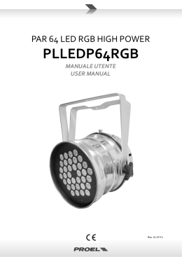
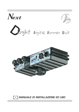
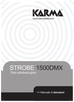
User’s and operator’s manual for art. 9902
Manuale d’uso e dell’operatore per art. 9902
eng
!
WARNING
SAFETY INFORMATION
READ ALL CAUTIONS AND WARNINGS PRIOR TO OPERATE THIS EQUIPMENT.
INSTRUCTION TO PREVENT INJURY OR DAMAGE DUE TO ELECTRIC SHOCK, FIRE, MECHANICAL HAZARDS AND
UV RADIATION HAZARDS.
•PROTECTION AGAINTS FIRE
1)This equipment is designed for use with the following lamps only:
Mastercolour 150W • CDM-T 150W/942 • CDM-SA/T 150W/942
DO NOT USE ANY OTHER TYPE OF LAMP!
2) Maintain minimum distance of 0.3 meter from walls or any other type flammable surfaces.
3) Maintain minimum distance of 1.0 meter to lighted objects .
4) Replace fuses only with the specified type and rating.
5) Do not install the spot close to heat sources. Do not lay the connection cable on the spot when it is warm.
•PROTECTION AGAINST ELECTRIC SHOCK
1) This equipment must be earthed.
2) Class I equipment. The power supply cord includes a protective earthing conductor as part of the cord.
3) For connection to the mains supply proceed as pict.3 page 7.
4) Disconnect power before installing the lamp or servicing (service personnel).
•PROTECTION AGAINST MECHANICAL HAZARDS
1) Use secondary safety chain when fixing this equipment.
2) Hot lamp explosion hazard. Do not open the equipment for 300 seconds after switching off.
3) Equipment surface may reach temperature up to 90°C. Allow about five minutes before handling.
4) Replace the lamp if it is damaged or thermally deformed and however after 6000 life hours.
•PROTECTION AGAINST UV RADIATION HAZARDS
1) Do not start on this equipment without lamp enclosure or if the protection screens, or ultraviolets screens are damaged.
2) The protection screens, the lenses, or the ultraviolet filters must be replaced if they are visibly damaged and their effectiveness
has been reduced, for example, by cracks or deep scratches.
3) Do not look directly at the lamp while lamp is on.
ita
!
IMPORTANTE
INFORMAZIONI DI SICUREZZA
LEGGERE ATTENTAMENTE TUTTI GLI AVVERTIMENTI PRIMA DI COMPIERE QUALUNQUE OPERAZIONE SU QUESTO
APPARECCHIO. ISTRUZIONI PER PREVENIRE LESIONI O DANNI DOVUTI AL FUOCO, ALLE SCOSSE ELETTRICHE,
AI RAGGI ULTRAVIOLETTI ED AI RISCHI MECCANICI.
•PROTEZIONE CONTRO IL FUOCO
1) Questo apparecchio è progettato per funzionare esclusivamente con la lampada:
Mastercolour 150W • CDM-T 150W/942 • CDM-SA/T 150W/942
NON USARE ASSOLUTAMENTE ALTRI TIPI DI LAMPADA!
2) Mantenere la distanza minima di 0.3 metri da pareti ed altre superfici infiammabili.
3) Mantenere la distanza minima di 1.0 metri dagli oggetti illuminati.
4) Sostituire i fusibili solo con altri dello stesso tipo e valore.
5) Non installare il faro vicino fonti di calore. Non appoggiare il cavo di connessione sul faro quando questo è caldo.
•PROTEZIONE CONTRO SCOSSE ELETTRICHE
1) Questo apparecchio necessita di messa a terra.
2) Apparecchio di Classe I. Il conduttore di protezione deve far parte del cavo di alimentazione.
3) Per la connessione all’alimentazione principale procedere come in fig.3, pagina 7.
4) Disconnettere l’alimentazione prima di sostituire la lampada o aprire l’apparecchio (personale di servizio).
•PROTEZIONE CONTRO RISCHI MECCANICI
1) Usare la catena di sicurezza supplementare quando installate il faro.
2) Rischio di esplosione con lampada calda. Non aprire l’apparecchio per 300 secondi dopo lo spegnimento.
3) La temperatura dell’apparecchio può raggiungere 90°C. Attendere circa 5 minuti prima di operare sul faro.
4) Sostituire la lampada se è danneggiata o deformata a causa del calore e comunque dopo 6000 ore di vita.
•PROTEZIONE CONTRO RISCHI DA RADIAZIONE UV
1) Non accendere l’apparecchio senza lo schermo protettivo o se le lenti o i filtri per l’ultravioletto sono danneggiate.
2) Gli schermi di protezione, le lenti, o i filtri ultravioletti, devono essere sostituiti se sono visibilmente danneggiati e se la loro efficacia
è stata ridotta, per esempio, da fessure o incisioni profonde.
3) Non guardare direttamente la lampada quando questa è accesa.
... page 1 ...
eng
INTRODUCTION
Thank you for using the MINICITY, our small and revolutionary architectural light (CYM) spot.
The MINICITY is a CYM flood projector which as been created for static architectural purpose but, however, it is extremely versatile and
can be used also for a traditional application.
The MINICITY comes in unique version:
•Art. 9902 MINICITY for Mastercolour 150W (CDM-T 150W/942 • CDM-SA/T 150W/942)
The input protocol is the DMX 512. To drive the MINICITY we suggest to use either our controllers Mini Control 512, the DMX Control
Spot or the Easy Control, which can drive the MINICITY in the most appropriate way.
To make the most of its possibilites and for a correct functioning of this unit in the years to come, we suggest you to read carefully
this manual before connecting or putting the spot into use. By doing so you will gain experience with its commands and connections
and you will be easily able to use it.
ita
INTRODUZIONE
Vi ringraziamo per l’utilizzo del MINICITY, il nostro piccolo e rivoluzionario faro cambiacolori (CYM) per illuminazione architetturale.
Il MINICITY è un proiettore CYM a diffusione flood che è stato ideato espressamente per l’illuminazione architetturale di tipo fisso,
tuttavia, essendo la configurazione finale estremamente versatile, può essere utilizzato anche per gli usi più tradizionali.
Il MINICITY viene prodotto in unica versione:
•Art. 9902 MINICITY per lampada Mastercolour 150W (CDM-T 150W/942 • CDM-SA/T 150W/942).
Il protocollo di ingresso è il DMX 512. Per il pilotaggio del MINICITY raccomandiamo l’utilizzazione delle nostre centraline Mini Control
512, DMX Control Spot o Easy Control che sono in grado di pilotare il MINICITY in modo ottimale.
Per ottenere il meglio delle prestazioni ed un corretto funzionamento negli anni di questa unità, Vi consigliamo di leggere attentamente questo manuale prima di collegarla e metterla in uso. In questo modo acquisirete familiarità con i suoi comandi e collegamenti
affinché possiate utilizzarla facilmente.
... page 2 ...
eng
YOUR REFERENCE
Always remeber to give the serial number and to specify the model any time you address the seller for information or assistance.
BASIC KIT
The basic kit of the MINICITY spot consists of:
• Projector
• Lamp (upon request)
• Wall fixing plate
• User’s manual
• Studio Due warranty
!
WARNING
Check that the spot has not been damaged during transport. If it has been damaged or it does not work,
address the seller. Whether the spot has been shipped to you directly, please contact the shipping company.
Only the consignee (person or company) can claim for these damages.
ita
VOSTRA REFERENZA
Citate il numero del modello e di serie ogni volta che Vi rivolgete al vostro rivenditore per informazioni o assistenza.
CONFEZIONE BASE
La confezione base del proiettore MINICITY contiene:
• Proiettore
• Lampada (su richiesta)
• Piastra di fissaggio a muro
• Manuale d’uso
• Garanzia Studio Due
!
IMPORTANTE
Controllate che l’apparecchio non abbia subìto alcun danno durante il trasporto.
Se avesse subìto dei danni o se non dovesse funzionare, rivolgetevi al vostro rivenditore. Se l’apparecchio vi è
stato spedito direttamente, rivolgetevi immediatamente alla ditta di trasporto. Solo il destinatario (la persona o
ditta ricevente l’apparecchio) può reclamare per questo tipo di danni.
... page 3 ...
eng
TECHNICAL FEATURES
• LAMP
Mastercolour CDM-T 150W/942 or CDM-SA/T 150W/942)
Averange lamp life: 6000 hours
Colour temperature: 4200 K
Luminous flux: 12700 lumen
Colour rendering index: 96 Ra
• OPTIC COLOUR SYSTEM
New concept optical system (patent pending)
Full CYM color mixing, unlimited variety of colours and shades
High resolution stepper motors
Colour crossfades can be programmed at four different speeds or in real time
• CONTROL INPUT
Interface standard: RS-485; opto-coupled input
Protocol: USITT DMX 512
Stand-alone control: auto mode function master/slave (synchro mode)
• POWER SUPPLY
Rated voltage: 230 Vac • on request: 208 Vac 60 Hz; 200 Vac 50 Hz
Rated frequency: 50 or 60 Hz
Rated current: 1,1A
Rated power: 250 Va
• FUSES
Lamp fuse: 3,15A/250V T (time-delay)
Electronics fuse: 1A/250V T (time delay)
ita
CARATTERISTICHE TECNICHE
• LAMPADA
Mastercolour CDM-T 150W/942 or CDM-SA/T 150W/942)
Durata lampada: 6000 ore
Temperatura colore: 4200 K
Flusso luminoso: 12700 lumen
Indice di resa colore: 96 Ra
• SISTEMA OTTICO/COLORI
Sistema ottico di nuova concezione (patent pending)
Miscelazione di colori (CYM) completa, infinite varietà di colori e sfumature
Motori passo-passo ad alta risoluzione
Dissolvenza colori programmabile in quattro differenti velocità o in tempo reale
• CONTROLLO INGRESSO
Interfaccia standard: RS-485; ingresso foto-accoppiato
Protocollo: USITT DMX 512
Controllo in automatico: funzione auto mode master/slave (modo sincrono)
• POTENZA INGRESSO
Tensione nominale: 230 Vac • a richiesta: 208 Vac 60 Hz; 200 Vac 50 Hz
Frequenza nominale: 50 o 60 Hz
Corrente nominale: 1,1A
Potenza nominale: 250 Va
• FUSIBILI
Fusibile lampada: 3,15A/250V T (ritardati)
Fusibile elettronica: 1A/250V T (ritardati)
... page 4 ...
eng
BEFORE USING
!
WARNING
The equipment must be earthed.
If this rule is not followed, the warranty will be void.
Read all cautions and warnings to page 1 prior to install this equipment. Particularly, read the following:
Before connecting the equipment to the power system:
1) Make sure that the mains voltage and frequency correspond to rated values shown on the label (pict. 1).
2) Connect the mains power cable to the electronic boards inside and if necessary (synchro-mode) the DMX cable (see page 7).
The MINICITY is made for a mains voltage 230V 50 Hz; 1,1A
For a power supply of 100V-120V it is necessary to use one auto transformer with the following features:
• Output voltage 230V.
• Output current 2A.
Before any operation on the fixture
a) Disconnect power before lamp’s replacement (page 6) or servicing (service personnel).
b) Do not open the lamp cover for 300 seconds after switching off.
c) Wear gloves and goggles to re-lamping (page 6) or to work inside the unit (service personnel).
Do not install the spot close to heat sources. Do not lay the connection cable on the spot when it is warm.
The unit must be positioned at least 30 cm. from walls or other flammable surfaces and minimum 1.0 meter to lighted objects.
External surfaces temperature:
• After 5 minutes work; Tc=75°C. • Once the thermic balance has been obtained; Tc=90°C.
DMX IN • DMX OUT
pict./fig.1
POWER INPUT/
INGRESSO ALIMENTAZIONE
ita
PRIMA DELL’USO
!
IMPORTANTE
L’apparecchio necessita di messa a terra; l’inosservanza di questa norma
comporta automaticamente il decadere della garanzia.
Leggere attentamente le istruzioni a pagina 1 prima di installare l’apparecchio. In particolare quanto segue:
Prima di collegare l’apparecchio all’alimentazione:
1) Assicurarsi che la tensione e la frequenza di esercizio corrispondano ai valori indicati sull’etichetta (fig. 1).
2) Collegare i cavi dell’alimentazione al circuito elettronico interno e se necessario (modo sincrono) i cavi DMX (vedere pag. 7).
Il MINICITY è fornito per una tensione di lavoro di 230V 50 Hz; 1,1A.
Per un’alimentazione di 100-120V è assolutamente necessario un autotrasformatore con le seguenti caratteristiche:
• Tensione d’uscita 230V.
• Corrente d’uscita 2A.
Prima di qualsiasi operazione sull’apparecchio:
a) Disconnettere l’alimentazione prima di sostituire la lampada (pag. 6) o effettuare la manutenzione (personale di servizio) .
b) Non aprire il coperchio della lampada prima di 300 secondi dopo lo spegnimento.
c) Indossare guanti ed occhiali di protezione per sostituire la lampada (pag. 6) o per lavorare all’interno del faro (personale di servizio).
Evitare di installare l’unità in prossimità di fonti di calore. Non appoggiare il cavo di collegamento sull’apparecchio caldo.
L’unità deve inoltre distare almeno 30 cm. da pareti o altre superfici infiammabili ed almeno 1 metro dagli oggetti illuminati.
Temperatura sulle superfici esterne dell’apparecchio:
• Dopo 5 minuti di funzionamento; Tc = 75°. • Quando e’ stato raggiunto l’equilibrio termico; Tc = 90°.
... page 5 ...
eng
d) Replace the lamp when the lamp life is exhausted (6000 hours) to avoid bad peformances of the fixture or that the optic system is
damaged by the lamp explosion.
e) The protection screens, the lenses, or the ultraviolet filters must be replaced if they are visibly damaged and their effectiveness has
been reduced, for example, by cracks or deep scratches.
f) The lamp must be replaced if it has been damaged or thermally deformed.
g) In case of installation of the spot to a truss, check carefully that the fixture is fixed with a chain to both truss and unit.
INSTALLATION OF THE LAMP
(pict. 2)
!
WARNING
In case of replacement of the lamp or maintenance, do not open
the fixture unless 5 minutes have passed from the switching off.
1) Disconnect power before installing the lamp. Wear gloves and goggles.
2) Unscrews the four screws on the glass cover and fully open the six dichroic blades (C).
3) Unscrews the screws A and B and remove the reflector parabole (D).
4) Insert the lamp (E) into the lampholder socket. Do not touch the quarz bulb with fingers. If this happenes, clean the bulb
before use with dry cloth and alcohol. Polish with a dry cloth.
5) Screws the glass cover.
PARABOLE (D)
DICHROIC BLADE (C)
LAMP (E)
SCREW (B)
SCREW (A)
pict./fig.2
ita
d) Sostituire la lampada quando raggiunge la durata massima di vita (6000 ore) per evitare che le prestazioni dell’apparecchio
scadano
o che esplodendo danneggi il sistema ottico.
e) Gli schermi di protezione, le lenti o i filtri per l’ultravioletto devono essere sostituiti se sono visibilmente danneggiati al punto che
la
loro efficacia ne sia diminuita, per esempio da fessure o incisioni profonde.
f) La lampada deve essere sostituita se essa e’ stata danneggiata o deformata dal calore.
g) In caso di installazione a struttura, controllare che il faro sia ben fissato con una catena alla struttura ed anche all’unità stessa.
INSERIMENTO LAMPADA
(fig. 2)
!
IMPORTANTE
In caso di cambio lampada o manutenzione, non aprire mai l’apparecchio
se non sono trascorsi almeno 5 minuti dopo lo spegnimento.
1) Disconnettere l’apparecchio prima di sostituire la lampada. Indossare guanti ed occhiali di protezione.
2) Dopo aver aperto il coperchio del faro agendo sulle quattro viti, aprire completamente le palette dei dicroici (C).
3) Svitare le viti A e B ed estrarre la parabola (D).
4) Inserire la lampada (E) nell’apposito zoccolo portalampada. Non toccare il bulbo della lampada con le dita.
Se questo avviene pulirlo con un panno asciutto ed alcool.
5) Riavvitare il coperchio del faro.
... page 6 ...
eng
CONNECTION TO THE MAINS POWER AND TO THE DMX SIGNAL
To connect the MINICITY to the mains power, remove the cover located behind the fixture, and connect the cable to the electronic
board as shown in pict. 3.
The connection to the DMX signal to the MINICITY must be made by using standard DMX cables as shown in pict. 3/a
!
WARNING
HIGH VOLTAGE!
Always disconnect the mains supply before opening the connections area.
To ensure the IP55 rate choose the correct size of the cables (from 3 to 6.5 mm.)
In order to avoid any problem in the signal transmission, it is warmly suggested to use a cable for high speed data transmission.
The usage of a normal microphonic or audio cable is suggested only for lines max 100 mts long.
If the lines have a total length over 150-200 mts it is suggested to use our DMX Repeater Amplifier.
MAINS VOLTAGE CABLE 230 Vac/
CAVO DI ALIMENTAZIONE 230 Vac
pict./fig.3
pict./fig.3/a
DMX CABLE/
CAVO DMX
DMX CABLE/
CAVO DMX
ita
CONNESSIONE ALLA RETE ED AL SEGNALE DMX
Per collegare l’apparecchio alla rete, rimuovere il coperchio in plastica posto sul retro del faro, e collegare il cavo alla scheda elettronica
come descritto in figura 3.
La connessione del segnale DMX con il MINICITY deve essere effettuata tramite cavi DMX come descritto in fig. 3/a.
!
IMPORTANTE
ALTA TENSIONE!
Scollegare sempre l’alimentazione prima di aprire il vano dei collegamenti.
Per garantire il grado di protezione IP55 usare solo cavi di sezione da 3 a 6.5 mm.
Al fine di evitare problemi nella trasmissione del segnale è raccomandato l’utilizzo di un cavo adatto a trasmissioni dati ad alta velocità.
L’uso di un normale cavo microfonico o audio è consigliabile soltanto per linee di lunghezza non superiore ai 100 metri.
In caso di linee con lunghezza totale oltre i 150-200 metri è consigliabile utilizzare il nostro DMX Repeater Amplifier.
... page 7 ...
eng
DMX TERMINAL LINE
The wrong connection of the terminal line or its non-connection are probably the most frequent reasons for the defective functioning
of the DMX line. The terminator is a terminal resistor fitted at the end of the cable furthest from the transmitter (see page 10).
The terminal resistor should have the same value as the impedance of the connection cable.
We suggest to use a terminal with a 100 ohm resistor.
It is recommanded that all DMX 512 systems have the terminal resistor fitted in the DMX output of the last fixture.
MINICITY SETUP
!
WARNING
HIGH VOLTAGE!
Always disconnect the mains supply before opening the connections area.
• DMX 512 CONTROL
1) Connect the DMX data cable coming from the controller to the DMX-IN connector on the electronic board (see pict. 3/a page 7).
2) Connect the DMX data cable to the DMX-OUT connector on the electronic board to control the next MINICITY (see pict. 3/a page 7).
3) Select the DMX starting address by operating on the rotary switches (UNITS, TENS, HUNDREDS).
DMX 512 CHANNELS ASSIGNEMENT IN THE MINICITY
The rotating switches to assign the channels in the MINICITY in DMX 512 are located on the printed circuit of the electronics which is
inside the connections area.
There are three rotating switches, and each one is numbered from 0 to 9: one for the UNITS, one for the TENS, one for the HUNDREDS.
In the picture below it is shown the position of the three switches when using four MINICITY in DMX 512.
ita
TERMINALE LINEA DMX
L’incorretto o il mancato collegamento del terminale di linea è probabilmente la più comune causa del difettoso funzionamento della
linea DMX. Il terminale di linea DMX consiste in una resistenza posta alla fine della linea (vedere pagina 10).
La resistenza terminale dovrebbe avere idealmente lo stesso valore dell’impedenza del cavo di collegamento.
Noi forniamo un terminale con una resistenza da 100 ohm.
E’ raccomandato per tutti i sistemi DMX 512 inserire il teminale di linea nel connettore uscita DMX dell’ultimo apparecchio collegato.
SETTAGGIO DEL MINICITY
!
IMPORTANTE
ALTA TENSIONE!
Scollegare sempre l’alimentazione prima di aprire il vano dei collegamenti
• CONTROLLO CON CENTRALINA DMX 512
1) Collegare il cavo DMX proveniente dalla centralina all’ingresso (DMX-IN) sulla scheda elettronica (vedere pag. 7 fig. 3/a).
2) Collegare il cavo DMX all’uscita (DMX-OUT) sulla scheda elettronica, per pilotare l’apparecchio successivo (vedere pag. 7 fig. 3/a).
3) Selezionare il canale DMX di partenza dell’apparecchio agendo sui commutatori rotativi (UNITA’, DECINE, CENTINAIA).
ASSEGNAZIONE CANALI DEL MINICITY IN DMX 512
I commutatori rotativi per assegnare i canali del MINICITY in DMX 512 sono situati sul circuito stampato dell’elettronica posto all’interno
del vano collegamenti.
I commutatori rotativi sono tre, numerati ognuno da 0 a 9, e sono rispettivamente uno per le UNITA’, uno per la DECINE, uno per le
CENTINAIA. Nella figura in basso è riportata la posizione dei tre commutatori per l’utilizzo di quattro MINICITY in DMX 512.
Spot n° 1
Faro n° 1
Spot n° 2
Faro n° 2
Spot n° 3
Faro n° 3
Spot n° 4
Faro n° 4
Channels 1-6
Canali 1-6
Channels 7-12
Canali 7-12
Channels 13-18
Canali 13-18
Channels 19-24
Canali 19-24
... page 8 ...
EXAMPLE OF CONNECTION DMX CONTROLLER-SPOT / ESEMPIO DI COLLEGAMENTO CENTRALINA - FARI
DMX CONTROLLER OR LIGHT CONSOLE/
CENTRALINA O BANCO DMX
SPOT
SPOT
SPOT
LAST SPOT/
ULTIMO SPOT
EXAMPLE 1/ESEMPIO 1
Connection controller-spot with
1 DMX 512 OUTPUT
Collegamento centralina-spot ad
una sola LINEA DI USCITA DMX
512
TERMINATION
RESISTOR/
TERMINALE
DI LINEA
SPOT
SPOT
SPOT
DMX CONTROLLER OR LIGHT CONSOLE/
CENTRALINA O BANCO DMX
LAST SPOT/
ULTIMO SPOT
DMX1 output/linea uscita DMX1
DMX2 output/linea uscita DMX2
TERMINATION
RESISTOR/
TERMINALE
DI LINEA
SPOT
SPOT
SPOT
EXAMPLE 2/ESEMPIO 2
Connection controller-spot with
2 or more DMX 512 OUTPUT
Collegamento centralina-spot a
due o più LINEE DI USCITA DMX 512
TERMINATION
RESISTOR/
TERMINALE
DI LINEA
DMX CONTROLLER OR LIGHT CONSOLE/
CENTRALINA O BANCO DMX
EXAMPLE 3/ESEMPIO 3
Connection controller-spot to
1 DMX 512 OUTPUT over 150mts long
Collegamento centralina-spot ad una sola
LINEA DI USCITA DMX 512 lunga oltre
150mt.
SPOT
LAST SPOT
ULTIMO SPOT
LINE > 150mts (with microphonic or audio cable)
LINEA > 150mt (con cavo microfonico o audio)
DMX CONTROLLER OR LIGHT CONSOLE/
CENTRALINA O BANCO DMX
SPOT
EXAMPLE 4/ESEMPIO 4
Connection controller-spot to
1 DMX 512 OUTPUT over 150mts long
Collegamento centralina-spot ad una sola
LINEA DI USCITA DMX 512 lunga oltre
150mt.
TERMINATION RESISTOR/
TERMINALE DI LINEA
LAST SPOT/
ULTIMO SPOT
LINE > 150mts (with microphonic or audio cable)
LINEA > 150mt (con cavo microfonico o audio)
... page 9 ...
TERMINATION RESISTOR/
TERMINALE DI LINEA
eng
MINICITY SETUP
!
WARNING
HIGH VOLTAGE!
Always disconnect the mains supply before opening the connections area.
• AUTO - MODE CONTROL
1) Set n° 6 on the HUNDREDS rotary switch (MASTER).
2) Choose the games by operating on the UNITS and TENS rotary switches.
Available games: from n° 1 to n° 15 (see appendix “B” to page 11). Game n° 11 is the one which enables all the colors.
• SYNCHRO - MODE CONTROL
(pict. below)
1) Interconnect all the MINICITY (max 32) by using the DMX standard cables.
2) Set the first MINICITY as MASTER by setting n° 6 on the HUNDREDS rotary switch.
3) Choose the games by operating on the UNITS and TENS rotary switches (on MASTER fixture). Games: from n° 1 to n° 15
4) Set all the rest of the MINICITY as SLAVE by setting n° 7 on the HUNDREDS rotary switch.
ita
SETTAGGIO DEL MINICITY
!
IMPORTANTE
ALTA TENSIONE!
Scollegare sempre l’alimentazione prima di aprire il vano dei collegamenti
• CONTROLLO IN MODO AUTOMATICO
1) Selezionare il n° 6 sul commutatore rotativo delle CENTINAIA (MASTER).
2) Scegliere i giochi agendo sui commutatori rotativi delle DECINE e delle UNITA’.
Sono disponibili 15 giochi, dal n° 1 al n° 15 (vedere appendice “B” a pag. 11). Il gioco n° 11 e quello che abilita tutti i colori.
• CONTROLLO IN MODO SINCRONO
(fig.in basso)
1) Interconnettere tutti i MINICITY (massimo 32) tramite le prese DMX-OUT e DMX-IN, usando un cavo DMX standard.
2) Settare il primo MINICITY come MASTER selezionando il n° 6 sul commutatore rotativo delle CENTINAIA.
3) Scegliere sull’apprecchio MASTER il gioco agendo sui commutatori rotativi delle DECINE e delle UNITA’.
I giochi sono dal n° 1 al n° 15.
4) Settare tutti gli altri apparecchi come SLAVE selezionando su ognuno di essi il n° 7 sul commutatore rotativo delle CENTINAIA.
EXAMPLE OF CONNECTION AND SETTING OF 4 MINIITY IN SYNCHRO-MODE
ESEMPIO DI COLLEGAMENTO E SETTAGGIO DI 4 MINICITY IN MODO AUTOMATICO SINCRONIZZATO
MINICITY 1 as MASTER
example GAME 12
MINICITY 1 come
MASTER
esempio GIOCO 12
MINICITY 2 as SLAVE
MINICITY 3 as SLAVE
MINICITY 4 as SLAVE
MINICITY 2 come SLAVE
MINICITY 3 come SLAVE
MINICITY 4 come SLAVE
... page 10 ...
eng
APPENDIX “B”
Here below you can find the complete list of available games.
ita
APPENDICE “B”
Diamo di seguito la lista completa dei giochi disponibili.
... page 11 ...
SPARE PARTS, TECHNICAL DRAWINGS and SCHEMATIC DIAGRAMS
... page 12 ...
•TECHNICAL
DRAWING•
... page 13 ...
•MAIN BOARD•
... page 14 ...
•ELECTRONIC DIAGRAM•
... page 15...
NOTE
... page 16 ...
Head Office: STUDIO DUE Light Division s.r.l.
Str. Poggino, 100 - 01100 Viterbo (Italy)
tel. +39/761/353902 • +39/761/352520
fax +39/761/352653
Asia branch: STUDIO DUE Far East LTD
Unit D 29/F West Gate Tower
7 Wing Hong Street Kln. Hong Kong
tel. +852/29542141
fax +852/23302515
Web site • www.studiodue.com
Studio Due E Mail • [email protected]
For informations • [email protected]
Rev • 1-12/99
The features on this brochure are not binding: they can be changed
without notice.
Le caratteristiche riportate su questo catalogo non sono impegnative e
possono essere soggette a variazioni senza preavviso.
Scaricare