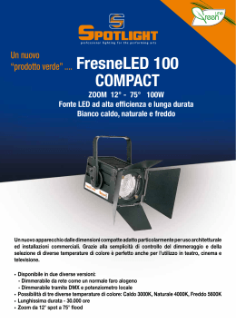
Manuale utente - User manual
FresneLED 100 DMX
FresneLED e PCLED 100 DMX Compact
cod. FN LED 100 CW DMX • FN LED 100 WW DMX • FN LED 100 NW DMX
FN LED C100 CW DMX • FN LED C100 WW DMX • FN LED C100 NW DMX
PC LED C100 CW DMX • PC LED C100 WW DMX • PC LED C100 NW DMX
FresneLED e PCLED 100 DMX
ATTENZIONE: Prima di usare questi apparecchi,
leggere attentamente le istruzioni che seguono.
Spotlight srl non potrà essere ritenuta responsabile di
danni derivanti dalla non osservanza di dette istruzioni.
SAFETY WARNING:
ITALIANO: Pag. 3
ENGLISH: Pag. 6
Before using this product,
read the present instructions carefully.
Spotlight srl will not be responsible for damage
resulting from instructions not being followed.
1
4
9
X10
3
X1
8
DMX ADDRESS
X100
2
DM
X TH
RU
DM
X IN
5
7
6
Fig. 1
901
78
901
901
901
78
78
901
78
78
901
DMX ADDRESS
X1
23
456
78
2
X10
23
456
Fig. 2
X100
23
456
23
456
X1
23
456
X10
456
X100
23
DMX ADDRESS
Selettori di impostazione modalità - Mode setup selectors
FresneLED e PCLED 100 DMX
Connessioni elettriche e DMX - Electrical and DMX connections
0
X10
X1
DMX ADDRESS
X10
DM
X TH
RU
0
X10
X1
X IN
DMX ADDRESS
X10
DM
DM
X TH
RU
0
X10
X1
DMX ADDRESS
X10
DM
DM
X TH
RU
X IN
0
X10
DMX OUT
X1
DM
DMX ADDRESS
X10
DMX IN
DM
X TH
RU
X IN
DMX IN
DMX OUT
DM
X IN
DMX IN
DMX OUT
DMX IN
CONSOLE
100-240V
Fig. 3
Dimensioni (mm) e pesi - Dimensions (mm) and weights
FresneLED 100 DMX
317
Fig. 4
305
290
215
330
280
Fresneled e PCLED 100 DMX compact
Kg. 5,7
Kg. 3,5
3
FresneLED e PCLED 100 DMX
DESCRIZIONE DEL PROIETTORE
CONNESSIONI ELETTRICHE
Riferendosi ai disegni di pag. 2:
Il vostro faro è stato progettato per una tensione di
alimentazione da 100 a 240V, 50/60 Hz.
① Staffa di sospensione
② Maniglia per regolazione inclinazione del faro
③ Guide porta accessori con tettuccio di ritenzione
④ Molla per bloccaggio tettuccio accessori
⑤ Pomolo per regolazione dello zoom
⑥ Connettore DMX IN
⑦ Connettore DMX THRU
⑧ Selettori di impostazione modalità (contraves)
⑨ Manopola di regolazione intensità luminosa
(in modalità Potenziometro locale)
Prima e durante l’installazione osservare le seguenti
norme:
• Verificare sempre l’efficienza del collegamento a terra
della linea in uso.
• Verificare che la tensione di alimentazione corrisponda a
quella dell’apparecchio
• L’apparecchio è previsto per uso all’interno: pertanto
deve essere protetto dall’umidità e dalla pioggia se
usato in condizioni diverse (IP 20).
• L’apparecchio NON può essere collegato a un dimmer.
INDICAZIONI GENERALI
Il proiettore in Vs possesso risponde alle Direttive
Europee 2006/95/CE, 2004/108/CE e 2011/65/UE.
La targhetta che è sistemata sul fianco del proiettore,
contiene le seguenti informazioni:
PUNTAMENTO
• Modello
• Tensione di alimentazione in V
• Potenza in W
• Indice di protezione IP
• Massima temperatura ambiente ammissibile in °C
• Distanza minima da ogni superficie infiammabile
Tramite la maniglia laterale ② si può allentare il
bloccaggio del faro in una certa posizione e modificare
la sua inclinazione. Lo stesso si può fare riguardo alla
rotazione sull’asse verticale, facendolo ruotare sul perno
di aggancio.
Il proiettore deve essere collocato rispettando la
distanza minima dall’oggetto che si deve illuminare,
indicata sull’etichetta del faro.
Per la regolazione dello zoom ruotare in senso orario o
antiorario il pomello ⑤, rispettivamente per stringere o
allargare il fascio luminoso.
INSTALLAZIONE
• Il proiettore è progettato esclusivamente per impiego
professionale.
• Non puntare il faro direttamente negli occhi
• Si prega di prestare la dovuta attenzione alle note
riportate sull’etichetta dell’apparecchio.
• Ricordarsi di collegare la fune di sicurezza se previsto
dalle norme di sicurezza locali.
• ll proiettore può essere usato sia sospeso sia montato
su cavalletto.
MANUTENZIONE
Non aprire l’apparecchio. La manutenzione deve essere
eseguita esclusivamente dal costruttore o dal suo
servizio di assistenza.
Sottoporre il faro a revisione almeno una volta all’anno
per controllare l’integrità delle parti elettriche e
meccaniche e l’aggiornamento del software.
RICICLAGGIO
ATTENZIONE: Gli apparecchi devono essere
collegati a terra
Il prodotto deve essere riciclato o smaltito
secondo la direttiva 2002/96/CE
4
•
•
•
•
•
Per il controllo in questa modalità è necessario il
collegamento tramite cavo DMX da un dispositivo
di controllo (es. console) al connettore del faro
DMX IN.
E’ possibile assegnare un qualsiasi indirizzo DMX
compreso fra 001 e 512, seguendo le indicazioni
descitte nel precedente paragrafo.
Più fari possono essere connessi in cascata,
collegando l’uscita DMX THRU di un faro
all’ingresso DMX IN del faro successivo (Fig. 3).
L’assegnazione dello stesso indirizzo DMX a più
fari permetterà il controllo contemporaneo degli
apparecchi. Assegnando un diverso indirizzo si
potranno controllare singolarmente.
POTENZIOMETRO LOCALE
DMX
RDM
MANUALE
ON / OFF
L’impostazione della modalità viene effettuata
attraverso l’assegnazione di un valore compreso fra
000 e 999 secondo lo schema seguente:
- 000
- 001 fino a 512 - 600
- 900 fino 999
- 999
POTENZIOMETRO LOCALE
DMX (Indirizzo)
RDM
MANUALE
ON / OFF
3)Modalità RDM (600)
Il protocollo di controllo RDM utilizza la linea DMX
per inviare/ricevere informazioni, a/da il faro, che
riguardano il settaggio dell’apparecchio, l’indirizzo
DMX, l’impostazione remota delle modalità di
funzionamento, la verifica della temperatura dei
led, la versione di software installata, ecc.
Il numero delle funzioni gestite dal sistema RDM
dipende dalla versione di programma RDM
residente nel PC preposto allo scopo o dalla
consolle di comando se abilitata a questa funzione.
I valori possono essere assegnati utilizzando i selettori
(contraves) posti nella parte posteriore del faro ⑧,
indicati con X100, X10, X1, che dovranno essere
ruotati in modo da far corrispondere la freccia di ogni
selettore con il valore desiderato in centinaia decine
e unità.
Es.: impostazione di modalità DMX con indirizzo 235
901
901
901
901
78
901
78
78
78
901
78
23
456
X1
23
DMX ADDRESS
X10
23
456
23
X100
456
23
DMX ADDRESS
23
456
78
X1
2)Modalità DMX (001-512)
Il faro è predisposto per poter essere utilizzato in
diverse modalità di funzionamento:
456
10
IMPOSTAZIONE MODALITA' DI FUNZIONAMENTO
(vedi Fig. 2)
456
00
FresneLED e PCLED 100 DMX
4)Modalità MANUALE (900-999)
La modalità manuale consente di impostare
l’intensità luminosa del proprio faro in modo
percentuale da 1% a 100%, ponendo i selettori ad
un valore compreso fra 900 (1%) e 999 (100%).
5)Modalità ON / OFF (999)
In questa modalità il faro funziona alla massima
intensità luminosa una volta collegato alla rete e si
spegne quando viene scollegato. In questa modalità
non è possibile la regolazione dell’intensità
luminosa.
1)Modalità POTENZIOMETRO LOCALE (000)
Questa è la configurazione di fabbrica del prodotto.
In questa modalità è possibile regolare l’intensità
luminosa dell’apparecchio da 0% a 100%
utilizzando l’apposita manopola ⑨.
5
FresneLED e PCLED 100 DMX
DESCRIPTION OF THE LUMINAIRE
ELECTRICAL CONNECTIONS
Referring to pictures on pages 2:
The luminaire has been designed to operate with a 100V
to 240V supply, 50-60Hz.
① Suspension yoke
② Handle for tilt regulation
③ Accessory guides with retaining clip
④ Accessory locking spring
⑤ Zoom adjustment knob
⑥ DMX IN connector
⑦ DMX THRU connector
⑧ Mode setup selectors
⑨ Light intensity adjustment knob
(in Local Potentiometer mode)
Before and during the installation, make sure you
follow the guidelines below:
• Always check the earth continuity connection for the
line being used.
• Ensure the required voltage of the unit is the same as
the supplied one.
• The unit is designed for indoor use: if it is to be used
outdoor, ensure it is protected from dampness and
rain. (IP 20)
• This unit cannot be connected to a dimmer.
INTRODUCTION
FOCUSING
The luminaire you have bought complies to 2006/95/EC,
2004/108/EC and 2011/65/EU European Directives.
The label on the side of the luminaire lists the following
information:
The luminaire should be at the minimum distance from
the object it is illuminating, as indicated on the label.
Using the side handle ② allows to loosen the luminaire
when it is locked in a certain position and thus change
its inclination. You can rotate the luminaire on the
vertical axis by rotating it on its hook clamp.
• Model
• Mains supply voltage (V)
• Lamp wattage (W)
• Protection index (IP)
• maximum allowed ambient temperature in °C
• minimum flammable surface distance
For the zoom adjustment rotate knob ⑤ clockwise or
counterclockwise to respectively narrow or widen the
light beam.
MAINTENANCE
Do not open the fixture. Maintenance should be
performed only by the manufacturer or by its service
agent.
The luminaire must be serviced at least once a year, to
check the integrity of its electrical and mechanical parts
and to keep software updated.
INSTALLATION
•The luminaire has been designed for professional use
only
•Do not direct the light beam straight into somebody’s
eyes
•Read carefully the information label on the side of the
luminaire
•Remember to connect the safety cable, if required by
local health and safety regulations
•The luminaire can be either suspended or mounted on
a stand.
RECYCLING
The product must be recycled or disposed of,
according to Directive 2002/96/CE.
WARNING:
The luminaires must always be earthed
6
•
•
•
•
•
For the control in this mode the connection through
a DMX cable from a control device (eg. consolle) to
the DMX IN luminaire connector is necessary.
It is possible to assign any DMX address between 001
and 512, following the indications described in the
previous paragraph.
More luminaires can be connected in cascade by
connecting the DMX THRU of another luminaire to
the DMX IN of the following fixture (see Fig. 3).
The assignment of the same DMX address to more
luminaires will allow a simultaneous control of the
fixtures. Assigning a different address will allow to
control them individually.
LOCAL POTENTIOMETER
DMX
RDM
MANUAL
ON / OFF
The mode set up is done by assigning a value between
000 and 999 according to the following scheme:
- 000
- 001 up to 512 - 600
- 900 up to 999
- 999
LOCAL POTENTIOMETER
DMX (Address)
RDM
MANUAL
ON / OFF
3)RDM Mode (600)
The RDM control protocol uses the DMX line to send/
receive information to/from the luminaire regarding
the fixture set up the DMX address, the remote set
up of the functioning modes, the LED temperature
check, the installed software version, etc.
The number of functions handled by the RDM system
depends on the RDM programme version in the PC
designated for the purpose or on the lighting desk, if
enabled for this function.
Values can be assigned using the selectors (contraves)
on the rear of the luminaire ⑧, marked with X100, X10,
X1, which will have to be rotated so the arrows of each
sector correspond to the desired value in hundreds,
tens an units.
Eg.: DMX set up with address 235
901
901
901
901
78
901
78
78
78
901
78
23
456
X1
23
DMX ADDRESS
X10
23
456
23
X100
456
23
DMX ADDRESS
23
456
78
X1
2)DMX Mode (001-512)
The luminaire is intended to be used in various
functioning modes:
456
10
FUNCTIONING SET UP (see Fig. 2)
456
00
FresneLED e PCLED 100 DMX
4)MANUAL Mode (900-999)
The manual mode allows to set up the light output
of every luminaire in percentage from 1% to 100%,
with selectors value between 900 (1%) and 999
(100%).
5)ON / OFF Mode (999)
In this mode the luminaire works at the maximum
light output once connected to the mains and it
switches off when disconnected. In this mode no
light output adjustment is allowed.
1)LOCAL POTENTIOMETER Mode (000)
This is the manufacturer configuration. This mode
allows to adjust the light ouput of the luminaire
from 0% to 100% by using the appropriate knob ⑨
7
FresneLED e PCLED 100 DMX
certified quality management system ISO 9001 : 2008
Spotlight s.r.l.
Via Sardegna 3
20098 S. Giuliano Milanese
Milano - Italy
Tel. +39.02.98830.1
Fax +39.02.98830.22
E-mai: [email protected]
www.spotlight.it
Scaricare