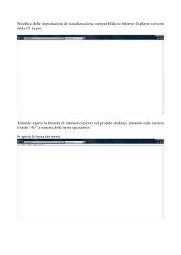
EXTRA
IT - Istruzioni per l’uso e per il tecnico autorizato
GB - Operating instructions and guidelines for authorised technicians
IT
GB
AVVERTENZE GENERALI
GENERAL INSTRUCTIONS
1. Il presente libretto costituisce parte
integrante ed essenziale del prodotto.
Va conservato con cura e dovrà sempre
accompagnare l’apparecchio anche in caso
di sua cessione ad altro proprietario o utente
e/o di trasferimento su altro impianto.
2. Leggere attentamente le istruzioni e le
avvertenze contenute nel presente libretto,
in quanto forniscono importanti indicazioni
riguardanti la sicurezza d’installazione,
d’uso e di manutenzione.
3. L’installazione è a cura dell’acquirente
e deve essere realizzata da personale
qualificato seguendo le istruzioni riportate
su questo libretto.
4. È vietata l’utilizzazione di questo apparecchio
per scopi diversi da quanto specificato.
La ditta costruttrice non è considerata
responsabile per eventuali danni derivanti
da usi impropri, erronei ed irragionevoli
o da un mancato rispetto delle istruzioni
riportate in questo libretto.
5. L’installazione, la manutenzione e qualsiasi
altro intervento, devono essere effettuate
da personale qualificato nel rispetto di tutte
le norme vigenti e delle indicazioni fornite
dalla ditta costruttrice.
6. Un’errata installazione può causare danni a
persone, animali o cose per i quali la ditta
costruttrice non è responsabile
7. Gli elementi di imballaggio (graffe, sacchetti
in plastica, polistirolo espanso, ecc.) non
devono essere lasciati alla portata dei
bambini in quanto fonti di pericolo.
8. È vietato operare sull’apparecchio da parte
di bambini, persone inesperte o in possesso
di facoltà fisiche, sensoriali o psichiche
limitate o prive di esperienza e/o conoscenze
a meno che costoro non vengano sorvegliati
da una persona responsabile della loro
sicurezza o ricevano da quest’ultima
istruzioni sull’uso dell’apparecchio.
9. I bambini vanno sorvegliati per evitare che
giochino con l’apparecchio
10. È vietato toccare l’apparecchio se si è a piedi
nudi o con parti del corpo bagnate.
11. Eventuali riparazioni devono essere
effettuate solamente da personale
qualificato utilizzando esclusivamente
ricambi originali.
Il mancato rispetto di quanto sopra può
compromettere la sicurezza e fa decadere
ogni responsabilità del costruttore.
12. Nessun oggetto infiammabile deve trovarsi
nelle vicinanze dell’apparecchio.
13. Un uso conforme alla destinazione
comprende anche il rispetto delle istruzioni
per l’uso e per l’installazione e di tutta
la documentazione integrativa nonché
il rispetto delle condizioni di ispezione e
manutenzione.
14. Qualsiasi altro uso non conforme è vietato.
1. This manual constitutes an integral and
essential part of the product. It should be
preserved with care and must accompany
the appliance, even if the product is
transferred to another owner or user and/or
moved to another installation site.
2. Carefully read the instructions and
warnings contained in this manual; they
provide important information for the safe
installation, use and maintenance of your
new appliance.
3. Installation is the responsibility of the
buyer and should be performed by
qualified personnel in accordance with the
instructions contained herein.
4. Using this appliance for purposes other
than those specified is strictly forbidden.
The manufacturer shall not be held
responsible for any damage due to improper,
incorrect and unreasonable use or due to
failure to comply with the instructions set
out in this manual.
5. Installation, maintenance and all other
interventions must be carried out by
qualified personnel in full conformity with
all applicable legal regulations and the
instructions provided by the manufacturer.
6. Incorrect installation may lead to personal
injury or property damage and may harm
animals; the manufacturer shall not be held
responsible for such damage.
7. Keep all packaging material (clips, plastic
bags, expanded polystyrene, etc.) out of
reach of children, as it may be potentially
dangerous.
8. Children, inexperienced persons, persons
with limited physical, sensory or mental
abilities or lacking the necessary know-how
and expertise may not operate the appliance
unless adequately supervised or instructed
on its use by a person responsible for their
safety.
9. Children must be supervised at all times,
to ensure that they do not play with the
appliance.
10. Do not touch the appliance while barefoot or
with wet hands or feet.
11. All repairs should be performed exclusively
by qualified personnel, using authentic
spare parts only.
Failure to comply with the above instructions
could compromise safety and will exempt
the manufacturer from all liability.
12. No flammable items should be left in the
vicinity of the appliance.
13. Proper use of the appliance also includes
complying with the use and installation
instructions and with the supplementary
documentation, in addition to the inspection
and maintenance terms.
14. Any other improper use is forbidden.
APPARECCHIO
CONFORME
ALLE
NORME:
EN 60335-1 : EN 61000-4-2,3,4,5,6,11,13
EN 60335-2-21 - EN 12897
EN 55014 -1,2 - EN 61000-3-2,3
EN 62233
2
APPLIANCE COMPLIES WITH NORMS:
EN 60335-1 : EN 61000-4-2,3,4,5,6,11,13
EN 60335-2-21 - EN 12897
EN 55014 -1,2 - EN 61000-3-2,3
EN 62233
IT
GB
NORME DI SICUREZZA GENERALI
GENERAL SAFETY INSTRUCTIONS
Legenda Simboli:
Key to symbols:
Il mancato rispetto dell’avvertenza
comporta rischio di lesioni, in
determinate circostanze anche mortali,
per le persone.
Il mancato rispetto dell’avvertenza
comporta rischio di danneggiamenti, in
determinate circostanze anche gravi, per
oggetti, piante o animali.
Obbligo di attenersi alle norme di
sicurezza generali e specifiche del
prodotto.
Non effettuare operazioni che implichino
l’apertura dell’apparecchio.
Folgorazione per presenza di componenti
sotto tensione. Lesioni personali per
ustioni per presenza di componenti
surriscaldati o per ferite per presenza di
bordi e protuberanze taglienti.
Non effettuare operazioni che implichino
la rimozione dell’apparecchio dalla sua
installazione.
Folgorazione per presenza di componenti
sotto tensione
Allagamenti per perdita di acqua dalle
tubazioni scollegate.
Non avviare o spegnere l’apparecchio
inserendo o staccando la spina del cavo
di alimentazione elettrica.
Folgorazione per danneggiamento del
cavo, o della spina, o della presa.
Non danneggiare il cavo di alimentazione
elettrica.
Folgorazione per presenza di fili scoperti
sotto tensione.
Non lasciare oggetti sull’apparecchio.
Lesioni personali per la caduta
dell’oggetto a seguito di vibrazioni.
Danneggiamento dell’apparecchio o
degli oggetti sottostanti per la caduta
dell’oggetto a seguito di vibrazioni.
Non salire sull’apparecchio.
Lesioni personali per la caduta
dell’apparecchio.
Danneggiamento dell’apparecchio o
degli oggetti sottostanti per la caduta
dell’apparecchio a seguito del distacco
dal fissaggio.
Non salire su sedie, sgabelli, scale o
supporti instabili per effettuare la pulizia
dell’apparecchio.
Lesioni personali per la caduta dall’alto o
per cesoiamento (scale doppie).
Non effettuare operazioni di pulizia
dell’apparecchio senza aver prima
spento l’apparecchio, staccato la spina
o disinserito l’interruttore dedicato.
Folgorazione per presenza di componenti
sotto tensione.
Installare l’apparecchio su parete solida,
non soggetta a vibrazioni.
Rumorosità durante il funzionamento.
Failure to comply with this warning may
result in personal injury or even death.
Failure to comply with this warning may
result in serious damage to property,
plants or animals.
Obligatory observance of general safety
measures and appliance specifications.
Do not perform procedures which
involve opening the appliance.
Electrocution through exposure to live
components. Personal injury caused by
burns due to overheated components,
or wounds caused by sharp edges or
protrusions.
Do not perform procedures which
involve removing the
appliance from its installation space.
Electrocution through exposure to live
components.
Flooding caused by water leaking from
disconnected piping.
Do not start or stop the appliance
simply by plugging it into the electricity
mains supply or unplugging it.
Electrocution through contact with a
damaged cable or plug, or socket.
Do not damage the power supply
cable.
Electrocution from non-insulated live
wires.
Do not leave anything on top of the
appliance.
Personal injury caused by an object
falling off the appliance as a result of
vibration.
Damage to the appliance or items
underneath it caused by the object
falling off as a result of vibrations.
Do not climb onto the appliance.
Personal injury caused by the appliance
falling over.
Damage to the appliance or any objects
underneath it caused by the appliance
falling away from its installation space.
Do not climb onto chairs, stools,
ladders or unstable supports to clean
the appliance.
Personal injury caused by falling from
a height or cuts (stepladders shutting
accidentally).
Do not attempt to clean the appliance
without first turning
it off and unplugging it or turning off
the corresponding switch.
Electrocution through exposure to live
components.
Install the appliance on a solid wall
which is not subject to vibration.
Noisy operation.
3
IT
GB
Non danneggiare, nel forare la parete,
cavi elettrici o tubazioni preesistenti.
Folgorazione per contatto con conduttori
sotto tensione. Esplosioni, incendi o
intossicazioni per perdita gas dalle
tubazioni danneggiate.
Danneggiamento impianti preesistenti.
Allagamento per perdita acqua dalle
tubazioni danneggiate.
Proteggere tubi e cavi di collegamento in
modo da evitare il loro danneggiamento.
Folgorazione per contatto con conduttori
sotto tensione
Allagamenti per perdita acqua dalle
tubazioni danneggiate
Assicurarsi
che
l’ambiente
di
installazione e gli impianti cui deve
connettersi l’apparecchiatura siano
conformi alle normative vigenti.
Folgorazione
per
contatto
con
conduttori sotto tensione installati non
correttamente
Danneggiamento dell’apparecchio per
condizioni di funzionamento improprie.
Adoperare utensili ed attrezzature
manuali adeguati all’uso ( in particolare
assicurarsi che l’utensile non sia
deteriorato e che il manico sia integro
e correttamente fissato), utilizzarli
correttamente, assicurarli da eventuale
caduta dall’alto, riporli dopo l’uso.
Lesioni personali per proiezione di
schegge o frammenti, inalazione polveri,
urti, tagli, punture, abrasioni.
Danneggiamento dell’apparecchio o
di oggetti circostanti per proiezione di
schegge, colpi, incisioni.
Adoperare
attrezzature
elettriche
adeguate all’uso (in particolare
assicurarsi che il cavo e la spina di
alimentazione siano integri e che
le parti dotate di moto rotativo o
alternativo
siano
correttamente
fissate), utilizzarle correttamente, non
intralciare i passaggi con il cavo di
alimentazione, assicurarle da eventuale
caduta dall’alto, scollegarle e riporle
dopo l’uso.
Lesioni personali per folgorazione,
proiezione di schegge o frammenti,
inalazione polveri, urti, tagli, punture,
abrasioni, rumore, vibrazioni.
Danneggiamento dell’apparecchio o
di oggetti circostanti per proiezione di
schegge, colpi, incisioni.
Assicurarsi che le scale portatili siano
stabilmente appoggiate, che siano
appropriatamente resistenti, che i
gradini siano integri e non scivolosi,
che non vengano spostate con qualcuno
sopra, che qualcuno vigili.
Lesioni personali per la caduta dall’alto
o per cesoiamento (scale doppie).
Assicurarsi che tutti
i materiali,
componenti, attrezzature, ecc utilizzate
durante l’installazione non possano
cadere dall’alto
Lesioni personali o morte a causa di
crolli e/o caduta di pezzi.
4
When drilling holes in the wall for
installation purposes, take care not to
damage any electrical wiring or existing
piping
Electrocution caused by exposure to
live wires. Explosions, fires or poisoning
caused by gas leaking from damaged
pipes.
Damage to existing installations.
Flooding due to water leaking from
damaged pipes.
Protect all connection pipes and wires
in order to prevent them from being
damaged.
Electrocution through exposure to live
wires.
Flooding due to water leaking from
damaged pipes.
Make sure that the installation site and
any systems to which the appliance
must be connected comply with current
legislation.
Electrocution through contact with
incorrectly-installed live wires.
Damage to the appliance caused by
improper operating conditions.
Use suitable manual tools and
equipment (in particular, make sure that
each tool is in good working condition
and that its handle is securely fastened);
use them correctly and make sure they
do not fall from a height. Replace them
once you have finished using them.
Personal injury caused by flying splinters
or fragments, inhalation of dust, knocks,
cuts, puncture wounds and abrasions.
Damage to the appliance or surrounding
objects caused by falling splinters,
knocks and incisions.
Use suitable electrical equipment (make
sure in particular that the electricity
supply cable and the socket are in good
condition and that the rotating or moving
parts are attached correctly); use this
equipment correctly; do not obstruct
passageways with the power supply
cable and make sure no equipment
could fall from a height. Disconnect it
and replace it safely after use .
Personal injury from electrocution, flying
splinters or fragments, inhalation of dust,
shocks, cuts, pricks, abrasions, noise and
vibration.
Damage to the appliance or surrounding
objects caused by falling splinters,
knocks and incisions.
Make sure that all portable ladders are
positioned securely, and that they are of
adequate strength. Make sure that the
steps are intact and not slippery. Never
move portable ladders when someone is
on them. Provide constant supervision at
all times.
Personal injury caused by falling from
a height or cuts (stepladders shutting
accidentally).
IT
GB
Assicurarsi che le scale a castello siano
stabilmente appoggiate, che siano
appropriatamente resistenti, che i
gradini siano integri e non scivolosi, che
abbiano mancorrenti lungo la rampa e
parapetti sul pianerottolo.
Lesioni personali per la caduta dall’alto.
Assicurarsi, durante i lavori eseguiti
in quota (in genere con dislivello
superiore a due metri), che siano
adottati parapetti perimetrali nella
zona di lavoro o imbracature individuali
atti a prevenire la caduta, che lo spazio
percorso durante l’eventuale caduta
sia libero da ostacoli pericolosi, che
l’eventuale impatto sia attutito da
superfici di arresto semirigide o
deformabili.
Lesioni personali per la caduta dall’alto.
Assicurarsi che il luogo di lavoro abbia
adeguate condizioni igienico sanitarie
in
riferimento
all’illuminazione,
all’aerazione, alla solidità delle
strutture, alle vie di esodo.
Lesioni personali per urti, inciampi,
ferite.
Indossare, durante le lavorazioni,
gli indumenti e gli equipaggiamenti
protettivi individuali.
Lesioni personali per folgorazione,
proiezione di schegge o frammenti,
inalazione polveri, urti, tagli, punture,
abrasioni, rumore, vibrazioni.
Le
operazioni
all’interno
dell’apparecchio
devono
essere
eseguite con la cautela necessaria
ad evitare bruschi contatti con parti
acuminate.
Lesioni personali per tagli, punture,
abrasioni.
Non utilizzare insetticidi, solventi
o detersivi aggressivi per la pulizia
dell’apparecchio.
Danneggiamento della parti in materiale
plastico o verniciate.
Non utilizzare l’apparecchio per scopi
diversi da quello di un normale uso
domestico.
Danneggiamento
dell’apparecchio
per sovraccarico di funzionamento.
Danneggiamento
degli
oggetti
indebitamente trattati.
Non fare utilizzare l’apparecchio da
bambini o persone inesperte.
Danneggiamento dell’apparecchio per
uso improprio.
Eseguire i collegamenti elettrici con
conduttori di sezione adeguata.
Incendio per surriscaldamento dovuto
al passaggio di corrente elettrica in cavi
sottodimensionati.
Proteggere con adeguato materiale
l’apparecchio e le aree in prossimità del
luogo di lavoro.
Danneggiamento dell’apparecchio o
di oggetti circostanti per proiezione di
schegge, colpi, incisioni.
Make sure that all materials,
components, equipment, etc. used
during installation are not liable to fall
from a height
Personal injury or death caused by
collapsing and/or falling parts.
Make sure that any rolling ladders
are positioned securely, that they are
suitably sturdy, that the steps are intact
and not slippery. Make sure that the
ladders are fitted with handrails on
either side of the ladder and parapets on
the landing.
Personal injury caused by falling from a
height.
During all work carried out at a certain
height (generally with a difference
in height of more than two metres),
make sure that parapets surround the
work area or that individual harnesses
designed to prevent falls are used.
Make sure that the space potentially
involved in any accidental fall is free
from dangerous obstacles, and that
any impact upon falling is cushioned by
semi-rigid or deformable surfaces.
Personal injury caused by falling from a
height.
Make sure that adequate levels of
hygiene and sanitation are maintained
in the place of work, in terms of lighting,
ventilation, solidity of structures and
emergency exits.
Personal injury due to impact, tripping
and wounds.
During all work procedures, wear
individual protective clothing and
equipment.
Personal injury from electrocution, flying
splinters or fragments, inhalation of dust,
shocks, cuts, pricks, abrasions, noise and
vibration.
All procedures inside the appliance
must be performed with the necessary
caution in order to avoid abrupt contact
with sharp parts.
Personal injury caused by cuts, puncture
wounds and abrasions.
Do not use insecticides, solvents or
aggressive detergents to clean the
appliance.
Damage to the plastic and painted parts.
Do not use the appliance for anything
other than normal domestic use.
Damage to the appliance caused by
operation overload. Damage caused to
objects treated inappropriately.
Do not allow children or untrained
individuals to operate the appliance.
Damage to the appliance caused by
improper use.
Perform all electrical connections using
wires with a suitable cross section.
Fire caused by overheating due to
electrical current passing through
undersized cables.
5
IT
GB
Movimentare l’apparecchio con le dovute
protezioni e con la dovuta cautela.
Danneggiamento dell’apparecchio o di
oggetti circostanti per urti, colpi, incisioni,
schiacciamento.
Organizzare la dislocazione del materiale
e delle attrezzature in modo da renderne
agevole e sicura la movimentazione,
evitando cataste che possano essere
soggetto a cedimenti o crolli.
Danneggiamento dell’apparecchio o di
oggetti circostanti per urti, colpi, incisioni,
schiacciamento.
Ripristinare tutte le funzioni di sicurezza
e controllo interessate da un intervento
sull’apparecchio ed accertarne la
funzionalità prima della rimessa in
servizio.
Danneggiamento
o
blocco
dell’apparecchio per funzionamento fuori
controllo.
Prima di operare su tetti, strutture,
superfici, ecc. assicurarsi che siano
stabili ed idonee alle operazioni che si
andranno a compiere.
Lesioni personali o morte a causa di crolli
e/o caduta dall’alto.
NORME DI SICUREZZA SPECIFICHE
DEL PRODOTTO
Svuotare i componenti che potrebbero
contenere acqua calda, attivando
eventuali sfiati, prima della loro
manipolazione.
Lesioni personali per ustioni e scottature
Effettuare la disincrostazione da calcare
di componendosi attenendosi a quanto
specificato nella “scheda di sicurezza”
del prodotto usato, aerando l’ambiente,
indossando
indumenti
protettivi,
evitando miscelazioni di prodotti diversi,
proteggendo l’apparecchio e gli oggetti
circostanti.
Lesioni personali per contatto di pelle o
occhi con sostanze acide, inalazione o
ingestione agenti chimici nocivi.
Danneggiamento dell’apparecchio o di
oggetti circostanti per corrosione da
sostanze acide
Evitare di operare sul prodotto in
condizioni di alta insolazione.
Lesioni personali per ustioni e scottature.
Protect the appliance and all areas in the
vicinity of the work area using suitable
material.
Damage to the appliance or surrounding
objects caused by falling splinters,
knocks and incisions.
Handle the appliance with care, using
suitable protection.
Damage to the appliance or surrounding
objects caused by shocks, knocks,
incisions and crushing.
Organise the removal of all debris and
equipment in such a way as to make
movement easy and safe, avoiding the
creation of any piles that could yield or
collapse.
Damage to the appliance or surrounding
objects caused by shocks, knocks,
incisions and crushing
Reset all the safety and control functions
affected by any work performed on
the appliance and make sure they
operatecorrectly before restarting the
appliance.
Damage or shutdown of the appliance
caused by out-of control operation.
Prior to operating on roofs, structures,
surfaces, etc., make sure that these are
stable and suitable for the scheduled
operations.
Personal injury or death caused by
collapsing parts and/or falling from a
height.
SPECIFIC SAFETY INSTRUCTIONS
FOR THIS APPLIANCE
Before handling, empty all components
which may contain hot water, performing
bleeding where necessary.
Personal injury from burns.
Descale the components, in accordance
with the instructions provided on the
safety data sheet of the product used.
Provide adequate ventilation in the
room, wear protective clothing, avoid
mixing different products, and protect
the appliance and surrounding objects.
Personal injury caused by acidic
substances coming into contact with skin
or eyes; inhaling or swallowing harmful
chemical agents.
Damage to the appliance or surrounding
objects due to corrosion caused by acidic
substances.
Avoid operating on the product in the
event of high insolation levels.
Personal injury caused by burn and
scalding.
6
IT
GB
DATI TENCICI
TECHNICAL DATA
U.M.
tensione alimentazione / Power supply voltage
400
Vac / Hz
assorbimento elettrico max / Max. absorbed power
230 / 50
W
95
grado di protezione elettrico / Electrical protection rating
IPX1
spessore coibentazione / Insulation thickness
Lunghezza max sonda collettore / Max. collector sensor length
mm
42
m
100
Scambiatore solare / Solar heat exchanger
Massima temperatura di servizio
Maximum operating temperature
Massima pressione di esercizio
Maximum operating pressure
90
Scambiatore superiore / Top heat exchanger
°C
90
Bollitore / Indirect cylinder
85
Scambiatore solare / Solar heat exchanger
10
Bar
Scambiatore superiore / Top heat exchanger
10
Bollitore / Indirect cylinder
Capacità
Capacity
7
Scambiatore solare / Solar heat exchanger
8,3
9,7
Scambiatore superiore / Top heat exchanger
7,5
7,5
385
462
352
445
1,3
1,6
1,0
1,0
l
Bollitore (EN 12897) / Indirect cylinder (EN 12897)
1
Produzione acqua calda / Hot water production
1
Sperficie scambiatore solare / Solar heat exchanger surface
m2
Sperficie scambiatore superiore / op heat exchanger surface
Scambiatori
Heat exchangers
Perdita di pressione scambiatore solare (≅900 l/h) (EN 12897)
Solar heat exchanger pressure loss (≅900 l/h) (EN 12897)
mbar
48
59
Perdita di pressione scambiatore superiore (≅900 l/h)
Top heat exchanger pressure loss (Ð900 l/h)
mbar
7
7
l
200
280
kW
20,2
33,7
volume solare / Solar volume
Funzionamento solare
Solar operation
500
Potenza scambiata dal pannello solare2
Power exchanged by the solar panel 2
Temperatura massima sanitario / Sanitary max temperature
55
°C
Grado di protezione / Protection rating
IPX1
Peso / Weight
kg
Dispersioni termiche (EN 12897) / Heat dispersion (EN 12897)
[1] Temperatura superiore / Top temperature
[2] Temperatura acqua fredda / Cold water temperature
Temperatura acqua calda / Hot water temperature
Grafico QH
kWh/24h
136,1
157,4
3,0
3,1
= 40 °C (EN 12897)
= 15 °C
= 60 °C (EN 15332)
QH chart
7
6
5
H [m]
4
3
2
1
0
Grafico Potenza
0.0
0.5
1.0
1.5
2.0
2.5
Q [m³/h]
Power chart
80
70
60
P1 [W]
50
40
30
20
10
0
0.0
0.5
1.0
1.5
2.0
2.5
Q [m³/h]
7
IT
GB
COMPONENTI
COMPONENTS
Bollitori:
- bollitori da 400l a 500l in acciaio smaltato
con serpentino inferiore solare ad elevata
superficie di scambio e serpentino superiore per collegamento di fonte energetica
supplementare
- coibentazione in poliuretano espanso
- rivestimento esterno in lamiera smaltata
- Protezione contro la corrosione effettuata
con anodo al magnesio (400l e 500l)
Indirect cylinders:
- enamelled steel indirect cylinders from
400 l to 500 l with bottom solar coil with
a large heat exchange surface and top
coil for connection of an additional energy
source
- polyurethane foam insulation
- enamelled sheet metal outer coating
- magesium anode protecting against corrosion (400 l and 500 l)
Gruppo di sicurezza e regolazione acqua
calda sanitaria:
- gruppo di sicurezza 7 bar (certificato NF)
con valvola di non ritorno e valvola di chiusura
- sifone
- valvola di miscelazione termostatica con
testa motorizzata. La regolazione della
temperatura dell’acqua sanitaria può essere effettuata direttamente sull’interfaccia utente di sistema
Safety assembly and domestic hot water
regulation:
- 7 bar safety assembly (NF certified) with
non-return and shut-off valves
- siphon
- thermostatic mixing valve with motorised
head. The domestic hot water temperature can be adjusted directly using the
user interface of the system
Accessori:
- documentazione
- nucleo ferrite per cavo di alimentazione
- sonda collettore
- tubo flessibile per collegamento vaso
espansione solare
Interfaccia di sistema
(non inclusa nel prodotto):
- controllo remoto dotato di collegamento
BUS Bridgenet® da cui è possibile effettuare le impostazioni di tutti i dispositivi
ELCO di nuova generazione.
Gruppo di circolazione solare
caratterizzato da:
- circolatore
- sonde di temperature per la misurazione
della temperatura di ingresso e uscita dal
serpentino solare
- flussimetro elettronico per la misurazione
della portata del fluido.
- trasduttore di pressione per il controllo
della presenza e pressione del fluido termovettore
8
Accessories:
- documentation
- ferrite nucleus for power supply cable
- collector sensor
- hose for solar expansion vessel connection
System interface
(not supplied with the product):
- remote control with Bridgenet® BUS connection, which can be used to set all newgeneration ELCO devices
Solar circulation assembly
featuring:
- circulation pump
- temperature sensors for recording the solar coil inlet and outlet temperatures
- electronic flow meter for measuring the
fluid flow rate
- pressure transducer for checking the
presence and pressure of the heat transfer fluid
IT
GB
8
9
13
1
2
11
21
20
19
18
17
22
3
4
5 67
16 15 14
LEGENDA COMPONENTI:
COMPONENTS LEGEND:
1
2
3
4
5
6
7
8
9
10
11
13
14
15
16
17
18
19
20
21
22
1 indirect cylinder
2 solar circulation assembly
3 side flange cover
4 indirect cylinder sensor (low position)
5 side flange
6 sensor slot sheath
7 magnesium anode
8 top flange cover
9 indirect cylinder sensor (high position)
10 top flange
11 sensor slot sheath
13 magnesium anode
14 siphon
15 domestic water safety assembly (7 bar)
16 cut-off valve
17 motorised mixing valve
18 domestic water pipe
19 electric heating element kit fitting
20 system interface
21 documents and accessories wallet
22 hose for solar expansion vessel connection
bollitore
gruppo circolazione solare
coperchio flangia laterale
sonda bassa bollitore
flangia laterale
guaina portasonda
anodo al magnesio
coperchio flangia supriore
sonda alta bollitore
flangia superiore
guaina portasonda
anodo al magnesio
sifone
gruppo sicurezza sanitario (7 bar)
rubinetto di intercettazione
valvola miscelatrice motorizzata
tubo sanitario
predisposizione kit resistenza elettrica
interfaccia di sistema
busta documenti ed accessori
tubo flessibile per collegamento
vaso espansione solare
9
IT
GB
Gruppo di circolazione
Circulation assembly
1
22
2
21
20
3
19
18
4
17
5
16
6
15
14
7
13
8
12
11
9
10
LEGENDA COMPONENTI:
COMPONENTS LEGEND:
1.
2.
3.
4.
1.
2.
3.
4.
5.
6.
7.
8.
9.
10.
11.
12.
13.
14.
15.
16.
17.
18.
19.
20.
21.
22.
5.
6.
7.
8.
9.
10.
11.
12.
13.
14.
15.
16.
17.
18.
19.
20.
21.
22.
10
Connessione per Interfaccia di sistema
Centralina Solare
Rubinetto mandata
Rubinetto di ritorno
con valvola antitermosifone
Sensore temperatura di mandata
Degasatore
Valvola scarico aria
Manometro
Portagomma carico/scarico
Valvola regolazione portata
Rubinetto scarico impianto
Finestra di ispezione
Rubinetto carico impianto
Sensore di flusso
Termostato di sicurezza
Sensore temperatura di ritorno
Circolatore
Connessione vaso di espansione
Sensore di pressione
Scarico valvola di sicurezza
Valvola di sicurezza
Staffa di fissaggio
Connection for system interface
Solar control unit
Flow tap
Return tap with check valve
Flow temperature sensor
Degasser
Air relief valve
Pressure gauge
Outlet/inlet hose connector
Flow rate adjustment valve
System drain tap
Inspection window
System filling tap
Flow sensor
Safety thermostat
Return temperature sensor
Circulation pump
Expansion vessel connection
Pressure sensor
Safety valve drain
Safety valve
Mounting bracket
GB
Dimensioni e quote di rispetto
Dimensions and necessary measurements
H
6
9
G
IT
F
5
4
A
10
8
B
C
D
D
E
3
2
1
A
B
C
D
E
F
G
H
400l
1534
719
970
344
789
789
141
282
500l
1858
192
1294
342
862
1234
141
282
4
Ø 71
7
360
360
14
Ø7
42
5M
in
20°
560
45°
450 Min
8
200
460
100
100
1531 ( 400l ) - 1855 ( 500l )
500
540 Min
CONNESSIONI
CONNECTIONS
1. ingresso rete idrica (3/4” M)
2. vaso di espansione sanitario (1/2” M)
3. uscita acqua calda sanitaria (3/4” M)
4. uscita serpentino superiore (1” F)
5. ricircolo acqua calda sanitaria (3/4” F)
6. ingresso serpentino superiore (1” F)
7. mandata pannello solare (ø18 - 3/4” M)
8. ritorno pannello solare (ø18 - 3/4” M)
9. gruppo pompa
10. connessione resistenza a tappo (1” 1/2” F)
1. mains water inlet (3/4" M)
2. domestic water expansion vessel (1/2" M)
3. domestic hot water outlet (3/4" M)
4. top coil outlet (1" F)
5. domestic hot water recirculation (3/4" F)
6. top coil inlet (1" F)
7. solar panel flow (ø18 - 3/4" M)
8. solar panel return (ø18 - 3/4" M)
9. pump assembly
10. screw-on heating element connection (1"
1/2" F)
11
IT
GB
INSTALLAZIONE
INSTALLATION
Quanto di seguito riportato è determinante
per la validità della garanzia.
1. L’installazione deve:
a Essere eseguita da un installatore qualificato
b Prevedere, dove necessario, un riduttore
di pressione per l’acqua in ingresso
2. La temperatura del contenuto del bollitore deve sempre essere inferiore a 85°C
3. Per evitare la corrosione, l’anodo deve
essere controllato ogni 12 mesi ma, dove
le acque sono particolarmente aggressive, le ispezioni devono essere eseguite
ogni 6 mesi; qualora l’anodo sia consumato va sostituito.
The following is essential for the warranty to
remain valid.
1. Installation must:
a Be carried out by a qualified installer
b Include, where necessary, a pressure reducer on the water inlet
2. The temperature inside the indirect cylinder must always be lower than 85°C
3. To prevent corosion, the anode must
be checked every 12 months; in areas
where the water is particularly aggressive, inspections should take place every
6 months. All worn anodes must be replaced.
Consiglio
Per evitare un sovraconsumo di energia
si consiglia di posizionare il bollitore il più
vicino possibile ai punti di prelevamento
dell’acqua calda. (si consiglia una distanza
inferiore agli 8 metri).
Gruppo di sicurezza
L’uscita dello scarico del gruppo di sicurezza
non dovrà mai essere ostruita.
L’acqua può gocciolare dal tubo di scarico
del dispositivo contro le sovrappressioni
e questo tubo deve essere lasciato aperto
all’atmosfera; il dispositivo contro le
sovrapressioni deve essere fatto funzionare
regolarmente per rimuovere i depositi di
calcare e per verificare che non sia bloccato.
Il tubo di scarico collegato al dispositivo
contro le sovrappressioni deve essere
installato in pendenza continua verso il
basso e in un luogo protetto dalla formazione
di ghiaccio.
Si consiglia di posizionare un rubinetto
d’arresto a monte del gruppo di sicurezza.
Utilizzare sempre delle tubazioni di
raccordo nuove per la connessione alla
fornitura dell’acqua, non riutilizzare mai
tubazioni usate.
Le tubazioni devono essere conformi alla
norma EN 61770
Limite di garanzia
La garanzia è valida unicamente se l’installazione dell’apparecchio è effettuata da
personale qualificato.
Da queste garanzie sono esclusi i guasti
dovuti a condizioni ambientali anomale:
- posizionamento in ambienti esterni
- posizionamento in un luogo sottoposto a
gelo o intemperie.
- alimentazione con acqua piovana, di pozzo, o che presenta criteri di aggressività
particolarmente anomali e non conformi
alle norme nazionali vigenti.
- la garanzia si limita al cambio o alla riparazione degli apparecchi e componenti
che verranno riconosciuti difettosi in origine.
Se necessario, il pezzo o il prodotto dovranno essere rinviati ad una delle nostre
12
Advice
To prevent excess energy consumption, we
recommend positioning the indirect cylinder
as close as possible to the hot water delivery points (we recommend a distance of no
more than 8 metres).
Safety assembly
The safety unit drainage outlet must never
be obstructed.
Water may drip from the drainage hose of
the pressure safety device; the end of this
hose must be left open; the pressure safety
device must be activated regularly to remove
limescale deposits and to verify that it is not
obstructed.
The drainage hose connected to the
pressure safety device must be installed so
that it slopes continuously downwards, in a
place not subject to frost build-up.
We recommend fitting a stop cock upstream
of the safety assembly.
Always use new pipes to connect the water
supply; never reuse old pipes.
Pipes must conform to standard EN 61770.
Warranty conditions
The warranty is only valid if the appliance
has been installed by a qualified technician.
The guarantee does not cover breakdown resulting from abnormal environmental conditions:
- Positioning the appliance outdoors.
- Positioning the appliance in a place which
is subject to ice or bad weather.
- Supplying the appliance with rainwater,
well water, or water which has a particularly high content of aggressive ingredients and does not conform to current
national legislation.
- The warranty only covers the exchange
or repair of appliances and components
which are recognised as being faulty from
origin.
If necessary, the part or product should
be sent back to one of our factories after
an agreement has been reached with our
Technical Services.
All expenses relating to labour, transport,
packaging and transferral will be paid for
by the user.
The replacement or repair of a compo-
IT
GB
fabbriche, solo dopo previo accordo dei
nostri servizi tecnici.
Le spese di manodopera, di trasporto,
d’imballaggio e di spostamento resteranno a carico dell’utente.
Il cambio o la riparazione di un componente di un apparecchio non possono in
alcun caso essere risarciti.
- danni vari causati da shock o cadute durante la manipolazione dopo fornitura da
parte della fabbrica
- i danni provocati dall’acqua fuoriuscita
dal bollitore, che potevano essere evitati
tramite la riparazione immediata della
stessa.
La garanzia si applica solo al bolliotre e
ai suoi componenti, ad eccezione di parte
o dell’integralità dell’impianto elettrico o
idraulico dell’apparecchio.
- alimentazione elettrica che presenta sovratensioni importanti
nent or an appliance will not be compensated under any circumstances.
- Various types of damage caused by
knocks or falls when handling the appliance after it has been supplied by the factory.
- Damage caused by water leaking out of
the indirect cylinder, which could have
been avoided if instant repair work had
been carried out.
The warranty applies to the indirect cylinder and its components only, with the
exception of part of the (or the enitre)
electrical or hydraulic system of the appliance.
- Electricity supply which demonstrates a
substantial amount of excess voltage.
Un’installazione non conforme alla
regolamentazione, alle norme nazionali
vigenti e alle regole d’arte, in particolare:
- assenza o montaggio non corretto del
gruppo di sicurezza.
- corrosione anormale dovuta ad un collegamento idraulico scorretto (contatto
diretto ferro - rame).
- collegamento elettrico difettoso non
conforme alle norme d’installazione vigenti, messa a terra scorretta, sezione
di cavo insufficiente, mancato rispetto
dello schema di collegamento prescritto,
ecc... (nel caso d’installazione di un kit
elettrico)
- messa sotto tensione dell’apparecchio
senza riempimento preliminare.
Una manutenzione insufficiente:
- incrostazione anormale degli elementi
riscaldanti e degli organi di sicurezza.
- mancata manutenzione del gruppo di
sicurezza che ha causato sovrapressioni
(vedi istruzioni).
- carrozzeria sottoposta ad aggressioni
esterne.
- modifica delle apparecchiature d’origine,
senza parere del costruttore o utilizzazione di pezzi di ricambio non indicati da
quest’ultimo.
- mancata manutenzione dell’apparecchio
e, in particolare, mancata sostituzione
dell’anodo in tempo utile (vedi paragrafo
“MANUTENZIONE”).
AVVERTENZE
Garantire l’alimentazione con durezza
dell’acqua entro 25°F.
Per le zone in cui l’acqua è molto calcarea,
l’utilizzazione di un addolcitore non comporta deroghe alla nostra garanzia a condizione che esso rispetti le regole d’arte,
tramite verifica e manutenzione regolari.
In particolare, la durezza residua non può
essere inferiore a 12°f.
Installation which does not comply with
regulations, current national legislation and
which is unprofessional, in particular:
- The absence or incorrect installation of
the safety assembly.
- Abnormal corrosion due to an incorrect
hydraulic connection (direct iron - copper
contact).
- Faulty electrical connection which does
not conform to the current legislation
governing installation, incorrect earthing,
using a cable with an insufficient crosssection, non-adherence to the connection
diagram provided, etc... (where an electrical kit has been installed)
- Switching the appliance on without filling
it up first.
Insufficient maintenance:
- Abnormal build-up on the heating elements and the safety devices.
- A lack of safety assembly maintenance
which has led to excessive pressure (see
instructions).
- Bodywork subjected to external violence.
- The original equipment has been modified
without the approval of the manufacturer,
or spare parts which are not approved by
the manufacturer have been used.
- The appliance has not received regular
maintenance and, in particular, the anode
has not been replaced as required (see
“MAINTENANCE” paragraph).
PRECAUTIONS
Make sure the hardness of the supplied water is under 25°F.
In areas where the water is very hard, the
use of a softener will not affect the terms
of our warranty, provided that it is used in a
professional manner and that the appliance
is subjected to frequent checks and maintenance.
It is especially important that the residual
hardness does not drop lower than 12°F.
For connection to the water mains and any
supplementary heat source, see the system
diagrams provided at the end of the manual,
identifying the relevant one.
Per i collegamenti all’impianto idrico e alla
eventuale fonte di calore integrativa riferirsi
agli schemi impianto alla fine del manuale,
individuando quello di interesse.
13
IT
GB
COLLEGAMENTO
CIRCUITO SOLARE
SOLAR CIRCUIT CONNECTION
L’apparecchio deve essere allacciato a dei collettori adeguatamente dimensionati in base alle
sue prestazioni, rispettando le posizioni di ingresso ed uscita del fluido termovettore.
Connessioni Idrauliche
Il modulo è predisposto per la connessione rapida di tubi in rame ø 18 mm.
É possibile eliminare dado ed ogiva per ottenere una connessione 3/4” M da utilizzare con tubi
ondulati in acciao. (fig. 1.)
Le tubazioni del circuito solare devono essere
realizzate secondo EN 12975 con un materiale
omologato per impianti solari. Si raccomanda di
utilizzare tubi in rame o in acciaio INOX con raccordi di tenuta metallo su metallo.
Le connessioni saldate devono essere realizzate
con leghe per brasatura forte.
I materiali e i raccordi utilizzati devono essere
resistenti alle temperature (fino a 200°C), al fluido termovettore e agli agenti atmosferici.
Collegamento vaso espansione (optional)
Per il corretto funzionamento dell’impianto è
necessario installare un vaso di espansione con
caratteristiche adeguate al circuito solare sia
per dimensioni volumetrica che per materiali
impiegati. Il modulo è predisposto per collegare
direttamente il vaso al circuito solare attraverso
la connessione 3/4”M, tramite tubo flessibile in
dotazione.
Chiudere la connessione se non utilizzata.
Prima di effettuare le operazioni descritte di seguito e consigliabile coprire i pannelli solari per
evitare surriscaldamento dei liquidi utilizzati e
conseguente pericolo di ustioni. Una volta collegato il modulo è necessario eseguire:
- Prova di pressione
- Riempire l’impianto con acqua.
- Aumentare la pressione.
- Controllare la tenuta dell’impianto e di tutti
i raccordi, come pure la funzionalità della
valvola di sicurezza.
- Una volta verificata la tenuta svuotare completamente l’impianto onde evitare il possibile congelamento dell’acqua all’interno
dello stesso.
- Pulitura dell’impianto
Prima di riempire l’impianto è necessario eliminare dalle tubazioni tutti i residui accumulatisi in fase di produzione e di montaggio. Persino minuscole quantità di materiale estraneo
possono agire da catalizzatore e provocare la
decomposizione del fluido termovettore.
- Risciacquare completamente l’impianto
con acqua e/o con un prodotto specifico per
la pulizia degli impianti solari fino a eliminare tutti i residui.
- Nel caso si siano usati prodotti di pulizia
specifici prevedere un secondo risciacquo
con sola acqua onde evitare possibili reazioni chimiche tra il prodotto di pulizia e il
glicole propilenico.
- Vuotare completamente l’impianto.
14
The appliance must be connected to several
connectors that are suitably sized according to
its performance, while observing the correct inlet and outlet positions of the heat transfer fluid.
Plumbing connections
The module is configured for quick fitting of ø 18
mm copper pipes.
It is possible to eliminate the nut and ferrule and
obtain a 3/4” M connection for use with undulated steel pipes. (Fig. 1)
The solar circuit piping must be constructed in
compliance with the EN 12975 standard, using
a material approved for use on solar heating
systems. We recommend the use of copper or
stainless steel pipes, with metal-to-metal seal
fittings.
Welded connections must be made using brazing alloys.
The materials and fittings used must be resistant to high temperatures (up to 200ºC), to the
heat transfer fluid and to atmospheric agents.
Connecting the expansion vessel (optional)
To ensure the correct operation of the system, it
is necessary to install an expansion vessel with
adequate characteristics for the solar circuit,
both in terms of volume and materials used. The
module is configured for directly connecting the
vessel to the solar circuit through a 3/4”M connection, by means of the hose supplied.
Close the connection if it is not used.
Prior to performing the operations described
below, it is advisable to cover the solar panels to
prevent overheating of the liquids used and the
potential danger of burns. After connecting the
module, perform the following:
- Pressure test
- Fill the system with water.
- Increase the pressure.
- Check the tightness of the system and all
the fittings, in addition to the efficient operation of the safety valve.
- After checking the tightness, empty the
system completely in order to prevent the
water inside it from freezing.
- System cleaning
Prior to filling the system, it is necessary to
eliminate any residues that have built up during the manufacturing and installation phases.
Even minimal amounts of foreign material can
act as a catalyst and cause the carrier fluid to
decompose.
- Flush the system thoroughly with water
and/or a product specifically designed for
cleaning solar heating systems, until all
residues have been removed.
- If specially formulated cleaning products
have been used, flush the system again
with water only, in order to prevent any
potential chemical reactions between the
cleaning product and the propylene glycol.
- Empty the system completely.
IT
GB
- Riempimento dell’impianto
Aprire tutti i dispositivi di intercettazione e di
sfiato, in particolare i tappi di sfiato sugli attacchi dei collettori e la valvola di sfogo aria
collegata al degasatore;
come fluido termovettore può essere utilizzato
esclusivamente un glicole propilenico per impiego su impianti solari termici. Un funzionamento con sola acqua non è ammesso nemmeno nelle zone protette dal gelo (protezione
mancante contro la corrosione).
Rispettare eventuali indicazioni riportate nella
scheda di sicurezza del glicole.
- Introdurre il fluido termovettore nell’impianto con una pompa premente attraverso
la valvola di riempimento e il portagomma
fornito.
- Chiudere in sequenza i dispositivi di intercettazione e di sfiato non appena fuoriesce del liquido. Lasciare accesa la pompa
di riempimento finchè tutto l’impianto sia
completamente privo di bolle d’aria. Prima
di terminare la procedura di riempimento,
regolare la pressione dell’impianto e chiudere lentamente le valvole di riempimento
e scarico.
- Pressione dell’impianto: 0,5 bar oltre l’altezza statica (ma almeno 1,5 bar).
- Stabilizzare l’impianto e quindi controllare
la pressione. Se necessario aprire le valvole e regolare nuovamente il valore della
pressione; una volta raggiunto il valore di
riempimento, chiudere le valvole.
- Regolazione della portata
(possibile solo dopo aver eseguite le connessioni elettriche)
- la regolazione della portata avviene agendo
sulla valvola all’interno del modulo (vedi figura)
- ruotare la valvola in senso orario per
ridurre o in senso antiorario per aumentare
la portata;
- regolare la portate definita dal progetto
dell’impianto
- il display del controllo remoto visualizza la
portata.
E’ possibile effettuare agevolmente la regolazione della portata seguento le procedure guidate
come indicato nel relativo paragrafo.
- System filling
Open all cut-off and relief devices, in particular the relief plugs on the collector attachments and the air relief valve connected to the
degasser.
Only propylene glycol formulated for use in solar heating systems can be used as the heat
transfer fluid. It is not permitted to operate the
system using water only, even in areas protected against frost (lack of protection against
corrosion).
Comply with any indications provided in the
glycol safety sheet.
- Use a pressure pump to introduce the heat
transfer fluid into the system through the
fill valve and the hose connection supplied.
- Close the cut-off and relief devices in sequence, as soon as the liquid starts to escape. Leave the filling pump running until
the system is completely free of air bubbles. Before completing the filling procedure, adjust the system pressure and shut
off the filling and drain valves slowly.
- System pressure: 0.5 bar above the static
head (but at least 1.5 bar).
- Let the system stabilise then check the
pressure. If necessary, open the valves and
adjust the pressure value again; once the
filling value has been reached, shut the
valves.
- Flow rate adjustment
(only possible once the electrical connections
have been made)
- The flow rate can be adjusted using the
valve inside the module (see figure).
- Turn the valve clockwise to
reduce
the flow rate, or anticlockwise to increase
it.
- Adjust the flow rate defined by the system
design.
- The flow rate will appear on the remote
control display.
The flow rate can easily be adjusted by followng
the guided procedures as indicated in the relevant paragraph.
Fig.1
COLLEGAMENTO COLLETTORE SOLARE
SOLAR CONNECTOR CONNECTION
COLLEGAMENTO
VASO DI ESPANSIONE
CARICO / FILL
EXPANSION VESSEL CONNECTION
VALVOLA REGOLAZIONE PORTATA
FLOW RATE ADJUSTMENT VALVE
COLLEGAMENTO SERPENTINO BOLLITORE
INDIRECT CYLINDER COIL CONNECTION
15
IT
GB
SCHEMA ELETTRICO
LED LUMINOSI / LUMINOUS LEDS
COPERCHIO
CONNESSIONE
INTERFACCIA DI
SISTEMA
ANODO / ANODE
CONNESSIONE INTERFACCIA
INTERFACE CONNECTION
SONDE TEMPERATURA
TEMPERATURE SENSORS
PRESSOSTATO
PRESSURE SWITCH
FLUSSIMETRO
FLOW METER
COVER
SYSTEM INTERFACE
CONNECTION
FUSE
230 V
VALVOLA MISCELATRICE
MIXING VALVE
230V
N
L
N
P1
L
V1
AUX1
L- N L+ A1 A1
S1
S2
S3
S4
BUS
B
BUS
T B
T
RETE BUS BRIDGENET®
BRIDGENET® BUS NETWORK
(*)
TERMOSTATO SICUREZZA
SAFETY THERMOSTAT
SONDA RITORNO RISCALDAMENTO (ove presente)
HEATING RETURN SENSOR (where present)
CIRCOLATORE SOLARE
SOLAR PUMP
VALVOLA DEVIATRICE (ove presente)
DIVERTER VALVE where present)
(*)
COLLEGAMENTO CALDAIE PRE ESISTENTI
CONNECTION OF EXISTING BOILERS
SONDA BOLLITORE ALTA
HIGH INDIRECT CYLINDER SENSOR
SONDA BOLLITORE BASSA
LOW INDIRECT CYLINDER SENSOR
SONDA COLLETTORE
COLLECTOR SENSOR
Indicazioni LED / LED signals
LED VERDE (sinistra) / GREEN LED (left)
spento / off
alimentazione elettrica OFF / power supply OFF
fisso / fixed
alimentazione elettrica ON / power supply ON
lampeggiante
flashing
alimentata ON, scheda in funzione manuale
powered ON, P.C.B. in manual mode
LED VERDE (centrale) / GREEN LED (central)
Luce spenta / Light off
comunicazione Bus BridgeNet® assente o not-OK
BridgeNet® Bus communication absent or not-OK
Luce fissa / Fixed light
comunicazione Bus BridgeNet® presente
BridgeNet® Bus communication present
Luce lampeggiante
Flashing light
scansione o inizializzazione della comunicazione Bus BridgeNet®
scanning or initialisation of BridgeNet® Bus communication
LED ROSSO (destra) / RED LED (right)
Luce spenta / Light off
nessun errore di funzionamento / no operation error
Luce fissa / Fixed light
presenza di uno o più errori di funzionamento
presence of one or more operation errors
16
IT
GB
MESSA IN SERVIZIO
COMMISSIONING
ATTENZIONE
Prima di qualunque intervento al modulo
togliere l’alimentazione elettrica tramite
l’interruttore bipolare esterno.
CAUTION
Prior to any intervention on the module,
disconnect the power supply using the external bipolar switch.
Per una maggiore sicurezza far effettuare
da personale qualificato un controllo
accurato dell’impianto elettrico.
Il costruttore non è responsabile per
eventuali danni causati dalla mancanza di
messa a terra dell’impianto o per anomalie
di alimentazione elettrica.
Verificare
che l’impianto sia adeguato alla potenza
massima assorbita dal modulo indicata
sulla targhetta. Controllare che la sezione
dei cavi sia idonea, comunque non inferiore
a 1,5 mm2.
Il corretto collegamento ad un efficiente
impianto di terra è indispensabile per
garantire la sicurezza dell’apparecchio.
Il cavo di alimentazione deve essere
allacciato ad una rete di 230V-50Hz
rispettando la polarizzazione L-N ed il
collegamento di terra.
For increased safety, ask a qualified
technician to perform a thorough check of
the electrical system.
The manufacturer is not responsible for any
damage caused by the lack of a suitable
earthing system or by the malfunctioning
of the electricity mains supply. Ensure
that the electrical system can provide the
maximum power required by the module
(as shown on the data plate). Ensure that
the wires have a suitable cross-sectional
area of at least 1.5 mm2.
Proper connection to an efficient earthing
system is essential for ensuring the safe
operation of the device.
The power supply cable must be connected
to a 230 V-50 Hz network, while observing
the L-N poles and ensuring connection to
earth.
3x1,5 mm2
3x1,5 mm2
H05 V2V2-F
Importante!
Il collegamento alla rete elettrica deve
essere eseguito con allacciamento fisso
(non con spina mobile) e dotato di un
interruttore bipolare con distanza di
apertura dei contatti di almeno 3 mm.
Connessioni centralina solare
Le operazioni da svolgere sono le seguenti:
1. rimuovere il guscio termoisolante
anteriore del modulo
2. rimuovere il coperchio della centralina
svitando le due viti frontali
3. inserire i cavi passando dalla parte
posteriore del supporto della centralina
utilizzando i passacavi liberi (vedi figura
A) dividendo i collegamenti in bassa
tensione (sonde di temperatura, BUS)
dalla alta (cavo di alimentazione).
NOTA: Lasciare una lunghezza libera di
cavo sufficiente per poter posisizonare
la scheda ed il suo supporto nella parte
superiore del modulo. Per rimuovere il
supporto della scheda allentare la vite
di blocco posta nella parte inferiore del
supporto (vedi figura B e C)
A
H05 V2V2-F
Important!
The connection to the mains must be
permanent (not using a plug), through a
bipolar switch with a contact air gap of at
least 3 mm when open.
Solar control unit connections
The following steps must be performed:
1. Remove the front heat-insulating
casing of the module.
2. Remove the control unit cover by
loosening the two front screws.
3. Insert the cables from the rear end
of the control unit support using
the free core hitches (see figure A),
separating the low voltage connections
(temperature sensors, BUS) from the
high voltage ones (power supply cable).
NOTE: Leave a sufficient length of cable
free so that the P.C.B. and its support
can be positioned at the top of the
module. To remove the support from
the P.C.B., loosen the fixing screw at the
botom of te suppot (see figures B and
B
C
17
IT
GB
4. collegare un cavo di alimentazione
adeguato alla potenza elettrica del
prodotto. Utilizzare il passacavo indicato
in figura avendo cura di bloccare il cavo
con il fermacavo come mostrato nella
figura D.
Inserire il nucleo di ferrite fornita con
il prodotto come mostrato nella figura
E, ad una distanza di circa 15 cm dalla
centralina.
C).
4. Connect a cable which is suited to the
electrical power of the product. Use the
core hitch indicated in the figure, taking
care to fix the cable in place using the
cable clamp as illustrated in figure D.
Insert the ferrite nucleus supplied with
the product as ilustrated in figure E, at
a distance of approximately 15 cm from
the control unit.
D
E
230V
N
L
N
P1
L
V1
L- N
FERRITE
5. collegamento ad una caldaia di nuova
generazione:
utilizzare il connettore BUS collegando
il cavo rispettando la polarità:
T con T , B con Bus
6. collegamento ad una caldaia vecchia
generazione:
utilizzare il connettore AUX1
7. collegamento della sonda collettore
utilizzare il connettore S1
8. chiudere il coperchio della centralina
e riposizionare il guscio termoisolante
anteriore del modulo
9. alimentare il modulo
10. seguire
le
indicazioni
per
la
parametrizzazione della centralina
18
5. Connection to a new generation boiler:
use the BUS connector by connecting
the cable and observing the poles:
T with T, B with Bus.
6. Connection to an old style boiler:
use connector AUX1.
7. Connection of the collector sensor: use
connector S1.
8. Close the control unit cover and put
the front heat-insulating casing of the
module back in place.
9. Power up the module.
10. Observe the instructions for control unit
parameterisation.
IT
GB
Interfaccia di sistema
System interface
OK
1
Tasti:
1. tasto indietro
(visualizzazione precedente)
2. manopola
3. tasto OK
(conferma l’operazione
o accede al menu principale)
4. display
2
Display symbols:
- (
- (
- (
) Caldaia in funzione
- (
) Boiler
) Boiler operating
- (
) Impianto riscaldamento
- (
) Heating system
- (
) Bollitore mono serpentino
- (
) Single-coil indirect cylinder
- (
) Bollitore doppio serpentino
- (
) Double-coil indirect cylinder
- (
) Bollitore elettrosolare
- (
) Solar-electric indirect cylinder
- (
) Collettore solare
- (
) Solar collector
- (
) Circolatore
- (
) Circulation pump
- (
) Scambiatore
- (
) Heat exchanger
- (
) Valvola deviatrice
- (
) Diverter valve
- (
S1) Sonda collettore
- (
S1) Collector sensor
- (
S2) Sonda bollitore bassa
- (
S2) Low indirect cylinder sensor
- (
S3) Sonda bollitore alta
- (
S3) High indirect cylinder sen-
- (
S4) Sonda ritorno riscaldamento
sor
- (
) Sovratemperatura bollitore
- (
S4) Heating return sensor
- (
) Sovratemperatura collettore
- (
) Indirect cylinder overheating
- (
) Funzione antigelo (in corso)
- (
) Collector overheating
- (
) Funzione sanificazione termica
- (
) Anti-freeze function (running)
- (
) Thermal Disinfection function
(in corso)
4
Buttons:
1. back button
(previous screen)
2. knob
3. OK button
(to confirm operation or
access main menu)
4. display
Simboli display:
) Caldaia
3
(running)
- (
) Funzione recooling (in corso)
- (
) Funzione ricircolo
- (
) Recooling function (running)
- (
) Visualizzazione display digitale
- (
) Recirculation function
- (
) Visualizzazione display analogico
- (
) Digital display format
- (
) Dispositivo configurabile
- (
) Analogue display format
- (
) Configurable device
19
IT
GB
Attenzione
Per garantire la sicurezza e il corretto funzionamento del modulo la messa in funzione
deve essere eseguita da un tecnico qualificato in possesso dei requisiti di legge.
Warning
To ensure the safety and correct operation of
the module, the latter must be started up by
a legally qualified and authorised technician.
Procedura di accensione
- Alimentare il modulo
- Rimuovere il coperchio slitta di connessione
della centralina;
- Inserire l’interfaccia di sistema nella slitta
di connessione spingendolo delicatamente
verso il basso, dopo una breve inizializzazione l’interfaccia di sistema è connessa;
- Il display visualizza Errore 214 “schema
idraulico non definito”
- Premere contemporaneamente i tasti indietro “ “ e “OK” fino alla visualizzazione sul
display “Inserimento codice “.
- Ruotare la manopola per inserire il codice
tecnico (234), premere il tasto OK, il display
visualizza AREA TECNICA:
- Lingua, data e ora
- Impostazione Rete Bus Bridge Net
- Menu completo
- Configurazione guidata
- Manutenzione
- Errori
Per facilitare le operazioni di impostazione
dei parametri solare, senza accedere al Menu
completo, è possibile eseguire la configurazione tramite il menu di accesso rapido:
- Impostazioni Rete Bus Bridge Net.
Ruotare la manopola e selezionare:
- IMPOSTAZIONE RETE BUS BRIDGE NET
Premere il tasto OK.
Il display visualizza l’elenco dei dispositivi
presenti nel sistema:
- Interfaccia di sistema (locale)
- Controllo solare
- ...
- Conferma componenti
I dispositivi configurabili sono contrassegnati
dal simbolo “
“.
Per selezionare lo schema idraulico e la tipologia del gruppo pompa, ruotare la manopola
e selezionare:
- Controllo solare
Premere il tasto OK.
Ruotare la manopola e selezionare la tipologia del bollitore utilizzato tra:
-
-
In order to facilitate the solar parameter
setting operations without accessing the
complete Menu, configuration can be performed through the rapid access menu:
- BridgeNet Bus network settings
Turn the knob and select:
- BRIDGENET BUS NETWORK SETTINGS
Press the OK button.
The display will show the list of devices present in the system:
- System interface (local)
- Solar control
- ...
- Confirm components
The configurable devices are marked by the
“
” symbol.
To select the hydraulic circuit diagram and
type of pump unit, turn the knob and select:
- Solar control
Press the OK button.
Turn the knob and select the type of indirect
cylinder used, from the following:
-
-
-
-
Premere il tasto OK.
Premere il tasto OK.
Il display visualizza il tipo di schema idraulico
utilizzato.
Premere il tasto OK per confermare la scelta,
“per ritornare
o premere il tasto indietro “
alla visualizzazione precedente.
Per configurare le periferiche, ruotare la manopola e selezionare:
20
Ignition procedure
- Power up the module.
- Remove the cover of the control unit connection shoe.
- Insert the system interface into the connection shoe by pushing it gently downwards; after a brief initialisation, the system interface will be connected.
- The display will show Error 214 “hydraulic
circuit diagram not defined”.
- Simultaneously press the back “ ” and
“OK” buttons until “Insert code” appears
on the display.
- Turn the knob to enter the technical code
(234) then press OK; the display will show
TECHNICAL AREA:
- Language, date and time
- BridgeNet Bus network settings
- Complete menu
- Configuration Wizard
- Service
- Faults
Press the OK button.
The display will show the type of hydraulic
circuit diagram used. Press OK to confirm
the choice, or press the back button “ ” to
return to the previous screen.
To configure the peripherals, turn the knob
and select
IT
GB
- CONFIGURAZIONE GUIDATA:
Premere il tasto OK.
Ruotare la manopola e selezionare:
- Controllo solare
Premere il tasto OK.
Ruotare la manopola e selezionare tra:
- Parametri Configurazione
- Procedure guidate
- Modalità test
Ruotare la manopola e selezionare:
- CONFIGURATION WIZARD:
Press the OK button.
Turn the knob and select:
- Solar controller
Press the OK button.
Turn the knob and select from the following:
- Configuration parameters
- Guided procedures
- Test mode
Turn the knob and select:
- PARAMETRI CONFIGURAZIONE
(permette la visualizzazione e l’impostazione
dei parametri essenziali per il corretto funzionamento del sistema)
Premere il tasto OK.
- Configurazione solare
Premere il tasto OK.
Ruotare la manopola e selezionare:
- 3 2 0 Funzione sanificazione termica
Ruotare la manopola per impostare la funzione sanificazione termica:
0 OFF
1 ON
Ruotare la manopola ed impostare il valore 1
per attivare la funzione di sanificazione termica. Premere il tasto OK.
Il display visualizza l’impostazione scelta.
Premere il tasto OK per ritornare alla visualizzazione precedente.
Ruotare la manopola e selezionare:
- 3 2 1 Schema idraulico
Ruotare la manopola per verificare o impostare lo schema idraulico di riferimento
secondo l’installazione effettuata:
0 Non definito
1 Base mono serpentino
2 Base doppio serpentino
3 Elettrosolare
4 Integrazione riscaldamento
Premere il tasto OK.
Il display visualizza l’impostazione scelta.
Premere il tasto OK per ritornare alla visualizzazione precedente.
Ruotare la manopola e selezionare:
- 3 2 2 Funzionamento resistenza elettrica
Premere il tasto OK.
Ruotare la manopola ed impostare il valore 1
se si vuole che l’integrazione di calore, tramite resistenza elettrica, avvenga secondo una
programmazione oraria, lasciare il valore 0 in
presenza di una sonda HC/HP (EDF).
Premere il tasto OK.
Il display visualizza l’impostazione scelta.
Premere il tasto OK per ritornare alla visualizzazione precedente.
Ruotare la manopola e selezionare:
- 3 2 3 DeltaT Collettore per Avvio Pompa
Premere il tasto OK.
Ruotare la manopola ed impostare la differenza di temperatura tra il collettore e l’accumulo che determina l’accensione della pompa.
NOTA: INCREMENTARE IL VALORE SE LA
POMPA SI ACCENDE E SPEGNE FREQUENTEMENTE. (valore impostato 8°C)
Premere il tasto OK.
Il display visualizza l’impostazione scelta.
Premere il tasto OK per ritornare alla visualizzazione precedente.
Ruotare la manopola e selezionare:
- CONFIGURATION PARAMETERS
(allows the display and setting of essential
parameters for correct system operation)
Press the OK button.
- Solar configuration
Press the OK button.
Turn the knob and select:
- 3 2 0 Thermal cleanse function
Turn the knob to set the thermal claeanse
function disease function:
0 OFF
1 ON
Turn the knob and set value 1 to activate the
thermal claeanse function.
Press the OK button.
The display will show the selected setting.
Press the OK button to return to the previous
screen.
Turn the knob and select:
- 3 2 1 Hydraulic scheme
Turn the knob to check or set the reference
hydraulic circuit diagram according to the
installation performed:
0 Not defined
1 Basic single-coil
2 Basic double-coil
3 Solar-electric
4 Heating integration
Press the OK button.
The display will show the selected setting.
Press the OK button to return to the previous
screen.
Turn the knob and select:
- 3 2 2 Electric resistance setting
Press the OK button.
Turn the knob and set value 1 for heating integration to occur - via the heating element
- according to a time schedule; leave 0 if an
HC/HP sensor (EDF) is present
Press the OK button.
The display will show the selected setting.
Press the OK button to return to the previous
screen.
Turn the knob and select:
- 3 2 3 Collector DeltaT pump ON
Press the OK button.
Turn the knob and set the collector - storage
tank temperature difference that determines
pump activation.
NOTE: INCREASE THE VALUE IF THE PUMP
TURNS ON/OFF FREQUENTLY.
Press the OK button.
The display will show the selected setting.
Press the OK button to return to the previous
screen.
Turn the knob and select:
21
IT
GB
- 3 2 4 DeltaT Collettore per Stop Pompa
Premere il tasto OK.
Ruotare la manopola ed impostare la differenza di temperatura tra il collettore e l’accumulo
che determina lo spegnimento della pompa.
NOTA: DIMINUIRE IL VALORE SE LA POMPA
SI ACCENDE E SPEGNE FREQUENTEMENTE.
Premere il tasto OK. (valore impostato 4°C)
Il display visualizza l’impostazione scelta.
Premere il tasto OK per ritornare alla visualizzazione precedente.
Ruotare la manopola e selezionare:
- 3 2 7 Funzione Recooling
Premere il tasto OK.
Ruotare la manopola ed impostare il valore 1
per attivare la funzione Recooling.
NOTA: la funzione ritarda il surriscaldamento
del collettore, raffreddando il bollitore durante la notte.
Premere il tasto OK.
Il display visualizza l’impostazione scelta.
Premere il tasto OK per ritornare alla visualizzazione precedente.
Ruotare la manopola e selezionare:
- 3 2 9 T Antigelo Collettore
Premere il tasto OK.
Ruotare la manopola ed impostare il valore 0
per avere una maggiore protezione antigelo
per il collettore. Impostare a -20 se vengono
utilizzate alte percentuali di glicole. (valore
impostato -5°C)
Premere il tasto OK.
Il display visualizza l’impostazione scelta.
Premere il tasto OK per ritornare alla visualizzazione precedente.
Ruotare la manopola e selezionare:
- 3 6 0 Portata circuito solare
il display visualizza il valore della portata
nel circuito solare.
(IMPORTANTE, REGOLARE LA PORTATA
SECONDO IL NUMERO DI COLLETTORI INSTALLATI)
Premere il tasto OK per ritornare alla visualizzazione precedente.
Ruotare la manopola e selezionare:
- 3 6 1 Pressione circuito solare
il display visualizza il valore della pressione
nel circuito solare
(IMPORTANTE, REGOLARE LA PRESSIONE
AD UN VALORE COMPRESO TRA 1,5 E 2,5
BAR)
Premere il tasto OK per ritornare alla visualizzazione precedente.
- 3 2 4 Collector DeltaT pump OFF
Press the OK button.
Turn the knob and set the collector - storage
tank temperature difference that determines
pump stoppage.
NOTE: DECREASE THE VALUE IF THE PUMP
TURNS ON/OFF FREQUENTLY.
Press the OK button.
The display will show the selected setting.
Press the OK button to return to the previous
screen.
Turn the knob and select:
- 3 2 7 Recooling function
Press the OK button.
Turn the knob and set value 1 to activate the
Recooling function.
NOTE: this function delays collector overheating by cooling the indirect cylinder during the
night.
Press the OK button.
The display will show the selected setting.
Press the OK button to return to the previous
screen.
Turn the knob and select:
- 3 2 9 Collector Frost Protection T
Press the OK button.
Turn the knob and set value 0 to enhance collector anti-freeze protection.
Set -20 if high percentages of glycol are used.
Press the OK button.
The display will show the selected setting.
Press the OK button to return to the previous
screen.
Turn the knob and select:
- 3 6 0 Flow rate solar circuit
The display will show the value of the flow
rate in the solar circuit.
(IMPORTANT: ADJUST THE FLOW RATE
ACCORDING TO THE NUMBER OF COLLECTORS INSTALLED)
Press the OK button to return to the previous
screen.
Turn the knob and select:
- 3 6 1 Solar circuit pressure
The display will show the value of the pressure in the solar circuit.
(IMPORTANT: ADJUST THE PRESSURE TO
A VALUE BETWEEN 1.5 AND 2.5 BAR)
Press the OK button to return to the previous
screen.
Press the back button “ ” until the Guided
procedures menu appears on the display.
Premere il tasto indietro “ “fino alla visualizzazione sul display del menù Procedure
guidate.
Ruotare la manopola e selezionare:
- PROCEDURE GUIDATE
(Le procedure guidate sono un valido aiuto
nell’installazione di un sistema solare. Ruotando la manopola si seleziona l’elenco delle
procedure che spiegano passo passo come
effettuare una corretta installazione)
Premere il tasto OK.
Ruotare la manopola e selezionare tra:
- Primo riempimento impianto
- Disareazione circuito solare
- Messa in pressione del circuito solare
- Regolazione della portata circuito solare
22
- GUIDED PROCEDURES
(The guided procedures are a valuable aid
when installing a solar heating system. Turning the knob allows selection of a list of procedures that explain - step-by-step - how to
perform installation correctly)
Turn the knob and select:
Press the OK button.
Turn the knob and select from the following:
- First filling of the system
- Solar circuit air purge
- Solar circuit pressure setting
- Solar circuit flow rate setting
IT
GB
Premere il tasto OK. Seguire passo passo le
indicazioni riportate sul display.
Premere il tasto indietro “ “fino alla visualizzazione sul display del menù Modalità test.
Ruotare la manopola e selezionare:
- MODALITÀ TEST
(La modalità test permette di controllare il
corretto funzionamento dei componenti collegati al sistema. Ruotando la manopola si
seleziona l’elenco dei test che si possono effettuare)
Premere il tasto OK.
Ruotare la manopola e selezionare tra:
- Test circolatore solare
(attiva il circolatore)
- Test valvola 3 vie solare
(commuta la valvola 3 vie)
- Test AUX1 solare
(chiude il contatto ausiliario)
- Test Out elettrosolare
(abilita la resistenza)
- Test stepper mix
(apre e chiude la valvola mix)
Premere il tasto OK per ritornare alla visualizzazione precedente.
Premere il tasto indietro “ “ per uscire dalla modalità test.
Press the back “ ” button until the Test
mode menu appears on the display.
Turn the knob and select:
Nel caso si renda necessario configurare la
scheda (esempio: sostituzione scheda) è possibile impostare i parametri tramine il menu
Manutenzione.
Premere contemporaneamenti i tasti indietro
“ e “OK” fino alla visualizzazione sul di“
splay “Inserimento codice “
Ruotare la manopola per inserire il codice
tecnio (234), premere il tasto OK, il display visualizza Area tecnica.
Ruotare la manopola e selezionare:
- MANUTENZIONE
Premere il tasto OK.
Ruotare la manopola e selezionare:
- Controllo solare
Premere il tasto OK.
Ruotare la manopola e selezionare:
- Parametri Configurazione
Premere il tasto OK.
Ruotare la manopola e selezionare:
- Setup scheda solare
Premere il tasto OK.
Ruotare la manopola e selezionare
- 3 2 1 Schema idraulico
Ruotare la manopola per impostare lo
schema idraulico di riferimento secondo
l’installazione effettuata:
0 Non definito
1 Base mono serpentino
2 Base doppio serpentino
3 Elettrosolare
4 Integrazione riscaldamento
Premere il tasto OK.
Il display visualizza l’impostazione scelta.
Premere il tasto OK per ritornare alla visualizzazione precedente.
Ruotare la manopola e selezionare:
- 3 3 1 Gruppo circolazione digitale
Premere il tasto OK.
- TEST MODE
(The test mode allows checking for correct
operation of the components connected to
the system. Turn the knob to select the list of
tests that can be performed)
Press the OK button.
Turn the knob and select from the following:
- Solar pump test
(activates the circulation pump)
- Solar 3-way valve test
(switches the 3-way valve)
- Solar AUX1 test
(shuts the auxiliary contact)
- Electrosolar Out test
(enables the heating element)
- Stepper mix test
(opens and closes the mixing valve)
Press the OK button to return to the previous
screen.
Press the back “ ” button to exit test mode.
If the P.C.B. needs to be configured (for example, when it is replaced), the relative parameters can be set through the Maintenance
menu.
Simultaneously press the back “ ” and “OK”
buttons until “Enter code” appears on the display.
Turn the knob to enter the technical code
(234) then press OK; the display will show
Technical area.
Turn the knob and select:
- SERVICE
Press the OK button.
Turn the knob and select:
- Solar control
Press the OK button.
Turn the knob and select:
- Configuration parameters
Press the OK button.
Turn the knob and select:
- Solar P.C.B. setup
Press the OK button.
Turn the knob and select:
- 3 2 1 Hydraulic scheme
Turn the knob to set the reference hydraulic circuit diagram according to the installation performed:
0 Not defined
1 Basic single-coil
2 Basic double-coil
3 Electrosolar
4 Heating support
Press the OK button.
The display will show the selected setting.
Press the OK button to return to the previous
screen.
Turn the knob and select:
- 3 3 1 Digital solar pump
Press the OK button.
Turn the knob and set the value as indicated in the manual or instruction sheet
accompanying the electronic P.C.B. spare
part.
23
IT
GB
Ruotare la manopola ed impostare il valore come indicato nel manuale o nel foglio
istruzione del ricambio scheda elettronica
Premere il tasto OK.
Il display visualizza l’impostazione scelta.
Premere il tasto OK per ritornare alla visualizzazione precedente.
Ruotare la manopola e selezionare:
- 3 3 2 Presenza sensore pressione
Premere il tasto OK.
Ruotare la manopola ed impostare il valore come indicato nel manuale o nel foglio
istruzione del ricambio scheda elettronica
Premere il tasto OK.
Il display visualizza l’impostazione scelta.
Premere il tasto OK per ritornare alla visualizzazione precedente.
Ruotare la manopola e selezionare:
- 3 3 3 Presenza anodo Pro-Tech
Premere il tasto OK.
Ruotare la manopola ed impostare il valore come indicato nel manuale o nel foglio
istruzione del ricambio scheda elettronica
Premere il tasto OK.
Il display visualizza l’impostazione scelta.
Premere il tasto OK per ritornare alla visualizzazione precedente.
Ruotare la manopola e selezionare:
- 3 6 2 Capacità accumulo
Premere il tasto OK.
Ruotare la manopola ed impostare il
valore nel manuale istruzione del
ricambio scheda elettronica
Premere il tasto OK.
Ruotare la manopola ed impostare il valore come indicato nel manuale o nel foglio
istruzione del ricambio scheda elettronica
Premere il tasto OK.
Il display visualizza l’impostazione scelta.
Premere il tasto OK per ritornare alla visualizzazione precedente.
“ per ritornare
Premere il tasto indietro “
alle videate precedenti o uscire dalla configurazione solare.
Press the OK button.
The display will show the selected setting.
Press the OK button to return to the previous
screen.
Turn the knob and select:
- 3 3 2 Pressure sensor active
Press the OK button.
Turn the knob and set the value as indicated in the manual or instruction sheet
accompanying the electronic P.C.B. spare
part.
Press the OK button.
The display will show the selected setting.
Press the OK button to return to the previous
screen.
Turn the knob and select:
- 3 3 3 Pro-Tech anode active
Press the OK button.
Turn the knob and set the value as indicated in the manual or instruction sheet
accompanying the electronic P.C.B. spare
part.
Press the OK button.
The display will show the selected setting.
Press the OK button to return to the previous
screen.
Turn the knob and select:
- 3 6 2 Tank capacity
Press the OK button.
Turn the knob and set the
value
given in the instruction manual accompanying the
electronic P.C.B. spare part.
Press the OK button.
Turn the knob and set the value as indicated in the manual or instruction sheet
accompanying the electronic P.C.B. spare
part.
Press the OK button.
The display will show the selected setting.
Press the OK button to return to the previous
screen.
Press the back “ ” button to return to the
previous screens or to exit solar configuration.
Per verificare lo storico errori è possibile tramine il menu Errori.
Premere contemporaneamente i tasti indie“ e “OK” fino alla visualizzazione sul
tro “
display “Inserimento codice “
Ruotare la manopola per inserire il codice
tecnico (234), premere il tasto OK, il display
visualizza Area tecnica.
Ruotare la manopola e selezionare:
- ERRORI
Premere il tasto OK.
Ruotare la manopola e selezionare
- Controllo solare
Premere il tasto OK.
Ruotare la manopola per scorrere sul display
gli ultimi 10 errori registrati dal sistema.
24
The error log can be checked through the Errors menu.
Simultaneously press the back “ ” and “OK”
buttons until “Enter code” appears on the display.
Turn the knob to enter the technical code
(234) then press OK; the display will show
Technical area.
Turn the knob and select:
- FAULTS
Press the OK button.
Turn the knob and select:
- Solar controller
Press the OK button.
Turn the knob to scroll through the last 10 errors recorded by the system on the display.
PARAMETRO / PARAMETER
GB
SOTTO-MENU / SUB-MENU
MENU
IT
3
DESCRIZIONE / DESCRIPTION
RANGE
SOLARE
SOLAR
Impostazioni Generali
General
Storage Setpoint Temperature
3
0
3
0
0
Impostazione Temperatura Accumulo
3
0
2
Impostazione Temperatura Ridotta AcStorage Redeced Temperatur
cumulo
3
1
3
1
3
Statistiche Solari
Solar Statistics
0
Energia solare
Solar Energy
1
1
Energia solare 2
Solar Energy 2
3
1
2
Tempo Tot ON Pompa Solare
Solar Pump Run Time
3
1
3
Tempo Totale Sovratemperatura ColCollector Overheat T Time
lettore Solare
3
1
4
Parametro generico solare
Solar free parameter
3
1
5
Parametro generico solare
Solar free parameter
3
2
Impostazioni Solari 1
Solar Settings 1
3
2
Ciclo di sanificazione termica
Thermal Cleanse function
ON - OFF
ON - OFF
0.
1.
2.
3.
4.
0. EDF
1. Timed
0
3
2
1
Schema Idraulico
Hydraulic scheme
0. Non definito
1. Base mono serpentino
2. Base doppio serpentino
3. Elettrosolare
4. Integrazione riscaldamento
3
2
2
Funzionamento resistenza elettrica
Electric resistance setting
0. EDF
1. Temporizzata
3
2
3
DeltaT Collett per Avvio Pompa
Collector Delta T pump ON
8°C
3
2
4
DeltaT Collett x Stop Pompa
Collector Delta T pump OFF
4°C
3
2
5
Min T Collett x Avvio Pompa
Min Collector T Pump ON
3
2
6
Collectorkick
Collectorkick
ON - OFF
ON - OFF
3
2
7
Funzione Recooling
Recooling Function
ON - OFF
ON - OFF
3
2
8
Setpoint Accumulo con Gas
Gas Storage Setpoint
3
2
9
Temperatura Antigelo Collettore
Collector Frost Protection T
3
3
Impostazioni Solari 2
Solar settings 2
3
3
0
Impostazione Portata Fluido
Flow Rate Setting
3
3
1
Gruppo circolazione digitale
Digital solar group
ON - OFF
ON - OFF
3
3
2
Presenza sensore pressione
Pressure sensor active
ON - OFF
ON - OFF
3
3
3
Presenza anodo Pro-Tech
Pro-Tech anode active
ON - OFF
ON - OFF
0. Richiesta integrazione
1. Allarme
2. Pompa de-stratificazione
0. Integration request
1. Alarm
2. De-stratification
pump
3
3
4
Funzione uscita AUX
Auxiliary output setting
3
3
5
DeltaT obbiettivo x modulaz
Target deltaT for pump modulation
3
3
6
Frequenza del ciclo
Thermal Cleance Cycle frequency
3
3
7
Temperatura obbiettivo del ciclo
Thermal Cleance target temperature
3
3
8
Parametro generico solare
Solar free parameter
3
3
9
Parametro generico solare
Solar free parameter
Not Defined
Basic single coil
Basic double coil
Electrosolar
Heating support
-5°C
25
3
4
3
4
3
PARAMETRO / PARAMETER
SOTTO-MENU / SUB-MENU
MENU
IT
DESCRIZIONE / DESCRIPTION
RANGE
Modo Manuale
Manual mode
0
Attivazione Modo Manuale
Manual mode activation
ON - OFF
ON - OFF
4
1
Attiva Pompa Solare
Solar pump activation
ON - OFF
ON - OFF
3
4
2
Attiva Valvola 3 vie
Diverter valve activation
ON - OFF
ON - OFF
3
4
3
Attiva Uscita AUX
Aux 1 activation
ON - OFF
ON - OFF
3
4
4
Attiva Uscita Out
Out activation
ON - OFF
ON - OFF
3
4
5
Controllo valvola Mix
Stepper Mix Control
0. OFF
1. Aperto
2. Chiuso
0. ON
1. Open
2. Closed
3
5
Diagnostica Solare 1
Solar Diagnostics 1
3
5
0
Temperatura Collettore Solare
Solar Collect T
3
5
1
Sonda Bassa Bollitore
NTC Storage Low
3
5
2
Sonda Alta Bollitore
NTC Storage High
3
5
3
Temperatura Ritorno Riscaldamento
CH Return T
3
5
4
Sonda ingresso collettore
NTC Collector In
3
5
5
Sonda uscita collettore
NTC Collector Out
3
6
Diagnostica Solare 2
Solar Diagnostics 2
3
6
0
Portata Circuito Solare
Flow Rate Solar Circuit
3
6
1
Pressione Circuito Solare
Solar circuit pressure
0.
1.
2.
3.
0.
1.
2.
3.
3
6
2
Capacità Accumulo
Tank capacity
3
6
3
Numero Docce Disponibili
Showers n°
3
6
4
% Riempimento Bollitore
Tank fill rate
3
8
Storico Errori
Error History
3
8
0
Ultimi 10 Errori
Last 10 Errors
3
8
1
Reset Lista Errori
Reset Error List
3
9
Reset Menu
Reset Menu
3
9
Ripristino Impostazioni Fabbrica
Reset Factory Settings
26
0
Non definito
150 l
200 l
300 l
Reset? OK=Si, esc=No
Not defined
150 l
200 l
300 l
Reset? OK=Yes,
esc=No
IT
GB
MANUTENZIONE
MAINTENANCE
Gruppo Pompa
Avvertenze
Il mancato rispetto delle avvertenze comporta rischio di danneggiamenti, in determinate circostanze, anche gravi per oggetti, piante ed animali.
Pump assembly
Precautions
Failure to comply with these precautions
may result in serious damage to objects
and plants or harm to animals.
Nella manutenzione dell’apparecchio adoperare utensili ed attrezzature manuali
adeguate all’uso, in particolare assicurarsi
che le impugnature siano integre e correttamente fissate.
Nell’adoperare attrezzature elettriche assicurarsi che esse siano adeguate all’uso,
in particolare assicurarsi che il cavo di alimentazione sia integro e la spina correttamente fissata.
Nell’utilizzarle non intralciare il passaggio
del cavo.
Effettuare la disincrostazione dell’apparecchio da calcare attenendosi a quanto specificato nella scheda di sicurezza del prodotto
usato, aerando l’ambiente, indossando indumenti protettivi, evitando miscelazioni di
prodotti diversi, proteggendo l’apparecchio
e gli oggetti circostanti.
Prima di qualunque intervento togliere
l’alimentazione elettrica tramite l’interruttore esterno poiché il modulo è sempre alimentato. Per garantire la sicurezza
e il corretto funzionamento del modulo la
messa in funzione deve essere eseguita da
un tecnico qualifi cato in possesso dei requisiti di legge.
Manutenzione periodica
Una volta all’anno, a titolo precauzionale, va
eseguito un controllo dell’intero impianto di
produzione acqua sanitaria, modulo compreso.
E’ importante controllare:
- tutte le tenute filettate o saldate dell’impianto.
Sostituzione termostato di sicurezza
Per la sostituzione del termostato di sicurezza è necessario tagliare la fascetta di
blocco del connettore.
Ad operazione completata è necessario ripristinare il blocco con una fascetta analoga.
Bollitore
Dopo aver Svuotato il bollitore come descritto nell’apposito paragrafo, procedere
come descritto:
1. Effettuare le operazioni di manutenzione
necessarie
2. Controllare lo stato d’incrostazione di
calcare e eseguire se necessario la sua
rimozione attraverso la flangia laterale
3. Rieseguire la messa in funzione come
come descrittto nell’apposito paragrafo.
Per ogni operazione sul bollitore è imperativo disconettere la corrente elettrica.
Tutte le operazioni devono essere effettuate
da un operatore qualificato.
When carrying out maintenance on the
device, use appropriate manual tools and
equipment; in particular, make sure that
the grips are intact and correctly secured.
Make sure that any electrical devices used
are appropriate for the intended use; in
particular, make sure that the power supply
cable is intact and that the plug is correctly
secured.
Moreover, make sure that the path of the
cable is not impeded.
Descale the components, in accordance
with the instructions provided in the safety data sheet of the product used. Provide
adequate ventilation in the room, wear
protective clothing, avoid mixing different
products, and protect the device and surrounding objects.
Before performing any work on the device, shut off the power supply using the
external switch, since the zone module is
always powered. To ensure the safety and
correct operation of the module, it must
be started up by a legally qualified and authorised technician.
Routine maintenance
The entire domestic water system - including the module - must be checked for precautionary reasons once a year.
It is important to check the following:
- All the threaded or welded fittings in the
system.
Replacing the safety thermostat
In order to replace the safety thermostat,
it is necessary to cut the connector locking
band.
Upon completing the operation, the locking
band must be replaced with one of a similar
kind.
Indirect cylinder
After emptying the indirect cylinder as described in the relevant paragraph, proceed
as follows:
1. Carry out the necessary maintenance
procedures.
2. Check for scale build-up and remove it, if
necessary, through the side flange.
3. Restart the appliance as described in the
relevant paragraph.
It is vital that the electricity supply is disconnected before any work is carried out on
the indirect cylinder.
All procedures must be carried out by a
qualified operator.
27
IT
GB
Vi consigliamo di sottoscrivere un contratto
di manutenzione e di prevedere la sostituzione del gruppo di sicurezza al massimo
ogni 5 anni, se necessario.
Ogni anno (due volte l’anno se l’acqua è
trattata con un addolcitore) dovrà essere eff
ettuato uno svuotamento al fi ne di
1) Controllare l’ usura dell’anodo di magnesio: Se il diametro è inferiore a
10mm o il suo volume è inferiore al 50%
del volume iniziale procedere alla sua
sostituzione
2) Controllare il funzionamento dell’anodo
protech
3) Eliminare depositi all’interno della caldaia. Per queste operazioni fate riferimento al vostro installatore di fiducia
We advise you to sign a maintenance contract and to replace the safety assembly at
least once every 5 years, if necessary.
The appliance should be emptied very year
(twice a year if the water is treated with a
softener), in order to:
1) Check the condition of the magnesium
anode: if the diameter is less than 10
mm or its volume is lower than 50% of
its initial volume, replace it.
2) Make sure the Protech anode is working.
3) Remove all deposits inside the boiler.
Ask your regular installer to carry out
these procedures.
Svuotamento
Disconnettere il bollitore dalla rete idrica.
Aprire il rubinetto dell’aqua calda per fare
entrare l’aria. Aprire il rubinetto di scarico
sul gruppo di sicurezza
Rimozione del calcare
In presenza di una elevata durezza dell’acqua si consiglia di far procedere alla rimozione del calcare almeno ogni due anni.
La rimozione può essere eff ettuata con l’aiuto di un aspiratore dalla fl angia superiore
del bollitore. Fare attenzione a non danneggiare lo strato di smalto.
28
Emptying
Disconnect the indirect cylinder from the
water mains. Open the hot water tap to
let the air in. Open the drainage tap on the
safety assembly.
Removing scale
If the water is very hard, we recommend
scale is removed at least once every two
years.
Removal can be carried out using an extractor, through the top flange on the indirect cylinder. Take care not to damage the
enamel coating.
IT
GB
SCHEMI IMPIANTO
SYSTEM DIAGRAMS
Questa breve guida consente di installare
e configurare correttamente il modulo ACS
PLUS facendo riferimento ad uno dei quattro schemi previsti e di seguito descritti:
This short guide will help you install and
configure the ACS PLUS module correctly,
using one of the four diagrams described
below as a reference:
SCHEMA 1
Extra con caldaia mista dotata di connessione Bus BridgeNet®
• Circuito solare: il gruppo di circolazione
(3)si attiva quando la temperatura dei
pannelli (1) rilevata dalla sonda S1 è maggiore di 30°C ed è superiore della temperature della sonda bassa del bollitore (2)
S2 di almeno 8°C. l’acqua sanitaria all’interno del bollitore è riscaldata fino ad una
temperatura massima di 85°C.
• Circuito sanitario: quando c’è un prelievo
di acqua calda, l’acqua all’uscita del bollitore, se sufficientemente calda, è miscelata dalla valvola (4) con acqua fredda
di rete fino alla temperatura di set point
impostata sul comando remoto (5) (max
60°C). L’acqua quindi passa attraverso lo
scambiatore sanitario presente in caldaia
(6) e se necessario (bollitore solare freddo) la sua temperatura viene innalzata
fino al medesimo set point.
DIAGRAM 1
Extra with mixed boiler, fitted with BridgeNet® Bus connection
• Solar circuit: the circulation assembly (3)
is activated when the temperature of the
panels (1) detected by sensor S1 exceeds
30°C and is at least 8°C higher than the
temperature of the low indirect cylinder
sensor (2) S2. The domestic water inside the indirect cylinder is heated until
it reaches the maximum temperature of
85°C.
• Domestic water circuit: when hot water is
drawn off, the valve (4) mixes the water at
the indirect cylinder outlet - if hot enough
- with cold water from the mains until the
set-point temperature selected using the
remote control (5) is reached (max. 60°C).
The water then passes through the domestic water exchanger inside the boiler
(6) and if necessary (cold solar indirect
cylinder) it is heated until it reaches the
set-point value.
SCHEMA 2
Extra con caldaia solo riscaldamento dotata di connessione Bus BridgeNet®
• Circuito solare: il gruppo di circolazione
(3) si attiva quando la temperatura dei
pannelli (1) rilevata dalla sonda S1 è maggiore di 30°C ed è superiore alla temperature della sonda bassa del bollitore (2)
S2 di almeno 8°C. L’acqua sanitaria all’interno del bollitore è riscaldata fino ad una
temperatura massima di 85°C.
• Circuito sanitario: quando c’è un prelievo di acqua calda, l’acqua all’uscita del
bollitore è miscelata dalla valvola (4) con
acqua fredda di rete fino alla temperatura
di set point impostata sul comando remoto (5) (max 60°C). In caso di insufficiente
insolazione la caldaia (6) provvede a scaldare la parte alta del bollitore fino ad una
temperatura di 60°C tramite il serpentino
superiore.
SCHEMA 3
Extra con caldaia mista non dotata di connessione Bus BridgeNet®
• Circuito solare: il gruppo di circolazione
(3)si attiva quando la temperatura dei
pannelli (1) rilevata dalla sonda S1 è maggiore di 30°C ed è superiore della temperature della sonda bassa del bollitore (2)
S2 di almeno 8°C. l’acqua sanitaria all’interno del bollitore è riscaldata fino ad una
temperatura massima di 85°C.
• Circuito sanitario: quando c’è un prelievo
di acqua calda, l’acqua all’uscita del bollitore, se sufficientemente calda, è miscelata dalla valvola (4) con acqua fredda
di rete fino alla temperatura di set point
impostata sul comando remoto (5) (max
60°C). La valvola deviatrice (7) invia l’acqua direttamente all’utenza. In caso di
DIAGRAM 2
Extra with heating-only boiler, fitted with
BridgeNet® Bus connection
• Solar circuit: the circulation assembly (3)
is activated when the temperature of the
panels (1) detected by sensor S1 exceeds
30°C and is at least 8°C higher than the
temperature of the low indirect cylinder
sensor (2) S2. The domestic water inside the indirect cylinder is heated until
it reaches the maximum temperature of
85°C.
• Domestic water circuit: when hot water is
drawn off, the valve (4) mixes the water
at the indirect cylinder outlet with cold
water from the mains until the set-point
temperature selected using the remote
control (5) is reached (max. 60°C). In the
event of insufficient insolation levels, the
boiler (6) heats the top part of the indirect
cylinder to a temperature of 60°C using
the top coil.
DIAGRAM 3
Extra with mixed boiler, not fitted with
BridgeNet® Bus connection
• Solar circuit: the circulation assembly (3)
is activated when the temperature of the
panels (1) detected by sensor S1 exceeds
30°C and is at least 8°C higher than the
temperature of the low indirect cylinder
sensor (2) S2. The domestic water inside the indirect cylinder is heated until
it reaches the maximum temperature of
85°C.
• Domestic water circuit: when hot water is
drawn off, the valve (4) mixes the water at
the indirect cylinder outlet - if hot enough
- with cold water from the mains until the
set-point temperature selected using the
29
IT
temperatura del bollitore insufficiente,
la deviatrice (7) viene commutata verso
il circuito sanitario della caldaia (6) dove
la temperatura del’acqua viene innalzata
fino al set point impostato sulla caldaia.
SCHEMA 4
Extra con caldaia solo riscaldamento non
dotata di connessione Bus BridgeNet®
• Circuito solare: il gruppo di circolazione
(3)si attiva quando la temperatura dei
pannelli (1) rilevata dalla sonda S1 è maggiore di 30°C ed è superiore della temperature della sonda bassa del bollitore (2)
S2 di almeno 8°C. l’acqua sanitaria all’interno del bollitore è riscaldata fino ad una
temperatura massima di 85°C.
• Circuito sanitario: quando c’è un prelievo di acqua calda, l’acqua all’uscita del
bollitore è miscelata dalla valvola (4) con
acqua fredda di rete fino alla temperatura
di set point impostata sul comando remoto (5) (max 60°C). In caso di insufficiente
insolazione, la valvola deviatrice (7) viene
commutata verso il serpentino superiore
e la caldaia (6) viene attivata per scaldare
la parte alta del bollitore fino ad una temperatura impostata sulla caldaia stessa.
Informazioni generali:
- installare i pannelli solari secondo le procedure descritte nel manuale di installazione a corredo
- installare la caldaia secondo le procedure
descritte nel manuale di installazione a
corredo
- installare il modulo EXTRA secondo
quanto descritto in questo manuale
- per le regolazioni del impianto di riscaldamento riferirsi al manuale di caldaia.
Connessioni idrauliche:
SCHEMI 1 – 3
collegare l’uscita della acqua calda del modulo EXTRA all’ingresso di rete della caldaia e l’uscita dell’acqua calda della caldaia
all’utenza come descritto negli schemi
GB
remote control (5) is reached (max. 60°C).
The diverter valve (7) sends water directly
to the user. If the indirect cylinder temperature is too low, the diverter valve (7)
is switched towards the domestic water
circuit of the boiler (6), where the water is
heated until it reaches the set-point temperature selected using the boiler.
DIAGRAM 4
Extra with heating-only boiler, not fitted
with BridgeNet® Bus connection
• Solar circuit: the circulation assembly (3)
is activated when the temperature of the
panels (1) detected by sensor S1 exceeds
30°C and is at least 8°C higher than the
temperature of the low indirect cylinder
sensor (2) S2. The domestic water inside the indirect cylinder is heated until
it reaches the maximum temperature of
85°C.
• Domestic water circuit: when hot water is
drawn off, the valve (4) mixes the water
at the indirect cylinder outlet with cold
water from the mains until the set-point
temperature selected using the remote
control (5) is reached (max. 60°C). In the
event of insufficient insolation levels, the
diverter valve (7) is switched towards the
the top coil and the boiler (6) is activated
to heat the top part of the indirect cylinder to the temperature selected using the
boiler itself.
General information:
- Install the solar panels in accordance
with the procedures described in the installation manual supplied.
- Install the boiler in accordance with the
procedures described in the installation
manual supplied.
- Install the EXTRA module in accordance
with the instructions provided in this
manual.
- When making adjustments to the system,
please refer to the boiler manual.
SCHEMI 2 – 4
collegare l’uscita dell’acqua calda del modulo EXTRA all’utenza, collegare la caldaia
al serpentino superiore come descritto negli schemi.
Plumbing connections:
DIAGRAMS 1 - 3
Connect the EXTRA module hot water outlet to the boiler mains water inlet and the
boiler hot water outlet to the user, as illustrated in the diagrams.
Connessioni elettriche:
SCHEMI 1 – 2
collegare le connessioni e-bus della scheda
caldaia e del controllo solare
DIAGRAMS 2 - 4
Connect the EXTRA module hot water outlet
to the user, connect the boiler to the top coil
as illustrated in the diagrams.
SCHEMI 3 – 4
utilizzare i contatti AUX1 del controllo solare per attivare la caldaia in fase sanitaria
(il collegamento in caldaia dipende dal modello utilizzato, far riferimento al manuale
del prodotto).
Electrical connections:
DIAGRAMS 1 - 2
Connect e-bus connections on the boiler
P.C.B. and the solar control.
30
DIAGRAMS 3 - 4
Use the AUX1 contacts on the solar control
to activate the boiler in its domestic water
phase (connection inside the boiler depends on the model used, please refer to
the product manual).
IT
GB
PARAMETRO
DESCRIZIONE
SCHEMA 1
SCHEMA 2
SCHEMA 3
SCHEMA 4
2
2
8
Versone caldaia
3
0
0
set point sanitario (°C)
3
2
1
schema idraulico
3
2
6
collector kick
0 pannelli piani, 1 tubi sotto vuoto
3
4
0
attivazione modalità manuale
impostare 1 per attivare il controllo manuale del gruppo pompa, quindi riportare
il valore a 0 per consentire il controllo alla centralina dopo aver regolato la porta
del circuito solare.
3
4
1
attivazione pompa solare
selezionare 1 per attivare la pompa
(andare al parametro 360 per visualizzare la portata e modificarla)
3
5
0
temperatura collettori (S1)
lettura valore per verifica funzionalità
3
5
1
temperatura bassa bollitore (S2)
lettura valore per verifica funzionalità
3
5
2
temperatura alta bollitore (S3)
lettura valore per verifica funzionalità
3
5
4
temp. ingresso serpentino solare
lettura valore per verifica funzionalità
3
5
5
temp. uscita serpentino solare
lettura valore per verifica funzionalità
3
6
0
portata circuito solare (l/m)
lettura valore (per regolare la portata utilizzare il rubinetto sul gruppo pompa)
3
6
1
pressione circuito solare
lettura valore per verifica funzionalità
PARAMETER
DESCRIPTION
1
40 ÷ 60 (consigliato max 55°C)
1
DIAGRAM 1
2
DIAGRAM 2
1
DIAGRAM 3
2
DIAGRAM 4
2
2
8
Boiler version
1
3
0
0
Hot water set-point (°C)
3
2
1
Hydraulic circuit diagram
3
2
6
Collector kick
0 flat panels, 1 vacuum tube
3
4
0
Manual mode activation
Set 1 to activate manual control of the pump assembly, then set the value back
to 0 to enable control by the control unit after solar circuit flow rate adjustment
3
4
1
Solar pump activation
Select 1 to activate the pump
(go to parameter 360 to view the flow rate and modify it)
3
5
0
Collector temperature (S1)
Value reading to test operation
3
5
1
Low indirect cylinder
temperature (S2)
Value reading to test operation
3
5
2
High indirect cylinder
temperature (S3)
Value reading to test operation
3
5
4
Solar coil inlet temp.
Value reading to test operation
3
5
5
Solar coil outlet temp.
Value reading to test operation
3
6
0
Solar circuit flow rate (l/m)
Value reading (to adjust the flow rate, use the tap on the pump assembly)
3
6
1
Solar circuit pressure
Value reading to test operation
40 - 60 (max. recommended 55°C)
1
2
1
2
31
IT
GB
SCHEMA 1
DIAGRAM 1
S1
1
6
BUS BridgeNet®
E-BUS2
A
S3
5
2
3
4
S2
B
Collegamenti da effettuare
Connections to be performed
SCHEDA BOLLITORE INDIRECT CYLINDER P.C.B.
SCHEDA BOLLITORE
T
B TA2/
BUS FLOOR SE
230V
TNK
SOL
TA1
N L
230V
N
L
N
P1
L
V1
AUX1
L- N L+ A1 A1
S1
S2
S3
SCHEDACALDAIA
CALDAIA BOILER P.C.B.
SCHEDA
ALIMENTAZIONE
ALIMENTAZIONE
230V
230 V230V
POWER SUPPLY
32
SONDA
SONDA COLLETTORE
COLLETTORE
COLLECTOR
SENSOR
S4
BUS
B
BUS
T B
T
IT
GB
SCHEMA 2
DIAGRAM 2
S1
1
6
BUS BridgeNet®
E-BUS2
S3
5
2
3
4
S2
B
A
Collegamenti da effettuare
Connections to be performed
SCHEDA BOLLITORE INDIRECT CYLINDER P.C.B.
SCHEDA BOLLITORE
T
B TA2/
BUS FLOOR SE
230V
TNK
SOL
TA1
N L
230V
N
L
N
P1
L
V1
AUX1
L- N L+ A1 A1
S1
S2
S3
S4
BUS
B
BUS
T B
T
SCHEDA
CALDAIA BOILER P.C.B.
SCHEDA CALDAIA
ALIMENTAZIONE
ALIMENTAZIONE
230V
230 V230V
POWER SUPPLY
SONDA
SONDA COLLETTORE
COLLETTORE
COLLECTOR
SENSOR
33
IT
GB
SCHEMA 3
DIAGRAM 3
S1
1
6
S3
2
3
5
A
7
4
S2
B
Collegamenti da effettuare
Connections to be performed
SCHEDA BOLLITORE INDIRECT CYLINDER P.C.B.
SCHEDA BOLLITORE
230V
N
L
ALIMENTAZIONE 230V
ALIMENTAZIONE
230 V POWER SUPPLY
230V
34
N
P1
L
V1
AUX1
L- N L+ A1 A1
S1
S2
S3
S4
BUS
B
BUS
T B
T
SONDA COLLETTORE / COLLECTOR SENSOR
VALVOLA
CALDAIA PREESISTENTE
DEVIATRICE SCHEDA SONDA
BOILER P.C.B.
DIVERTER EXISTINGCOLLETTORE
VALVE
IT
GB
SCHEMA 4
DIAGRAM 4
S1
1
6
S3
7
2
3
5
4
S2
B
A
Collegamenti da effettuare
Connections to be performed
SCHEDA BOLLITORE INDIRECT CYLINDER P.C.B.
SCHEDA BOLLITORE
230V
N
L
ALIMENTAZIONE 230V
ALIMENTAZIONE
230 V POWER SUPPLY
230V
N
P1
L
V1
AUX1
L- N L+ A1 A1
S1
S2
S3
S4
BUS
B
BUS
T B
T
SONDA COLLETTORE / COLLECTOR SENSOR
VALVOLA
CALDAIA PREESISTENTE
DEVIATRICE SCHEDASONDA
BOILER P.C.B.
DIVERTER EXISTINGCOLLETTORE
VALVE
35
Ariston Thermo SpA
Viale Aristide Merloni 45
60044 Fabriano (AN) Italy
Telefono 0732 6011
Fax 0732 602331
[email protected]
www.aristonthermo.com
Ariston Thermo UK Ltd
Hughenden Avenue - High Wycombe
Bucks, HP13 5FT
Telephone: (01494) 755600
Fax: (01494) 459775
www.aristonthermo.co.uk
[email protected]
Technical Advice: 0870 241 8180
Customer Service: 0870 600 9888
Chaffoteaux sas
Le Carré Pleyel - 5 rue Pleyel
93521 Saint Denis Cedex
Tél. 01 55 84 94 94
Fax 01 55 84 96 10
www.aristonthermo.fr
420010063901 - 01/2013
Assistenza tecnica - Asistencia técnica - Assistência técnica Technical Assistance Service - Assistance technique
Scaricare