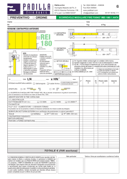
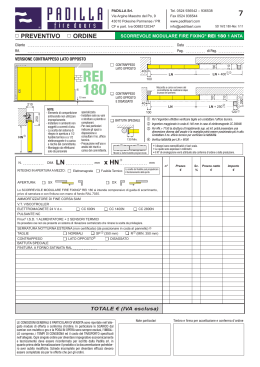
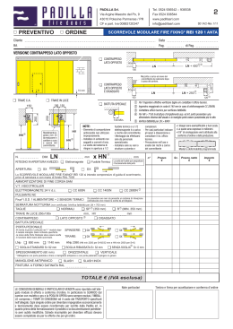
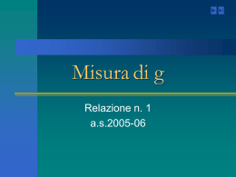
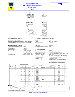
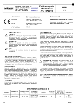
CEI SRL
TIPO N
ELETTROMAGNETI DI TRAZIONE E SPINTA PER
USO INDUSTRIALE INTENSIVO
N TYPE
PUSH–PULL SOLENOIDS
FOR INDUSTRIAL AND INTENSIVE USE
MANUALE DI ISTRUZIONI
INSTRUCTION MANUAL
Rev.1 – 01/12/10
DICHIARAZIONE DI CONFORMITA’
La C.E.I. Srl dichiara che gli elettromagneti tipo N sono conformi alle
seguenti normative:
2006/42/EC (Direttiva Europea Macchine)
2004/108/EC (Direttiva Compatibilità Elettromagnetica)
2006/95/EC (Direttiva Bassa Tensione)
e successive modifiche
L’elettromagnete è destinato ad essere incorporato per costruire una macchina e
non dev’essere messo in servizio prima che la macchina finale, nella quale
dovrà essere installato, non sia conforme alle disposizioni della Direttiva
Europea Macchine 2006/42/EC, quando applicabile.
COMPLIANCE DECLARATION
C.E.I. Srl declares the N type solenoids are in compliance with the
rules contents in:
2006/42/EC (Machinery Directive)
2004/108/EC (Electromagnetic Compatibility Standard)
2006/95/EC (Low Voltage Standard)
The solenoid is intended to be incorporated to constitute machinery and must
not be put into service until the final machinery, into which it is to be
incorporated, is according to the regulations of the EC Machinery Directive
2006/42/EC, if applicable.
Il Responsabile tecnico – The technical manager
C.E.I. Srl
Corso P. Levi, 7 - 10098 Rivoli (TO) ITALIA
Tel. 0039 011 9594446 - FAX 0039 011 9591357
E-mail: [email protected]
2
Direzione del moto
Direction of the motion
SPACCATO DELL’ELETTROMAGNETE
SOLENOID SECTION
FIG.1
FIG.2
3
ITALIANO
INTRODUZIONE
Prima della messa in funzione dell’elettromagnete, leggere attentamente il
presente libretto di istruzioni al fine di prevenire incidenti ed assicurare un
perfetto funzionamento.
Le istruzioni devono essere tenute a portata di mano e devono essere cedute
all'utente successivo in caso di vendita del pezzo.
Nel libretto di istruzioni viene usata la seguente simbologia:
PERICOLO
Questo simbolo riguarda le procedure di lavoro e di funzionamento che devono
essere rispettate attentamente per evitare pericoli all'utente o ad altre persone.
ATTENZIONE
Questo simbolo riguarda le informazioni che devono essere rispettate per
evitare danni all'apparecchio.
NOTA
Questo simbolo indica informazioni aggiuntive o consigli utili per
l’installazione.
MISURE DI SICUREZZA
La regola principale è lavorare sempre in condizioni di sicurezza per
salvaguardare la propria persona e coloro che si trovano nelle vicinanze.
In ogni caso tenere presente che questa guida è rivolta a personale qualificato,
che dispone di adeguata formazione, di attrezzature idonee e che è informato
sull’ambiente di lavoro in cui si trova ad operare. Senza la dovuta formazione
sulle procedure di lavoro e sull’uso delle attrezzature, queste ultime possono
causare danni alla persona e al prodotto.
Le indicazioni relative alla tensione di rete e al tipo di corrente riportati
nelle caratteristiche dell’elettromagnete devono corrispondere alle
caratteristiche del vostro impianto elettrico.
L’elettromagnete deve essere impiegato solamente per l'uso a cui è
destinato.
Prima della messa in funzione, assicurarsi che il connettore o il cavo di
alimentazione non sia danneggiato.
4
Non sollevare l’elettromagnete prendendolo dal connettore o dal cavo.
Scollegare l’elettromagnete prima di effettuare interventi di
manutenzione o sostituzione. E’ vietato effettuare qualsiasi variazione o
modifica senza autorizzazione.
Non montare il pezzo in ambienti con temperatura superiore a 100°C e
in presenza di fiamme libere.
DESCRIZIONE DELL’ELETTROMAGNETE (FIG.1)
L’elettromagnete in figura 1 è raffigurato in diseccitazione. In eccitazione il
nucleo mobile nr. 3 si sposta fino ad andare in battuta sul fondello nr.2.
Le parti fondamentali dell’elettromagnete sono:
1. Corpo dell’elettromagnete
2. Fondello
3. Nucleo mobile
4. Bobina
5. Soffietto protettivo (dipende dal modello)
6. Molla di ritorno (dipende dal modello)
7. Boccole DU antifrizione in metallo+polimero
8. Connettore DIN 43650 A/ISO4400 (dipende dal modello)
Su richiesta è possibile avere in alternativa i cavi di alimentazione
UTILIZZO
L’elettromagnete si deve utilizzare per azionamenti di spinta (sul lato fondello)
e di trazione (sul lato soffietto) nella direzione di scorrimento del nucleo (asse
del pezzo).
Evitare sforzi trasversali sullo stelo.
La forza indicata sulla scheda tecnica è quella di inizio corsa, che aumenta
gradualmente al diminuire della corsa (rif. grafico fig.2)
Se serve uno spostamento inferiore alla corsa massima, utilizzare la
parte finale della corsa, dove la forza è maggiore, facendo in modo che
il nucleo mobile vada sempre in battuta a fine corsa sul fondello.
5
La forza indicata sulla scheda tecnica è riferita alla temperatura ambiente di
20°C. In funzione della potenza della bobina la forza diminuisce nel tempo
all’aumentare della temperatura dell’avvolgimento. Tale calo, che può essere
anche del 30-40%, deve essere considerato nella scelta dell’elettromagnete.
Consultare il produttore per maggiori informazioni.
Anche un’elevata temperatura ambiente influenza il rendimento
dell’elettromagnete.
L’aumento della temperatura nel tempo dipende anche
dall’applicazione. In effetti se il pezzo è montato su una struttura
metallica, questa può contribuire a dissipare calore. Diversamente se è
incassato in un materiale isolante (es. legno), il solenoide può scaldarsi
rapidamente.
Servizio dell’elettromagnete
Ogni elettromagnete riporta sulla scheda tecnica il servizio (ED), dal quale
dipende la capacità di lavorare senza scaldare e danneggiarsi:
• Se l’elettromagnete è a servizio continuativo (ED 100%), non ha problemi
a rimanere eccitato a tempo indefinito.
Una temperatura esterna anche elevata, ma stabile, non è indice di
malfunzionamento.
• Se un elettromagnete non è a servizio continuativo (ED<100%), occorre
prevedere delle adeguate pause di raffreddamento tra un ciclo e l’altro per
evitare danneggiamenti dell’avvolgimento. Considerare il tempo indicativo
di 1 minuto per individuare il massimo tempo di eccitazione sul ciclo in
base al servizio dell’elettromagnete: es. ED 30% →18” ON – 42” OFF
Poiché l’aumento della temperatura nel tempo dipende anche dal
montaggio e dall’applicazione, il servizio è influenzato dalla capacità di
raffreddamento del pezzo.
La temperatura limite esterna di lavoro, che può sopportare un
elettromagnete, è di 100°C (al cuore sono già oltre 120°C).
6
MONTAGGIO DELL’ELETTROMAGNETE
•
Utilizzare per il fissaggio del pezzo i fori filettati sul fondello
Per non danneggiare la bobina interna, avvitando le viti non superare la
profondità dei fori filettati indicata sulla scheda tecnica.
Evitare di applicare sullo stelo dell’elettromagnete carichi ortogonali
all’asse del pezzo superiori a 2 Kg (19N) o sforzi radiali, poiché
possono provocare un’usura non uniforme e precoce delle boccole di
scorrimento.
•
Attaccare la leva o la parte da azionare utilizzando lo stelo mobile filettato.
L’elettromagnete ha due posizioni in eccitazione e in diseccitazione da
considerare nel registrare lo spostamento della parte da azionare.
Se serve uno spostamento inferiore alla corsa massima, utilizzare la
parte finale della corsa, dove la forza è maggiore, facendo in modo che
il nucleo mobile vada sempre in battuta a fine corsa.
•
Considerare la forza della molla, se presente, per ricavare la forza effettiva
dell’elettromagnete.
Per montaggi verticali considerare anche il peso del nucleo mobile per
avere la forza disponibile.
Non montare il pezzo accanto a fonti di calore o fiamme libere né in
luoghi eccessivamente umidi e in presenza di schizzi d’acqua.
La protezione dall’acqua e dall’umidità può essere migliorata con alcuni
accorgimenti in fase costruttiva. Consultare il produttore per maggiori
informazioni.
COLLEGAMENTO ELETTRICO
•
Utilizzare una batteria o un alimentatore adeguati alla potenza
dell’elettromagnete: verificare l’assorbimento del solenoide e la corrente
fornita dall’alimentazione
Se la tensione e la corrente sono inferiori a quelle nominali,
l’elettromagnete ha meno forza
•
Utilizzare cavi elettrici adeguati alla potenza dell’elettromagnete.
Una sezione troppo piccola, specialmente se i cavi elettrici sono molto
lunghi, può causare una caduta di tensione e danneggiamenti.
7
Collegamento al connettore DIN 43650 A/ISO4400
Per alimentare l’elettromagnete utilizzare i
due faston indicati in figura 3.
Per collegare il cavo di alimentazione al
connettore è necessario aprire il corpo del
connettore e collegare i fili positivo e
negativo sui morsetti contrassegnati con
FIG.3
“1” e “2”. Non c’è polarità da rispettare. Richiudere il corpo e fissare il
connettore all’elettromagnete con la vite in dotazione.
Su richiesta è possibile avere in alternativa i cavi di alimentazione
SPECIFICHE TECNICHE GENERALI
(altre caratteristiche dipendono dal modello)
Tensione di alimentazione:
Servizio:
Temperatura di funzionamento:
Posizione di montaggio:
Rivestimento:
Protezione:
Classe isolamento:
Livello di vibrazioni:
Livello di pressione acustica:
12V – 24V- 110V
standard ED100%
-40°C ; 100°C
orizzontale o verticale
Zincatura a norma Rohs
IP40
H (180°C)
assente
assente sotto tensione
8
RISOLUZIONE DEI PROBLEMI
La tabella che segue è un check-list per individuare i problemi più comuni. In
caso di mancata risoluzione del problema o per sostituire un solenoide
contattare la CEI.
Un singolo evento di guasto può capitare, ma quando si ripete sostituendo
il pezzo, sicuramente c’è un problema sull’applicazione: modello non
indicato o errore sistematico di montaggio.
Problema
riscontrato
Possibile causa
L’elettromagnete
non scatta
Non arriva corrente
o corrente insufficiente
L’elettromagnete
si brucia
Possibile soluzione
Verificare che la batteria o
l’alimentatore forniscano la corrente
necessaria.
Verificare il connettore o il cavo di
alimentazione
La tensione è troppo bassa Verificare che la batteria o
l’alimentatore forniscano la tensione
nominale con una tolleranza del 10%
Nel caso di cavi di alimentazione lunghi
oltre 1 m verificare che la sezione sia
adeguata alla corrente utilizzata.
La forza è insufficiente
Utilizzare un modello superiore
perché non sono stati
considerati fattori negativi
come per es. forze
d’attrito e sforzi radiali
sullo stelo
La forza prevista è
Utilizzare un modello superiore o
diminuita per l’aumento
provvedere a sistemi di raffreddamento.
della temperatura
Consultare CEI
La bobina è danneggiata
Sostituire il pezzo
dalle viti di fissaggio
Usare viti più corte (rif. scheda tecnica)
durante il montaggio
Bobina in cortocircuito
Sostituire il pezzo, riducendo il tempo in
per surriscaldamento da
eccitazione (solo servizio intermittente)
superamento limiti di
Installare un fusibile sulla linea
servizio
Bobina in cortocircuito
Sostituire il pezzo, proteggere
per penetrazione di
l’elettromagnete dall’umidità
umidità e/o acqua
Installare un fusibile sulla linea
9
ISTRUZIONI PER LO SMALTIMENTO DEL PRODOTTO
Trattasi di AEE (apparecchio elettrico o elettronico), che nel caso di
smaltimento dovrà essere dovrà essere depositato negli appositi
contenitori RAEE (rifiuti di apparecchiature elettriche ed elettroniche)
al fine di essere inviato ad una riutilizzazione ecologica (Direttiva CE
2002/96). Non disperdere nell’ambiente, non gettare il prodotto
dismesso tra i rifiuti domestici.
CONDIZIONI DI GARANZIA
La CEI garantisce la buona qualità e la buona costruzione dei materiali venduti
obbligandosi, durante il periodo di garanzia di un anno dalla data di vendita
(due anni per l’utilizzatore finale che non svolge attività professionale), a
sostituire gratuitamente nel più breve tempo possibile quelle parti che venissero
riconosciute come difettose nelle normali condizioni di lavoro, sempre che ciò
non dipenda da naturale logoramento, da guasti causati da imperizia o uso
improprio, da interventi non autorizzati, da manomissioni eseguite o fatte
eseguire dall'utilizzatore, dal caso fortuito e da condizioni di impiego non
previste a progetto o nel libretto di istruzioni.
I lavori inerenti alle riparazioni e alle sostituzioni in garanzia saranno eseguiti
presso la CEI e nulla sarà dovuto all'acquirente per eventuali spese di
manutenzione sostenute presso l’utilizzatore e per il tempo durante il quale
l'impianto o l’apparecchiatura rimarranno inoperosi.
Questa garanzia incorpora e sostituisce ogni altra garanzia legale sui difetti.
10
ENGLISH
INTRODUCTION
Please read the operating instructions carefully before using the solenoid to
prevent accidents and ensure the trouble-free operation.
Make sure you keep the instructions at hand for quick reference. If you resell
the solenoid or give it to another user, please include these instructions.
The following symbols are used in the instructions:
DANGER
This symbol draws your attention to work processes or operating procedures
that have to be carefully observed in order to prevent serious injury to the user
or another person.
CAUTION
This symbol draws your attention to information you need to ensure that your
solenoid is not damaged due to improper or careless use.
PLEASE NOTE
This symbol shows additional information or useful suggestions for the
installation.
SAFETY MEASURES
The main rule is always working under safety conditions in order to safeguard
one’s own safety and that of other bystanders.
Always remember that this guidebook is addressed to skilled personnel, having
received appropriate education and training, supplied with suitable equipment
and acquainted with the features of the working environment where they are
operating. Knowledge of working procedures and use of equipment is essential
to prevent from injury or damages possibly arising from the same equipment.
The main voltage and current type specified on the electromagnet
documentation must match the features of your electric system.
The electromagnet must only be employed for its intended use.
Before the operation, make sure that the connector or the feeding cable
is not damage.
11
Do not lift the solenoid by the connector / cable.
Disconnect the electromagnet before starting any servicing activity or
replacement. Carrying out any change or modification without prior
authorization is prohibited.
Do not assemble the part with ambient temperature higher than 100°C
or in presence of open flames.
DESCRIPTION (FIG.1)
In fig.1 the solenoid is de-energized. When it’s energized, the plunger nr.3
moves up to the fixed pole nr.2.
The important parts of the solenoid are:
1. Body of the solenoid
2. Fixed pole (bottom)
3. Plunger
4. Coil
5. Protective rubber boot (depending on the model)
6. Return spring (depending on the model)
7. Metal-polymer bearing DU
8. Electrical connector DIN 43650 A/ISO4400 (depending on the model)
Upon request power cables can be supplied
APPLICATIONS
The electromagnet must be used for push (bottom side) and pull (boot side)
operations in the direction of sliding of the plunger (axis of the piece).
Avoid cross stresses on the rod: any misalignment causes friction and a
force reduction.
The force value in the table is the initial stroking force, which gradually
increases as the stroke decreases (see the graph on the fig.2)
When a displacement shorter than the maximum stroke is required, use
the final length of the stroke, where the force is highest, still making the
plunger strike against the bottom plate at end of stroke.
12
Influence of temperature
The force indicated in the technical sheet refers to an environment temperature
of 20°C. If a cycle is repeated several times, according to the power of the coil,
force decreases over time as the winding temperature increases. This decrease,
that may be even 30-40%, is to be considered when choosing the
electromagnet. Contact the manufacturer to have more information.
Also a high environment temperature has influence on the
electromagnet performance
Increase in temperature over time also depends on the application. If the
part is mounted on a metal structure, this can contribute to disperse heat.
Otherwise if it is embedded in insulating material (e.g. wood) the
solenoid can heat rapidly.
Electromagnet operation
The technical sheet for each electromagnet indicates the operating capacity
(ED), according to which it can operate without becoming heated or damaged:
• If the electromagnet is in continuous duty (ED 100%), it can remain excited
for an indefinite time.
A high, but stable external temperature is not an indication for
malfunctioning.
•
If an electromagnet is in intermittent duty (ED<100%), appropriate cooling
pauses are to be provided between one cycle and the next to avoid damage
to the winding. Consider an indicative time of 1 minute to identify the
maximum excitation time on the cycle according to electromagnet
operation: e.g.. ED 30% →18” ON – 42” OFF
Since increase in temperature over time depends also on assembly and
application, operation is influenced by the part cooling capacity.
The external working temperature limit that an electromagnet can
sustain is 100°C (core temperature will be over 120°C).
13
ELECTROMAGNET ASSEMBLY
•
Use the threaded holes on the bottom to the fixing of the piece.
In order to do not damage the internal coil with the screws, keep to the
depth of the holes specified in the data sheet.
Avoid cross stresses on the rod greater than 2 Kg (19N), because they
could cause an irregular and quick wear of the bearings.
•
Join the lever or the part to move to the threaded stem. The electromagnet
energized and de-energized has two positions to consider in the adjustment
of the movement of the lever.
When a displacement shorter than the maximum stroke is required, use
the final length of the stroke, where the force is highest, still making the
plunger strike against the bottom plate at end of stroke.
•
Consider the force of the spring, if present, to get the effective force of the
solenoid.
The choice of the spring is important as it has to be a compromise
between the electromagnet force, from which the force of the mounted
spring has to be deducted, and the force of the spring, required to make
the lever return on de-energizing.
For vertical assembly, consider also the weight of the plunger to get the
available force value.
Do not mount the part on hot surfaces (T>100°C), close to open
flames or in excessively damp places or where water squirts are
possible.
The protection from water and moisture may be improved by taking
some measures on construction. For further details, please consult the
manufacturer.
14
ELECTRICAL CONNECTION
Use a battery or a power supply suitable to the electromagnet power rating:
check the Elettrostart current and the current supplied.
If voltage and current are lower than the rated values, also the force of
the electromagnet is lower.
A correct use of the power cables (right gauge and length) reduces the voltage
losses. Therefore, a suitable cable gauge has to be selected and the distance
from the energy source (power supply or battery) has to be adequate.
A cross-section too small, especially if the electrical cables are very
long, could cause a fall of voltage and damages.
Connection of DIN 43650 A/ISO4400 connector
To power the electromagnet use the two
faston connectors indicated in fig. 3.
To connect the power supply cable to
the connector, open the connector
casing and connect the positive and
negative wires on the terminals marked
FIG.3
“1” and “2”. No polarity to respect. Close the casing and fasten the connector
with the screw supplied.
Upon request power cables can be supplied
TECHNICAL DATA
(other specifications depend on the model)
Voltage supply:
Duty ED:
Ambient temperature:
Fitting position:
Treatment :
Protection type:
Insulation class:
Vibration level:
Noise level:
12V – 24V- 110V
standard 100%
-40° to 100°C
vertical or horizontal
zinc-plating Rohs conform
IP40
H (180°C)
none
none
15
SOLUTION OF TROUBLES
The following table is a check-list useful to identify the most common troubles.
Should it not be possible to solve problems or to replace a solenoid, please
contact CEI.
A single failing event may occur, however when it recurs after the part
has been replaced, it is certain that a problem exists on the application, as
e.g. unsuitable part model or systematic assembly error.
Detected trouble Possible cause
The
electromagnet
does not move
Electric current
failure or current
inadequate
Too low voltage
The solenoid is
burnt
The force is
inadequate: some
negative factors as
friction force or
radial stresses
applied to the rod,
have not been
considered.
The expected force
has fallen due to an
increase in the
operative
temperature
The fixing screws
have damaged the
coil during the
assemblage
Short-circuit of the
coil for
overheating for
exceeding the duty
limits
Short-circuit of the
coil for penetration
of damp or water
Possible solution
Check the power cables are properly connected
.
Check that the battery or power supply feed
with the required current
Check that the battery or power supply provide
the rated voltage with 10% tolerance.
In case of long power cables, verify that their
gauge is suitable for the voltage applied
Use a more powerful model.
Use a more powerful model.
Add an additional cooling system
Please contact CEI.
Replace the piece and use shorter screws (ref.
technical card)
Replace the piece, reducing the time ON energized coil (only intermittent duty)
Add a fuse on the feeding line.
Replace the piece.
Protect the solenoid from the water and damp
Add a fuse on the feeding line.
16
INSTRUCTIONS FOR DISPOSAL
This article is classified as EEE (electrical and electronic equipment)
and must therefore be disposed of in the appropriate recycling
receptacles of WEEE (waste electrical and electronic equipment) and
sent for recovery in an environmentally friendly manner (European
Directive 2002/96EC). Do not dispose of electrical and electronic
equipment in the environment or in household waste.
WARRANTY CONDITIONS
CEI guarantees good quality and good conditions of materials sold, with the
obligation, during the warranty period of one year from the date of sale to
replace free of charge in the shortest time possible any parts acknowledged as
faulty under normal working conditions, providing this is not caused by natural
wear, failures caused by incompetency or improper use, by unauthorised
interventions, by tampering carried out or authorised by the user, by fortuitous
events and/or conditions of use not foreseen by the design or in the instructions
handbook.
Work regarding repairs and replacement of parts under warranty shall be
carried out in the works of CEI and there shall be nothing due to the purchaser
for any maintenance costs sustained by the user and for the time in which the
system or equipment shall remain inoperative.
This warranty incorporates ands replaces any other legal guarantee concerning
defects.
17
C.E.I. SRL
COSTRUZIONI ELETTROMAGNETICHE INDUSTRIALI
Corso P. Levi, 7 - 10098 – Rivoli (TO) - ITALY
Tel.: 0039 011 9594446 - FAX 0039 011 9591357
www.cei–italy.it
e-mail: [email protected]
[email protected]
18
Scaricare