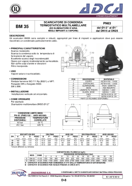
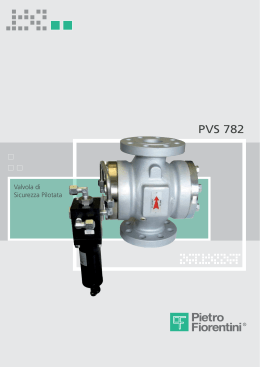
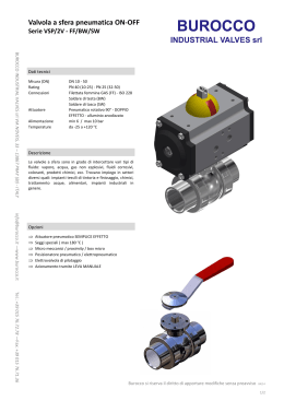
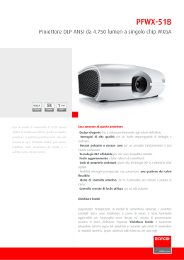
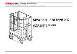
> > >
OBL Metering Pumps
MD
Mechanical diaphragm metering pumps
BLACKPLUS
series
Pompe dosatrici a membrana meccanica
D_MD_GB.IT_03 ‘09
The OBL MD series are mechanical diaphragm spring
return mechanism metering pumps. They combine
the working characteristics of a plunger with the
sealing advantages of a diaphragm pump.
Thanks to the quality and simple design of the
diaphragm, these pumps are easy-handling.
La pompa dosatrice OBL a membrana meccanica serie
MD con meccanismo a ritorno a molla con albero
eccentrico e disco di spinta, associa le caratteristiche
funzionali delle pompe a pistone e i vantaggi delle
pompe a membrana.
Grazie alla qualità e alla semplicità della membrana
queste pompe sono di facile gestione.
MD
Threaded MD metering pump with PP heads. Threaded connections.
Pompa multipla tipo MD con testate in PP. Attacchi filettati.
Mechanical diaphragm metering pumps
Pompa dosatice a membrana meccanica
For motor characteristics see page 5.
Per le caratteristiche del motore vedi pag. 5.
Standard manual adjustment.
Regolazione manuale standard.
Black anodizing aluminium casing.
Corpo meccanismo in alluminio con
ossidazione anodica nera.
PTFE coated cast iron
diaphragm chamber.
Camera membrana
in ghisa teflonata.
1
PVC pump head.
Testata pompante in PVC .
> > > OBL Metering Pumps
MD
BLACKPLUS
series
General features:
• Diaphragm, low cost, robust, compact metering pump.
• The mechanical diaphragm works both giving the
swept volume, acting basically as plunger, and as separator between casing and the pumped fluid.
• Easy and minimum maintenance required, thanks to
the reduced number of components.
• The OBL’s unique (patented) mechanical diaphragm
design ensures linearity between flow rate and percentage of stroke. The flow rate is virtually uneffected by
the working pressure variations.
• Leak-free pump, due to OBL’s stress-proof diaphragm.
• High working safety:
- No external moving parts.
- Leak-free operations.
AISI 316L head wetted end MD pump with ZCA electrical actuator.
Pompa tipo MD con testata in AISI 316L e servocomando Obl ZCA.
• Max suction lift 1,5 m.w.c. (see operating manual).
Caratteristiche generali:
• PTFE coated cast iron diaphragm chamber
chemically resistant to acid fumes.
• Pompa a membrana economica, robusta e compatta.
• La membrana meccanica svolge il duplice ruolo di trasmissione della cilindrata, agendo in pratica come un pistone, e di separatore tra manovellismo e fluido da pompare.
• Manutenzione semplice e ridotta al minimo, grazie al
basso numero di componenti.
• La particolare struttura fisica della membrana meccanica
OBL (brevetto depositato) assicura una proporzionalità lineare fra portata e percentuale di regolazione. La portata risulta
quasi insensibile alle variazioni di pressione d’esercizio.
• Leak-free diaphragm pump head.
• Smooth and linear adjustment, either stationary or
running, via micrometer knob.
• Compliance to ATEX STD (94/9/CE), group II,
category 3 (zone 2/22).
• Supporto della testata pompante realizzato in ghisa
teflonata resistente ad ambienti acidi e riducenti.
• Perfetta tenuta idraulica grazie all’elasticità della
membrana.
• Testata a membrana a tenuta stagna dal liquido pompato.
• Sicurezza operativa grazie all’assenza di perdite del
liquido dosato e di organi esterni in movimento.
• Regolazione continua della portata sia a pompa ferma
che in moto, tramite manopola graduata.
• Aspirazione max 1,5 mt. colonna acqua (vedi libretto
istruzioni).
• Conforme alla normativa ATEX (94/9/CE), gruppo II,
categoria 3 (zona di pericolo 2/22).
MATERIALS OF CONSTRUTIONS
MATERIALI DI COSTRUZIONE
PARTS/PARTICOLARI
LIQUID END/CORPO TESTATA
VALVE GUIDE/GUIDA VALVOLA
VALVE SEAT/SEDE VALVOLA
VALVE/VALVOLA
VALVE SEAL/TENUTA VALVOLA
VALVE HOUSING/CONT. VALVOLA
DIAPHRAGM/MEMBRANA
FLANGE/FLANGIA
PP
PP11
PP32
S
T
A
P
PP
PP
PVC
PIREX
VITON (FPM)
SV PP / DV PVC
TEFLON (PTFE)
PVC
PP
PP
AISI 316L
AISI 316L
VITON (FPM)
SV PP / DV PVC
TEFLON (PTFE)
PVC
PP
PP
INCOLOY 825
HASTELLOY C-276
VITON (FPM)
SV PP / DV PVC
TEFLON (PTFE)
PVC
PVDF
PVDF
PVDF
PYREX/CERAMIC
VITON (FPM)
PVDF
TEFLON (PTFE)
PVDF
TEFLON (PTFE)
TEFLON (PTFE)
TEFLON (PTFE)
PTFE/CERAMIC
VITON (FPM)
TEFLON (PTFE)
TEFLON (PTFE)
TEFLON (PTFE)
AISI 316L
PP/AISI 316L VM
AISI 316L
AISI 316L
VITON (FPM)
AISI 316L
TEFLON (PTFE)
AISI 316L
PVC
PP
PVC
PYREX/CERAMIC
VITON (FPM)
PVC
TEFLON (PTFE)
PVC
2
Basic modelsdiaphragm metering pumps
MD Mechanical
• Double and single valve ball.
• Suction and discharge connections both threaded
and flanged (on demand).
• Max. suction lift 1,5 m.w.c. (see operating manual).
• Max. temperature of dosed chemical: 45 °C.
• ± 2% accuracy within 10 to 100% of the nominal flow rate.
• L'esecuzione prevede valvole a sfera doppie e singole.
• Gli attacchi di aspirazione e mandata sono forniti sia
filettati che flangiati.
• Aspirazione massima 1,5 mt. colonna acqua
(vedi libretto istruzioni).
• Temperatura massima del liquido dosato: 45 °C.
• Precisione ± 2% tra il 10 ed il 100% della portata di targa.
Pompe dosatrice a membrana meccanica
Pump/Pompa:
• Preset for multiple heads
Modello predisposto per
pompe multiple
Adjustm./Regolaz.:
• Via micrometer knob
Manopola con nonio lineare
Material/Materiale: • PTFE coated cast iron diaphragm
Camera membrana:
ghisa verniciata con PTFE
Strokes/1'-Colpi/1’:
• 50Hz > 36-50-70-95-115-155
60Hz > 30-43-60-84-118-138
Stroke/Corsa:
• 1/6 mm.
Weigth/Peso:
• 17÷30 Kgs/Kg
MD
Sectional view
Sezione
PP head. “PP” execution.
Testata in polipropilene. Esecuzione “PP”.
AISI 316L head. “A” execution.
Testata inAISI 316L. Esecuzione “A”.
3
> > > OBL Metering Pumps
Diaphragm structure
Modelli
base
Struttura della
membrana
Max overall dimensions
Dimensioni massime di ingombro
Manual adjustment / Regolazione manuale
The OBL's unique (patented) mechanical diaphragm design ensures controlled volumetric displacement, giving plunger-like performances.
Thus the flow rate is virtually unaffected by the working pressure variations.
384 mm.
La particolare struttura fisica della membrana meccanica OBL (brevetto depositato), consente una flessione controllata e permette alla membrana un comportamento analogo al pistone. In questo modo la portata diventa quasi
insensibile alle variazioni della pressione di esercizio della pompa.
300 mm.
180 mm.
Automatic adjustment via electrical actuators
484 mm.
Regolazione automatica tramite servocomando elettrico
100 mm.
Diaphragm sectional view
250 mm.
Sezione della membrana
Sectional view without plastic support ring.
Sezione senza anello di supporto.
620 mm.
Complete sectional view with plastic support ring.
Sezione completa con anello di supporto della membrana.
Flow rate linearity
Linearità di portata
An OBL mechanical diaphragm pump has the
same linearity as a plunger pump. The diagram
on the left shows the linearity between flow
rate and percentage of stroke.
Il funzionamento della membrana meccanica
OBL rispecchia la linearità di portata di una
pompa a pistone.
Tale particolarità è evidenziata in questo diagramma di portata . Dall’andamento delle linee
di portata è evidente la proporzionalità lineare
fra portata e regolazione.
Detail of the bonding between diaphragm and metallic support
Ancoraggio della mmembrana al supporto metallico
Cross-section of the diaphragm
Sezione della membrana.
PRESS. 0,5 BAR
PRESS. 1,5 BAR
PRESS. 6 BAR
Flow rate l/h / Portata l/h
200
METALLIC SUPPORT
SUPPORTO METALLICO
150
PTFE/TEFLON
RUBBER/GOMMA
PTFE/TEFLON
100
GOMMA /RUBBER
NYLON NET/RETE
50
0
25%
50%
75%
100%
Adjustment % / Regolazione%
4
MD Technical data
MAX FLOW RATE l/h
PORTATA Max l/h
PRESS.MAX BAR
PRESS. MAX bar
MD1
MD1,6
MD2,4
MD3,5
MD4
MD5,5
36
50
70
95
115
155
1
1,5
2,4
3,5
4
5,5
10
10
10
10
10
10
1/4”
1/4”
1/4”
1/4”
1/4”
1/4”
g.f.g.f.g.f.g.f.g.f.g.f.-
BSPF
BSPF
BSPF
BSPF
BSPF
BSPF
DN15-1/2”ANSI 150#RF
DN15-1/2”ANSI 150#RF
DN15-1/2”ANSI 150#RF
DN15-1/2”ANSI 150#RF
DN15-1/2”ANSI 150#RF
DN15-1/2”ANSI 150#RF
2
2
2
2
2
2
65
65
65
65
65
65
MD3,1
MD4,5
MD7,1
MD8,5
MD10,5
MD13
36
50
70
95
115
155
3
4,5
7
8,5
10
13
10
10
10
10
10
10
1/4”
1/4”
1/4”
1/4”
1/4”
1/4”
g.f.g.f.g.f.g.f.g.f.g.f.-
BSPF
BSPF
BSPF
BSPF
BSPF
BSPF
DN15-1/2”ANSI 150#RF
DN15-1/2”ANSI 150#RF
DN15-1/2”ANSI 150#RF
DN15-1/2”ANSI 150#RF
DN15-1/2”ANSI 150#RF
DN15-1/2”ANSI 150#RF
2
2
2
2
2
2
94
94
94
94
94
94
MD11
MD16
MD23
MD31
MD37
MD50
36
50
70
95
115
155
11
16
23
31
37
50
10
10
10
10
10
10
1/4”
1/4”
3/8”
3/8”
3/8”
3/8”
g.f.g.f.g.f.g.f.g.f.g.f.-
BSPF
BSPF
BSPF
BSPF
BSPF
BSPF
DN15-1/2”ANSI 150#RF
DN15-1/2”ANSI 150#RF
DN15-1/2”ANSI 150#RF
DN15-1/2”ANSI 150#RF
DN15-1/2”ANSI 150#RF
DN15-1/2”ANSI 150#RF
4
4
4
4
4
4
108
108
108
108
108
108
MD35
MD49
MD75
MD101
MD120
MD155
36
50
70
95
115
155
35
49
75
101
120
155
10
10
10
10
10
10
3/8” g.f.- BSPF
3/8” g.f.- BSPF
3/8” g.f.- BSPF
3/8” g.f.- BSPF
3/8”g.f.BSPF 1/2”g.f.BSPF
3/8”g.f.BSPF 1/2”g.f.BSPF
DN15-1/2”ANSI 150#RF
DN15-1/2”ANSI 150#RF
DN15-1/2”ANSI 150#RF
DN15-1/2”ANSI 150#RF
DN15-1/2”ANSI 150#RF
DN15-1/2”ANSI 150#RF
6
6
6
6
6
6
138
138
138
138
138
138
MD102
MD131
MD201
MD261
MD321
MD421
36
50
70
95
115
155
100
132
197
260
320
420
7
7
6
6
5
5
3/4” g.f.- BSPF
3/4” g.f.- BSPF
3/4” g.f.- BSPF
3/4” g.f.- BSPF
1” g.f.- BSPF
1” g.f.- BSPF
DN20-3/4”ANSI 150#RF
DN20-3/4”ANSI 150#RF
DN20-3/4”ANSI 150#RF
DN20-3/4”ANSI 150#RF
DN25-1”ANSI 150#RF
DN25-1”ANSI 150#RF
6
6
6
6
6
165
165
165
165
165
MD150
MD190
MD301
MD431
MD521
36
50
70
95
115
150
200
300
435
520
5
5
5
5
5
1”
1”
1”
1”
1”
1
1
1
1
1
65
65
65
65
65
MD0,8
MD1,2
MD2,9
MD4,2
MD4,8
30
43
84
118
138
0,8
1,2
2,9
4,2
4,8
10
10
10
10
10
1/4”
1/4”
1/4”
1/4”
1/4”
g.f.g.f.g.f.g.f.g.f.-
BSPF
BSPF
BSPF
BSPF
BSPF
DN15-1/2”ANSI 150#RF
DN15-1/2”ANSI 150#RF
DN15-1/2”ANSI 150#RF
DN15-1/2”ANSI 150#RF
DN15-1/2”ANSI 150#RF
2
2
2
2
2
65
65
65
65
65
MD2,6
MD3,9
MD8,4
MD10,2
MD12
30
43
84
118
138
2,6
3,9
8,4
10,2
12
10
10
10
10
10
1/4”
1/4”
1/4”
1/4”
1/4”
g.f.g.f.g.f.g.f.g.f.-
BSPF
BSPF
BSPF
BSPF
BSPF
DN15-1/2”ANSI 150#RF
DN15-1/2”ANSI 150#RF
DN15-1/2”ANSI 150#RF
DN15-1/2”ANSI 150#RF
DN15-1/2”ANSI 150#RF
2
2
2
2
2
94
94
94
94
94
MD9
MD14
MD28
MD36
MD45
30
43
84
118
138
9
14
28
36
45
10
10
10
10
10
1/4”
1/4”
3/8”
3/8”
3/8”
g.f.g.f.g.f.g.f.g.f.-
BSPF
BSPF
BSPF
BSPF
BSPF
DN15-1/2”ANSI 150#RF
DN15-1/2”ANSI 150#RF
DN15-1/2”ANSI 150#RF
DN15-1/2”ANSI 150#RF
DN15-1/2”ANSI 150#RF
4
4
4
4
4
108
108
108
108
108
MD42
MD58
MD90
MD121
MD145
43
60
84
118
138
42
58
90
121
145
10
10
10
10
10
3/8” g.f.- BSPF DN15-1/2”ANSI 150#RF
3/8” g.f.- BSPF DN15-1/2”ANSI 150#RF
3/8” g.f.- BSPF DN15-1/2”ANSI 150#RF MODEL NUMBER
3/8”g.f.BSPF 1/2”g.f.BSPF DN15-1/2”ANSI 150#RF
3/8”g.f.BSPF 1/2”g.f.BSPF DN15-1/2”ANSI 150#RF
6
6
6
6
6
138
138
138
138
138
MD119
MD158
MD236
MD312
MD384
43
60
84
118
138
120
158
236
312
384
7
6
6
5
5
3/4” g.f.- BSPF
3/4” g.f.- BSPF
3/4” g.f.- BSPF
1” g.f.- BSPF
1” g.f.- BSPF
6
6
6
6
165
165
165
165
MD180
MD228
MD360
MD519
43
60
84
118
165
228
350
515
5
5
5
5
TYPE
TIPO
65
65
65
65
65
65
ø DIAPHRAGM
ø MEMBRANA
1
1
1
1
1
1
STROKE LENGHT
CORSA
STROKES /1’
COLPI AL 1’
Caratteristiche tecniche
CONNECTIONS/ATTACCHI
THREADED
FILETTATI
PP
A
FLANGED
FLANGIATI
PP
A
50 Hz
g.f.g.f.g.f.g.f.g.f.-
BSPF
BSPF
BSPF
BSPF
BSPF
DN25-1”ANSI 150#RF
DN25-1”ANSI 150#RF
DN25-1”ANSI 150#RF
DN25-1”ANSI 150#RF
DN25-1”ANSI 150#RF
60 Hz
5
1”
1”
1”
1”
g.f.g.f.g.f.g.f.-
BSPF
BSPF
BSPF
BSPF
DN20- /4”ANSI 150#RF
DN20-3/4”ANSI 150#RF
DN20-3/4”ANSI 150#RF
DN25-1”ANSI 150#RF
DN25-1”ANSI 150#RF
ATEX rated MD with
manual adjustment via
1/% step dial handwheel.
Pompa MD in versione ATEX
con regolazione tramite
orologio gravitazionale.
Portate/Flow rates: •
•
•
•
Motori/Motors:
• Trifase /Threephase 0,37 kW 4 poli /poles - IP55 - CL F - IEC 34-1
Motore standard/Std motor 71-B14
- 230÷400 V - 3 - 50 Hz
- 440÷480 V - 3 - 60 Hz
• Monofase /Singlephase
- 4 poli /poles - IP55 - CL F - IEC 38-1
Motore standard/Std motor 71-B14
220÷240 V - 50 Hz - 0,37 kW
110÷115 V - 50 Hz - 0,37 kW
220÷230 V - 60 Hz - 0,37 kW
110÷115 V - 60 Hz - 0,37 kW
ESEMPIO COMPOSIZIONE SIGLA
KEY TO SYMBOL
LEGENDA
POMPA TIPO / PUMP MODEL
3
DN25-1”ANSI 150#RF
DN25-1”ANSI 150#RF
DN25-1”ANSI 150#RF
DN25-1”ANSI 150#RF
1÷13 L/h (corsa/stroke lenght 1-2mm.)
11÷50 L/h (corsa/stroke lenght 2mm.)
35÷155 L/h (corsa/stroke lenght 4mm.)
102÷521 L/h (corsa/stroke lenght 6mm.)
PORTATA l/h / FLOW RATE l/h
MD 521 PP F Z
PP
ESECUZIONE POLIPROPILENE / PP CONSTRUCTION
A
ESECUZIONE AISI-316L / AISI-316L CONSTRUCTION
PP11
ESEC. PP+VALVOLA E SEDE IN AISI-316L /PP CONSTRUCTION+AISI-316L VALVE AND SEAT
PP32
P/S/T
ESECUZIONE PP+VALVOLA HASTELLOY C - SEDE INCOLOY 825
PP CONSTRUCTION + HASTELLOY C VALVE - INCOLOY 825 SEAT
Z
SERVOCOMANDO ELETTRICO OBL 4÷20 mA / OBL 4÷20 mA ELECTRIC ACTUATOR
W
SERVOCOMANDO PNEUMATICO 3÷15 PSI / 3÷15 PSI PNEUMATIC ACTUATOR
F
ATTACCHI FLANGIATI UNI-DIN / UNI-DIN FLANGED CONNECTIONS
FA
ATTACCHI FLANGIATI ANSI /ANSI FLANGED CONNECTIONS
> > > OBL Metering Pumps
MD Adjustment systems
Manual adjustment
Regolazione manuale >
Sistemi di regolazione
Knob with micrometer scale.
Manopola e nonio lineare.
0÷100% manual adjustment via:
• Knob with micrometer scale (as standard).
• Dial handwheel (on demand).
Flow rate adjustment is smooth and linear, and can be made whether
the pump is running or stationary.
The dial adjuster has a 0÷100% scale for accurate reading.
La regolazione della portata è in percentuale da 0% a 100% della
portata max. di targa:
• Con manopola e nonio lineare (STD).
• Con indicatore tipo orologio (su richiesta).
Dial handwheel.
Indicatore tipo orologio.
La regolazione della portata è continua e regolare, può essere effettuata
sia a pompa ferma che in moto. Il quadrante ha una scala con percentuale
per un’accurata lettura da 0 a 100%.
< Electric actuator
Servocomando elettrico
MD series can be equipped with Z type electrical actuator, with following
characteristics:
• IP 66 STD
• Manual emergency override
• Anticondensation heater (on demand)
• Non standard voltages and frequencies
• External automatic/manual selector
Flow rate is adjusted according to following input signals:
• 4-20 mA, 0-20 A, 20-4 mA e 0-10 V
• Pulses (0÷2 Hz - 0÷30 Hz)
• RS 485 protocol
• Profibus DP - VØ
Le MD possono essere fornite con servocomando elettrico tipo Z avente le
seguenti caratteristiche:
• IP 66 standard
• Regolazione manuale d’emergenza
• Resistenza anticondensa (su richiesta)
• Frequenze e tensioni non STD
• Selettore esterno automatico/manuale
La regolazione della portata avviene in funzione dei seguenti segnali regolanti:
• 4-20 mA, 0-20 mA, 20-4 mA e 0-10 V
• Impulsi (0÷2 Hz - 0÷30 Hz)
• Protocollo di comunicazione RS 485
• Profibus DP - VØ
3÷15 PSI Pneumatic actuator
Servocomando pneumatico >
• Pneumatic actuator type W.
• Air instrument 3÷15 PSI
• Air supply 4-6 bar
• Servocomando pneumatico tipo W.
• Aria strumenti 3÷15 PSI
• Aria potenza 4-6 bar
6
Technical data are subject to modifications without prior notice. - I dati tecnici possono essere modificati senza preavviso.
> > Studio_SCAFIDI_ComunicAzioni_Visive
> > > OBL Metering Pumps
OBL s.r.l.
20090 Segrate - MILANO
Via Kennedy, 12
Tel. +39-02.269191
Fax +39-02.2133893
[email protected]
www.obl.it
MD
BLACKPLUS
series
Scaricare