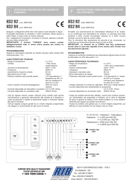
I
ISTRUZIONI AGGIUNTIVE PER QUADRI DI COMANDO:
F
INSTRUCTIONS COMPLÉMENTAIRES POUR LES COFFRETS:
KS2 R2 (cod. ABKS160)
KS2 R4 (cod. ABKS162)
KS2 R2 (code ABKS160)
KS2 R4 (code ABKS162)
Eseguire i collegamenti della rete e del motore come descritto in figura.
È possibile alimentare la centralina a 230V monofase, trifase oppure a 400V trifase, in base
al tipo di motore utilizzato.
Per i collegamenti di accessori, sicurezze e comandi, attenersi al libretto istruzioni della
scheda KS2.
IMPORTANTE: Il trimmer “TORQUE” deve essere ruotato obbligatoriamente tutto in
senso orario (questo per evitare un fastidioso ronzio).
Procéder aux branchements de l’alimentation électrique et du moteur en se conformant aux
descriptions du schéma.
-Le panneau peut être alimenté à 230V courant monophasé, triphasé ou à 400V courant
triphasé, suivant le type de moteur utilisé.
Pour la connexion des accessoires de sécurité et de commande, se conformer aux
instructions figurant dans le livret du KS2.
IMPORTANT: Le trimmer TORQUE (FORCE) doit être entièrement tourné dans le sens
des aiguilles d’une montre (afin d’éviter tout bourdonnement gênant).
PROGRAMMAZIONE
Seguite le informazioni descritte sul libretto istruzioni della scheda KS2 (microinterruttori
1-2).
CARATTERISTICHE TECNICHE
- Range di temperatura - Umidita - Tensione di alimentazione - Frequenza - Assorbimento massimo scheda - Microinterruzioni di rete - Potenza massima spia cancello aperto
0 ± 70°C
< 95% senza condensazione
230V~ ±10%
50/60 Hz
60 mA
100ms
3 W (equivalente a 1 lampadina da
3W o 5 led con resistenza in serie da
2,2 Kohm)
- Carico massimo all’uscita lampeggiatore40W con carico resistivo
- Corrente disponibile per fotocellule e accessori 0,4 A ±15% 24Vac
- Corrente disponibile su connettore radio
200mA 24Vac
- Tutti gli ingressi devono essere utilizzati come contatti puliti perché l’alimentazione è
generata internamente alla scheda ed è disposta in modo da garantire il rispetto di
isolamento doppio o rinforzato rispetto alle parti in tensione.
- Tutti gli ingressi vengono gestiti da un circuito integrato programmato che esegue un
autocontrollo ad ogni avvio di marcia.
PROGRAMMATION
Toujours se conformer strictement aux informations figurant dans le livret de fabrication du
KS2 (dip-switch 1-2).
CARACTÉRISTIQUES TECHNIQUES
- Plages de température
- Humidité
- Tension d’alimentation
- Fréquence
- Absorption maximale carte
- Micro-interrupteurs de réseau
- Puissance maximale voyant portail ouvert
0 ± 70°C
< 95% sans condensation
230V~ ±10%
50/60 Hz
60 mA
100mS
3 W (équivalant à 1 lampe de
3W ou 5 voyants lumineux avec
résistance en série de 2,2 Kohm)
- Charge maximale à la sortie feu clignotant
40W avec charge résistive
- Courant disponible pour photocellules et accessoires 0,4 A ±15% 24Vac
200mA 24Vac
- Courant disponible sur connecteur radio
- Toutes les entrées doivent être utilisées comme des contacts propres, car l’alimentation
est engendrée à l’intérieur de la carte et disposée de façon à garantir le respect d’une
double isolation ou d’une isolation renforcée par rapport aux parties sous tension.
- Toutes les entrées sont gérées par un circuit intégré programmé, qui effectue un autocontrôle lors de chaque mise en route.
T1-T2-T3-T4 = Teleruttori - Telerutteurs
Teleruttori => 4 KW per KS2 R2,
=> 5,5 KW per KS2 R4
Telerutteurs => 4KW pour KS2 R2
=> 5,5KW pour KS2 R4
Questo prodotto è stato completamente progettato e costruito in Italia · Ce produit a été complètement développé et fabriqué en Italie · This
product has been completely developed and built in Italy · Artìculo totalmente proyectado y producido en Italia
®
automatismi per cancelli
automatic entry systems
25014 CASTENEDOLO (BS) - ITALY
Via Matteotti, 162
Tel. +39.030.2135811
Fax +39.030.21358279
www.ribind.it - [email protected]
G
B
ADDITIONAL INSTRUCTIONS FOR CONTROL BOARDS:
D
ZUSÄTZLICHE ANLEITUNGEN FÜR DIE STEUERUNGEN:
KS2 R2 (code ABKS160)
KS2 R4 (code ABKS162)
KS2 R2 (Kode ABKS160)
KS2 R4 (Kode ABKS162)
Execute the connections of the powez supply and of the motor as described in the scheme.
It is possible to feed the board at 230V 1-phase, 3-phase or at 400V 3-phase, based on
the type of motor used.
To connect safety and command accessories follow the KS instructions booklet.
IMPORTANT: The TORQUE trimmer must be turned completely in clockwise sense (in
order to avoid an annoying buzz).
Die Verbindungen zur Stromspeisung und zum Motor wie im Schema beschrieben
ausführen.
Die Schalttafel kann mit 230V einphasig, dreiphasig oder 400V dreiphasig gespeist werden,
je nach angewendetem Motortyp.
Um das Sicherheits- und Steuerzubehör anzuschließen, den Anleitungen des KS2Handbuches folgen.
WICHTIG: Der Trimmer der TORQUE (KRAFT) muss vollständig im Uhrzeigersinn
gedreht sein (um ein störendes Geräusch zu vermeiden).
PROGRAMMING
Follow the informations described on the KS2 instructions booklet (dip-switches 1-2).
TECHNICAL CHARACTERISTICS
- Range of temperature 0 ± 70°C
- Moisture < 95% without condensation
- Power supply voltage 230V~ ±10%
- Frequency 50/60 Hz
- Max. power consumption of the card 60 mA
100ms
- Transient power mains drops - Max. capacity of the warning light - gate open3 W (corresponding to one 3W
lamp or to 5 LEDS with 2,2 Kohm
resistance in series)
- Max. load at blinker output 40W with resistive load
- Available current for photocells and accessories 0,4 To ±15% 24Vac
200mA 24Vac
- Available current for the radio connector - All inputs must be used as clean contacts without being earthed, because power supplied
is generated In the card and is arranged so as to allow for double or reinforced Insulation
with respect to live parts.
- All inputs are controlled by a programmed integrated circuit, that carries out a self-control
cycle every time the gate is operated.
PROGRAMMIERUNG
Halten Sie sich an die Informationen des KS2-Handbuches (dip-switch 1-2).
TECHNISCHE EIGENSCHAFTEN
- Temperaturbereich
0 ± 70°C
- Feuchtigkeit
< 95% ohne Kondensation
- Versorgungsspannung
230V~ ±10%
50/60 Hz
- Frequenz
- Max. Stromaufnahme Karte
60 mA
- Netz-Mikroschalter
100mS
- Maximale Leistung der Kontrollleuchte für Tor offnen 3 W (gleichwertig einer Lampe
mit 3W oder 5 LEDs mit einem
Reihenwiderstand von 2,2 Kohm)
- Maximale Last am Blinkerausgang 40W mit ohmscher Last
- Verfügbarer Strom für Fotozellen und Zubehör 0,4 A ±15% 24Vac
- Verfügbarer Strom am Radioverbinder 200mA 24Vac
- Alle Eingänge müssen als Kontakte nicht zur Erdung ausgeführt sein, da die Versorgung
intern an der Karte generiert wird und diese so angeordnet ist, dass eine doppelte oder
verstärkte Isolierung gegenüber spannungsführender Teile garantiert wird.
- Alle Eingänge werden von einem programmierten integrierten Schaltkreis verwaltet, der
bei jeder Inbetriebnahme eine automatische Kontrolle durchführt.
Questo prodotto è stato completamente progettato e costruito in Italia · Ce produit a été complètement développé et fabriqué en Italie · This
product has been completely developed and built in Italy · Artìculo totalmente proyectado y producido en Italia
®
automatismi per cancelli
automatic entry systems
25014 CASTENEDOLO (BS) - ITALY
Via Matteotti, 162
Tel. +39.030.2135811
Fax +39.030.21358279
www.ribind.it - [email protected]
Cod. CVA1512 - 26092014 - Rev. 02
T1-T2-T3-T4 = Teleruptors - Schütze
Teleruptors => 4KW for KS2 R2
=> 5,5KW for KS2 R4
Schütze
=> 4KW für KS2 R2
=> 5,5KW für KS2 R4
Scaricare