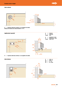
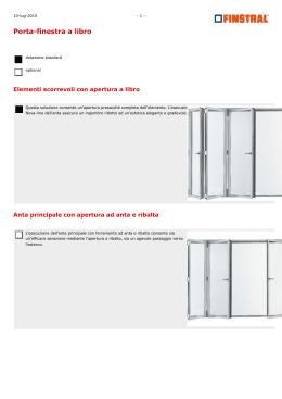
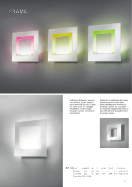
Art. ECA8
CENTRALINA DI COMANDO PER ANTE BATTENTI UNIVERSALE 230V
UNIVERSAL 230V CONTROL UNIT FOR SWING GATES
UNITÉ DE COMMANDE UNIVERSELLE POUR VANTAUX BATTANTS 230V
MANUALE D’INSTALLAZIONE E USO - CONTROL UNIT FOR SWING GATES - MANUEL D'INSTALLATION ET D'UTILISATION
Il prodotto è conforme alla direttive europee 89/336/CEE, 92/31/CEE, 93/68/CEE, 73/23/CEE, 98/37/CEE, R&TTE 99/05/CE, 89/106/CE.
The product is conform to the european directives 89/336/CEE, 92/31/CEE, 93/68/CEE, 73/23/CEE, 98/37/CEE, R&TTE 99/05/CE, 89/106/CE,
Le produit est conforme à la norme européenne 89/336/CEE, 92/31/CEE, 93/68/CEE, 73/23/CEE, 98/37/CEE, R&TTE 99/05/CE, 89/106/CE,.
I
Cod. S6I.ECA.800
GB
RL.02
F
2/2012
Le seguenti informazioni di sicurezza sono parti integranti ed essenziali del prodotto e devono essere
consegnate all'utilizzatore. Leggerle attentamente
in quanto forniscono importanti indicazioni riguardanti l'installazione, l'uso e la manutenzione.
E' necessario conservare il presente modulo e trasmetterlo ad eventuali subentranti nell'uso dell'impianto. L'errata installazione o l'utilizzo improprio del
prodotto può essere fonte di grave pericolo.
IMPORTANTE - INFORMAZIONI DI SICUREZZA
• L'installazione deve essere eseguita da personale professionalmente competente e in osservanza della legislazione nazionale ed europea
vigente.
• Dopo aver tolto l'imballo assicurarsi dell'integrità
dell'apparecchio, in caso di dubbio rivolgersi a
personale qualificato.
• I materiali d'imballaggio (cartone, sacchetti di
plastica, graffe, polistirolo ecc.) devono essere
smaltiti negli appositi contenitori e non devono
essere dispersi nell'ambiente soprattutto non
devono essere lasciati alla portata dei bambini.
• La posa in opera, i collegamenti elettrici e le regolazioni devono essere effettuati a "Regola
d'arte", assicurarsi che i dati di targa siano rispondenti a quelli della rete elettrica e accertare
che la sezione dei cavi di collegamento sia idonea ai carichi applicati, in caso di dubbio rivolgersi a personale qualificato.
- Gli elementi costruttivi meccanici devono essere
in accordo con quanto stabilito dalle Norme
EN12604 e EN12605.
- L’installazione deve essere effettuata nell’osservanza delle Norme EN12453 e EN 12445.
- I dispositivi di sicurezza, Norma EN 12978, permettono di proteggere eventuali aree di pericolo
da Rischi meccanici di movimento
N.B. L’interruttore che aziona l’apparecchio
deve essere installato in vista ad un’altezza non
superiore a 1,5m e lontano da pezzi in movimento.
• Non installare il prodotto in ambienti a pericolo
di esplosione o disturbati da campi elettromagnetici. La presenza di gas o fumi infiammabili
costituisce un grave pericolo per la sicurezza.
• Assicurarsi che sia presente e/o prevedere a
monte dell’apparecchio un dispositivo di sezionamento con una distanza di apertura tra i contatti di almeno 3mm.
• Indicare chiaramente sul cancello, porta, serranda o barriera che sono comandati a distanza
mediante apposito cartello.
• La ELVOX s.p.a. non può essere considerata responsabile per eventuali danni causati qualora
vengano installati dei dispositivi e/o componenti
incompatibili ai fini dell'integrità del prodotto,
della sicurezza e del funzionamento.
• L'apparecchio dovrà essere destinato al solo
uso per il quale è stato concepito, ogni altra applicazione è da considerarsi impropria e quindi
pericolosa.
• Prima d'effettuare una qualsiasi operazione di
pulizia o di manutenzione, disinserire
l'apparecchio dalla rete, staccando la spina, o
spegnendo l'interruttore dell'impianto. Per la riparazione o sostituzione delle parti danneggiate,
dovranno essere utilizzati esclusivamente ricambi originali.
• L'installatore deve fornire tutte le informazioni
relative al funzionamento, alla manutenzione e
dell'utilizzo delle singole parti componenti e del
sistema nella sua globalità.
- Tutto quello che non è previsto espressamente
in queste istruzioni non è permesso.
The following safety information is an integral and
essential part of the product and must be delivered
to the user. Read it thoroughly as it provides important information regarding installation, use and
maintenance. Store this document carefully and
transfer it to any subsequent users of the system.
Incorrect installation or improper use of the product
may constitute a serious hazard.
IMPORTANT - SAFETY INFORMATION
• Installation must be performed by professionally qualified personnel in observance of current national and European legislation.
• After removing the packaging check the condition of the equipment. If in doubt, consult a
qualified technician.
• Packaging materials (carton, plastic bags, staples, polystyrene, etc.) must be disposed of in
suitable containers and must not be dispersed
into the environment. Above all they must be
kept out of the reach of children.
• The installation, electrical connections and settings must be executed in accordance with
sound engineering practice. Make certain that
the data on the data plate conforms to the
mains electrical supply data and make certain
that the section of the connection cables is
suitable for the loads applied.
- The mechanical construction elements must
meet the provisions of standards EN 12604 and
EN 12605.
- Installation must be carried out in accordance
with standards EN 12453 and EN 12445.
- Safety devices, standard EN 12978, protect any
danger areas against mechanical movement
risks.
NOTE: The switch for operating the unit must
be installed in a visible position at a height of
not more than 1.5m and away from moving
parts.
• Do not install the product in environments
where there is a risk of explosion or which are
disturbed by electromagnetic fields. The presence of inflammable gases or fumes constitutes
a serious hazard.
• Make certain that a disconnection device is fitted upstream of the unit with an opening gap
between the contacts of at least 3mm.
• Clearly indicate the use of a remote control on
the door, shutter or barrier by means of a specific notice.
• ELVOX s.p.a. denies all liability for damage incurred when devices and/or components are
used that are incompatible in terms of product
integrity, safety and operation.
• This equipment must be used exclusively as
specified in design; any other use is to be considered improper and therefore hazardous.
• Always disconnect the equipment from the
power supply by means of the main switch or
by removing the plug before performing maintenance or cleaning. Use exclusively original
spare parts for repairs and replacements.
• The installer must provide all information regarding operation, maintenance and use of the
single parts and the system as a whole.
- Anything not expressly specified in these instructions is not permitted.
2/36
Les consignes de sécurité suivantes font partie intégrante et fondamentale du produit et doivent être
conservées par l'utilisateur. Les lire attentivement,
car elles fournissent d'importantes indications concernant l'installation, l'emploi et l'entretien. Il est
nécessaire de conserver la présente notice et celles qui seront éventuellement transmises par la
suite. L'installation erronée ou l'emploi impropre de
l'appareil peuvent être une source de danger grave.
IMPORTANT - INFORMATIONS EN MATIÈRE DE
SÉCURITÉ
• L'installation doit être réalisée par du personnel
professionnellement compétent et conformément à la réglementation nationale et européenne en vigueur.
• Après avoir enlevé l'emballage, s'assurer que
l'appareil est en bon état ; dans le doute,
s'adresser à du personnel qualifié.
. Les matériaux d'emballage (carton, sachets en
plastique, agrafes, polystyrène etc.) doivent être
jetés dans des conteneurs spéciaux et non pas
dans l'environnement ; ils ne doivent pas être
laissés à la portée des enfants.
La pose, les connexions électriques et les réglages doivent être effectués « dans les règles
de l'art » ; s'assurer que les spécifications sur la
plaque signalétique sont conformes à celles du
réseau électrique et que la section des câbles
de connexion est adaptée aux charges appliquées ; dans le doute, s'adresser à du personnel qualifié.
- Les organes mécaniques doivent être
conformes aux dispositions des Normes
EN12604 et EN12605.
- L’installation doit être effectuée conformément
aux Normes EN12453 et EN 12445.
- Les dispositifs de sécurité, Norme EN 12978,
permettent de protéger les éventuelles zones
dangereuses contre les Risques de mouvement
mécanique
N.B. L’interrupteur qui actionne l'appareil doit
être installé de façon visible, à une hauteur inférieure à 1,5 m et à l'écart d'organes en mouvement.
Ne pas installer l'appareil dans des endroits présentant des risques d'explosion ou perturbés
par des champs électromagnétiques. La présence de gaz ou de fumées inflammables menace gravement la sécurité.
S'assurer qu'un disjoncteur se trouve et/ou soit
prévu en amont de l’appareil avec une distance
d'ouverture entre les contacts d'au moins 3 mm.
• Signaler clairement sur le portail avec un panneau la présence du vantail, du rideau ou de la
barrière commandés à distance.
• ELVOX s.p.a. ne peut être tenue responsable
des éventuels dommages provoqués lorsque
des dispositifs et/ou des composants incompatibles sont installés et ce, afin de préserver l'état,
la sécurité et le fonctionnement de l'appareil.
• L'appareil ne devra être destiné qu'à l'usage
pour lequel il a été conçu ; toute autre application est considérée comme impropre et donc
dangereuse.
• Avant d'effectuer une opération quelconque de
nettoyage ou d'entretien, débrancher l'appareil
du réseau, en détachant la fiche ou en éteignant
l'interrupteur de l'installation. Pour la réparation
ou le remplacement des pièces endommagées,
utiliser exclusivement des pièces détachées
d'origine.
• L'installateur doit fournir toutes les informations
relatives au fonctionnement, à l'entretien et à
l'emploi des différentes parties et du système en
général.
- Tout ce qui n'est pas expressément prévu dans
ces instructions est interdit.
FASE
Motore 1
Motor 1
Moteur 1
3/36
Alimentazione rete
M1 - 2° anta in apertura
FOTOCELLULA 1 N.C.
FOTOCELLULA 2 E BORDO N.C.
Motore 2
Motor 2
Moteur 2
STOP N.C.
COMUNE
START PED.
APRE/CHIUDE N.O.
+ LAMPEGGIANTE A LED
- LAMPEGGIANTE A LED
-24 ACCESSORI
+24 ACCESSORI
-AUX
ELETTROSERRATURA
ELETTROSERRATURA
-2CAN
CHIUDI
APRI
COM
CHIUDI
APRI
COM
LAMPEGGIANTE
LAMPEGGIANTE
NEUTRO
TERRA
I
COLLEGAMENTI EC80
Art. ELA2
Art. ELA3
M1 - 1° anta in apertura o monoanta
I
CARATTERISTICHE GENERALI
L’apparecchiatura EC80 è stata progettata per controllare il funzionamento di attuatori elettromeccanici a 230 V AC, per l’automazione di
cancelli ad ante battenti. Ogni altro uso è da considerarsi improprio e quindi pericoloso.
È vietato utilizzare il prodotto per scopi diversi da quelli previsti o impropri.
È vietato manomettere o modificare il prodotto.
Il costruttore non assume responsabilità per il mancato rispetto di tali prescrizioni.
Dati tecnici
Prima installare il prodotto, verificare che i limiti di temperatura indicati siano adeguati all’ambiente di installazione.
TENSIONE DI ALIMENTAZIONE MONOFASE
FREQUENZA
ALIMENTAZIONE MOTORE
POTENZA MASSIMA MOTORE
TENSIONE PER DISPOSITIVI ESTERNI
POTENZA MASSIMA ASSORBITA DISP. EST.
PROTEZIONE APPARECCHIATURA E ACCESSORI
PROTEZIONE MOTORE
CAMPO DI TEMPERATURE
GRADO DI PROTEZIONE
230 V AC +6% -10 %
50 Hz
230 V AC +6% -10 %
300 W
24 V DC +15% -10%
20 W
fusibile ritardato T1 A (F1)
fusibile da 5 A (F2)
- 20 ÷ +70 °C interno cassonetto
IP55
MISURE DI INGOMBRO ECA8 (mm)
INSTALLAZIONE MECCANICA
Per una corretta istallazione fissare il box in in un luogo sicuro e al riparo dagli agenti atmosferici. Per fissare il box nella parete bisogna
togliere le 4 viti in plastica, aprire il coperchio e fissare il box al muro con 4 tasselli.
N.B.: per determinare i punto di apertura e chiusura delle ante, se non usata la scheda fine corsa (opzionale) sono necessari dei fermi meccanici posti in apertura e chiusura desiderata (Art. ZD27).
4/36
CARATTERISTICHE GENERALI
I
INSTALLAZIONE ELETTRICA
L’apparecchiatura è installata nel box elettrico.
1 - Inserito l’attuatore eseguire i collegamenti seguendo le operazioni riportate nella centralina ECA8 (Fig. 1).
2 - Scegliere percorsi brevi per i collegamenti con cavo multipolare del tipo previsto dalle normative.
3 - L’impianto di messa a terra del cancello deve essere conforme alle norme vigenti.
La casa costruttrice declina ogni responsabilità per danni derivanti da eventuali negligenze in materia.
4 - In accordo con la normativa europea in materia di sicurezza si consiglia di inserire un interruttore bipolare di rete per poter togliere
l’alimentazione in caso di manutenzione del cancello e di scollegare il morsetto delle alimentazioni della scheda.
5 - Verificare che ogni singolo dispositivo (fotocellule, selettore a chiave, ecc.) sia efficiente ed efficace.
6 - Applicare adeguate misure integrative di sicurezza all’automazione se il caso lo richiede.
Montaggio/sostituzione della scheda
In caso di SOSTITUZIONE, occorre:
- IMPORTANTE! Interrompere l’alimentazione elettrica.
- Interrompere tutti i collegamenti.
- Rimuovere la scheda svitando le viti di fissaggio.
- Posizionare e fissare la nuova scheda.
- Ripristinare i collegamenti.
- Ripristinare l’alimentazione elettrica; riprogrammare e memorizzare i radiocomandi.
Collegamenti elettrici e allacciamento alla tensione di rete
I contatti N.C. devono essere ponticellati verso massa (morsetto GND) quando non vengono utilizzati. In caso contrario l’automazione NON
PUO’ funzionare!
Se un ingresso di tipo N.O. è chiuso, o un ingresso di tipo N.C. è aperto, il led PROG-DL8 lampeggia ad alta frequenza.
SCHEDE PLUGIN - CONFIGURAZIONE
EC 80 può funzionare da sola o con l'innesto di una scheda plugin (non fornita di serie).
Il connettore CN2 (SLOT 1) può ospitare la seguente scheda plugin:
- art. ECFC (Gestione finecorsa - opzionale)
COMUNE
FINECORSA APERTURA M2
FINECORSA APERTURA M2
COMUNE
FINECORSA APERTURA M1
FINECORSA APERTURA M1
Alla scheda ECFC vanno connessi i finecorsa di posizione aperto e chiuso delle ante.
Durante l'apprendimento viene anche rilevata e memorizzata la tipologia dei contatti dei finecorsa, se Normalmente Aperti (N.A.) oppure
Normalmente Chiusi ( N.C).
E' possibile utilizzare finecorsa di tipologia differente per le due ante.
MESSA IN FUNZIONE
Al momento della prima messa in funzione del sistema accertarsi che nessuno sia presente in prossimità del cancello automatico.
Dopo aver completato e verificato i collegamenti elettrici, dare tensione all’apparecchiatura ed effettuare immediatamente
l’APPRENDIMENTO (vedi paragrafo Programmazione)
5/36
I
PROGRAMMAZIONE
PROGRAMMAZIONE
Dopo un reset o dopo aver alimentato la scheda, il tempo di corsa della prima manovra di chiusura è aumentato di 50 sec circa,
per consentire il completamento del movimento in ogni caso.
Nelle configurazioni che prevedono la presenza dei finecorsa, durante l'apprendimento viene anche rilevata e memorizzata la tipologia dei contatti dei finecorsa (N.A. oppure N.C). E' possibile utilizzare finecorsa di tipologia differente per le due ante.
1.
Procedure di apprendimento ridotte
Le procedure ridotte permettono di apprendere solo gli spazi di rallentamento, mentre i ritardi d'anta vengono fissati a 2 sec in apertura e
4 sec in chiusura
CON RALLENTAMENTO
-
Chiudere completamente il cancello.
Premere il pulsante di apprendimento P1 per almeno 3 secondi
Il led PROG-DL8 comincia a lampeggiare
Rilasciare il pulsante P1
Premere START, pulsante P3 (AP/CH):
• La prima anta si muove in apertura con velocità normale
Quando si decide di cominciare la fase di corsa rallentata premere START.
Inizia la fase di corsa rallentata
Senza scheda FC: Quando l’anta arriva alla totale apertura premere START
Con scheda FC:
Attendere che l'anta arrivi alla totale apertura.
• La seconda anta si muove in apertura con velocità normale
Quando si decide di cominciare la fase di corsa rallentata premere START.
Inizia la fase di corsa rallentata
Senza scheda FC: Quando l’anta arriva alla totale apertura premere START
Con scheda FC:
Attendere che l'anta arrivi alla totale apertura
• La seconda anta si muove in chiusura con velocità normale
Quando si decide di cominciare la fase di corsa rallentata premere START
Inizia la fase di corsa rallentata
Senza scheda FC: Quando l’anta arriva alla totale chiusura premere START
Con scheda FC:
Attendere che l'anta arrivi alla totale chiusura
• La prima anta si muove in chiusura con velocità normale
Quando si decide di cominciare la fase di corsa rallentata premere START
Inizia la fase di corsa rallentata
Senza scheda FC: Quando l’anta arriva alla totale chiusura premere START
Con scheda FC:
Attendere che l'anta arrivi alla totale chiusura
-
Attendere che il led PROG-DL8 si spenga.
Apprendimento terminato.
SENZA RALLENTAMENTO
-
Regolare al massimo il trimmer TR4 (VRALL)
Chiudere completamente il cancello
Premere il pulsante di apprendimento P1 per almeno 3 secondi
Il led PROG-DL8 comincia a lampeggiare
Rilasciare il pulsante P1
Premere START, pulsante P3 (AP/CH):
• La prima anta si muove in apertura con velocità normale
Senza scheda FC:
Con scheda FC:
Quando l’anta arriva alla totale apertura premere START
Attendere che l'anta arrivi alla totale apertura
• La seconda anta si muove in apertura con velocità normale
Senza scheda FC:
Con scheda FC:
Quando l’anta arriva alla totale apertura premere START
Attendere che l'anta arrivi alla totale apertura
• La seconda anta si muove in chiusura con velocità normale
6/36
PROGRAMMAZIONE
I
Senza scheda FC: Quando l’anta arriva alla totale chiusura premere START
Con scheda FC: Attendere che l'anta arrivi alla totale chiusura
•
La prima anta si muove in chiusura con velocità normale
Senza scheda FC: Quando l’anta arriva alla totale chiusura premere START
Con scheda FC: Attendere che l'anta arrivi alla totale chiusura
-
Attendere che il led PROG-DL8 si spenga.
Apprendimento terminato.
2.
Procedure di apprendimento complete
Le procedure complete permettono di apprendere anche i ritardi d'anta
CON RALLENTAMENTO
-
Chiudere completamente il cancello.
Premere il pulsante di apprendimento P1 per almeno 3 secondi
Il led PROG-DL8 comincia a lampeggiare
Non rilasciare il pulsante P1 e mantenerlo premuto per altri 3 secondi
Il led PROG-DL8 comincia a lampeggiare a frequenza più elevata
Rilasciare il pulsante P1
Premere START, pulsante P3 (AP/CH):
• La prima anta si muove in apertura con velocità normale
Quando si decide di cominciare la fase di corsa rallentata premere START
Inizia la fase di corsa rallentata
Senza scheda FC
Con scheda FC:
Quando l’anta arriva alla totale apertura premere START
Attendere che l'anta arrivi alla totale apertura
• La seconda anta si muove in apertura con velocità normale
Quando si decide di cominciare la fase di corsa rallentata premere START
Inizia la fase di corsa rallentata
Senza scheda FC:
Con scheda FC:
Quando l’anta arriva alla totale apertura premere START
Attendere che l'anta arrivi alla totale apertura
• La seconda anta si muove in chiusura con velocità normale
Quando si decide di cominciare la fase di corsa rallentata premere START
Inizia la fase di corsa rallentata
Senza scheda FC:
Con scheda FC:
Quando l’anta arriva alla totale chiusura premere START
Attendere che l'anta arrivi alla totale chiusura
• La prima anta si muove in chiusura con velocità normale
Quando si decide di cominciare la fase di corsa rallentata premere START
Inizia la fase di corsa rallentata
Senza scheda FC:
Con scheda FC:
Quando l’anta arriva alla totale chiusura premere START
Attendere che l'anta arrivi alla totale chiusura
• Premere START: si muove la prima anta in apertura e appena si decide che il tempo di sfasamento dell’anta è sufficiente premere nuovamente START: si muove la seconda anta
• Premere START: si muove la seconda anta in chiusura e appena si decide che il tempo di sfasamento dell’anta è sufficiente premere
nuovamente START: si muove la prima anta
-
Attendere che il led PROG-DL8 si spenga
Apprendimento terminato.
7/36
I
PROGRAMMAZIONE
SENZA RALLENTAMENTO
-
Regolare al massimo il trimmer TR4 (V.RALL)
Chiudere completamente il cancello.
Premere il pulsante di apprendimento P1 per almeno 3 secondi
Il led PROG-DL8 comincia a lampeggiare
Non rilasciare il pulsante P1 e mantenerlo premuto per altri 3 secondi
Il led PROG-DL8 comincia a lampeggiare a frequenza più elevata
Rilasciare il pulsante P1
Premere START, pulsante P3 (AP/CH):
• La prima anta si muove in apertura con velocità normale
Senza scheda FC:
Con scheda FC:
Quando l’anta arriva alla totale apertura premere START
Attendere che l'anta arrivi alla totale apertura
• La seconda anta si muove in apertura con velocità normale
Senza scheda FC:
Con scheda FC:
Quando l’anta arriva alla totale apertura premere START
Attendere che l'anta arrivi alla totale apertura
• La seconda anta si muove in chiusura con velocità normale
Senza scheda FC:
Con scheda FC:
Quando l’anta arriva alla totale chiusura premere START
Attendere che l'anta arrivi alla totale chiusura
• La prima anta si muove in chiusura con velocità normale
Senza scheda FC:
Con scheda FC:
Quando l’anta arriva alla totale chiusura premere START
Attendere che l'anta arrivi alla totale chiusura
• Premere START: si muove la prima anta in apertura e appena si decide che il tempo di sfasamento dell’anta è sufficiente premere nuovamente START: si muove la seconda anta
• Premere START: si muove la seconda anta in chiusura e appena si decide che il tempo di sfasamento dell’anta è sufficiente premere
nuovamente START: si muove la prima anta
-
Attendere che il led PROG-DL8 si spenga.
Apprendimento terminato.
3. Procedure di apprendimento monoanta
Le procedure monoanta permettono di configurare il cancello ad anta singola
CON RALLENTAMENTO
-
Chiudere completamente il cancello.
Premere il pulsante di apprendimento P1 per almeno 3 secondi
Il led PROG-DL8 comincia a lampeggiare
Non rilasciare il pulsante P1 e mantenerlo premuto per altri 3 secondi
Il led PROG-DL8 comincia a lampeggiare a frequenza più elevata
Non rilasciare il pulsante P1 e mantenerlo premuto per altri 3 secondi
Il led PROG-DL8 comincia a lampeggiare a frequenza più elevata
Rilasciare il pulsante P1
Premere START, pulsante P3 (AP/CH):
• La prima anta si muove in apertura con velocità normale
Quando si decide di cominciare la fase di corsa rallentata premere START
Inizia la fase di corsa rallentata
Senza scheda FC:
Quando l’anta arriva alla totale apertura premere START
Con scheda FC:
Attendere che l'anta arrivi alla totale apertura
• La prima anta si muove in chiusura con velocità normale
Quando si decide di cominciare la fase di corsa rallentata premere START
Inizia la fase di corsa rallentata
Senza scheda FC:
Quando l’anta arriva alla totale chiusura premere START
Con scheda FC:
Attendere che l'anta arrivi alla totale chiusura
-
Attendere che il led PROG-DL8 si spenga.
Apprendimento terminato.
8/36
PROGRAMMAZIONE
I
SENZA RALLENTAMENTO
•
•
•
•
•
•
•
•
•
•
Regolare al massimo il trimmer TR4 (VRALL)
Chiudere completamente il cancello.
Premere il pulsante di apprendimento P1 per almeno 3 secondi
Il led PROG-DL8 comincia a lampeggiare
Non rilasciare il pulsante P1 e mantenerlo premuto per altri 3 secondi
Il led PROG-DL8 comincia a lampeggiare a frequenza più elevata
Non rilasciare il pulsante P1 e mantenerlo premuto per altri 3 secondi
Il led PROG-DL8 comincia a lampeggiare a frequenza più elevata
Premere START: La prima anta si muove in apertura con velocità normale
Premere START, pulsante P3 (AP/CH):
• La prima anta si muove in apertura con velocità normale
Senza scheda FC:
Quando l’anta arriva alla totale apertura premere START
Con scheda FC:
Attendere che l'anta arrivi alla totale apertura
• La prima anta si muove in chiusura con velocità normale
Senza scheda FC:
Quando l’anta arriva alla totale chiusura premere START
Con scheda FC:
Attendere che l'anta arrivi alla totale chiusura
-
Attendere che il led PROG-DL8 si spenga.
Apprendimento terminato.
LOGICHE DI FUNZIONAMENTO
Selezionare una logica di funzionamento tramite i dip switch DSW1 5, 6 e 7 facendo riferimento alla tabella sottostante (dopo ogni cambiamento di posizione di questi dip switch è necessario ponticellare per qualche secondo i contatti JR1 RESET perché il cambiamento abbia
effetto):
dip 5
OFF
OFF
OFF
OFF
ON
ON
ON
ON
dip 6
OFF
OFF
ON
ON
ON
ON
OFF
OFF
dip 7
OFF
ON
OFF
ON
OFF
ON
OFF
ON
DSW1 - Logica di funzionamento
Logica
Automatica condominiale
Automatica condominiale + cortesia (*)
Super automatica
Super automatica + cortesia (*)
Automatica
Automatica + cortesia (*)
Semi automatica
Passo - Passo
(*) La funzione cortesia abilita la chiusura dopo 5 secondi che le fotocellule hanno ricevuto un impulso indipendentemente dal tempo di
sosta impostato.
AUTOMATICA CONDOMINIALE:
un impulso di START a cancello chiuso comanda l'apertura. Un impulso di START in fase di apertura è ignorato. Una volta aperto, il cancello rimane in pausa per il tempo di sosta. Un impulso di START durante la pausa fa ripartire da zero il conteggio del tempo. Un impulso
di START in fase di chiusura comanda la riapertura.
SUPER AUTOMATICA:
un impulso di START a cancello chiuso comanda l'apertura. Un impulso di START in fase di apertura ferma il cancello, e in questo caso
un successivo impulso di START comanda la richiusura. Una volta aperto, il cancello rimane in pausa per il tempo di sosta. Un impulso di
START durante la pausa comanda la chiusura. Un impulso di START in fase di chiusura comanda la riapertura.
AUTOMATICA:
un impulso di START a cancello chiuso comanda l'apertura. Un impulso di START in fase di apertura è ignorato. Una volta aperto, il cancello rimane in pausa per il tempo di sosta. Un impulso di START durante la pausa comanda la chiusura. Un impulso di START in fase di
chiusura comanda la riapertura.
SEMI AUTOMATICA:
un impulso di START a cancello chiuso comanda l'apertura. Un impulso di START in fase di apertura ferma il cancello, e in questo caso
un successivo impulso di START comanda la richiusura. Il cancello rimane aperto fino ad un impulso di START che comanda la chiusura.
Un impulso di START in fase di chiusura comanda la riapertura.
PASSO – PASSO:
un impulso di START a cancello chiuso comanda l'apertura. Un impulso di START in fase di apertura ferma il cancello, e in questo caso
un successivo impulso di START comanda la richiusura. Il cancello rimane aperto fino ad un impulso di START che comanda la chiusura.
In fase di chiusura un impulso di START arresta il cancello e un altro impulso provoca la riapertura.
9/36
I
PROGRAMMAZIONE
INGRESSI, USCITE E FUNZIONAMENTI
Ingressi
Descrizione
N. 20 COM
Comune per i comandi
N. 21 AP/CH
Comanda l’apertura/chiusura del’anta. Vedi logiche di funzionamento.
N. 24 STOP
Comanda l’arresto di ogni movimento e finché è attivo impedisce ogni movimento. Contatto NC.
N. 22 APED
Comanda l’apertura pedonale se il cancello è chiuso.
Comanda la chiusura se il cancello è aperto o fermo.
N.23 COM
Comune per le sicurezze
Fotocellula, contatto NC, se in chiusura, inverte il movimento e finché è impegnata impedisce la chiusura.
Fotocellula in apertura, comanda l’arresto di ogni movimento e finché è impegnata impedisce ogni
movimento. Al disimpegno: apertura.
N. 25 FOTO
N. 26 STPA
Uscite
Descrizione
N. 12 (-)
N. 13 (+)
2CAN
Uscita secondo canale, se dip 3 = OFF si attiva alla ricezione del radiocomando.
Se dip 3 = ON collegare il tx fotocellule per il test
N. 13 (+)
N. 14 (-)
SERR
Uscita alimentazione serrattura
N. 15 (-)
N. 13 (+)
N. 16 (+)
N. 17 (-)
AUX
Uscita tensione 24Vcc per la segnalazione remota dello stato dell’automazione:
(luce spia) • accesa in chiusura
• accesa in apertura
• luce fissa : battenti NON chiusi
Accessori Uscita 24Vcc. Alimentazione fotocellule
± 24V
N. 18 (-)
N. 19 (+)
LAMP
± 24V
Uscita intermittente per lampeggiante a LED.
Funzionamenti
Descrizione
OSTACOLO IN CHIUSURA
(solo config. 3, 4, 5 e 6)
In caso di un ostacolo in chiusura: il cancello inverte immediatamente il movimento ed esegue fino a 3
tentativi di chiusura. Se l’ostacolo permane, il cancello resta fermo in attesa di un comando.
OSTACOLO IN APERTURA In caso di un ostacolo in apertura: il cancello inverte immediatamente il movimento per 1,5 sec. e si
(solo config. 3, 4, 5 e 6)
arresta.
COLPO DI SGANCIO
L’azionamento in apertura viene preceduto da un breve azionamento in senso inverso al fine di togliere il carico sulle ante e agevolare lo sblocco dell’elettroserratura.
COLPO DI AGGANCIO
L’azionamento in chiusura viene seguito da un breve azionamento a potenza piena al fine di agevolare
il blocco dell’elettroserratura.
DIP SWITCH
DSW1
Funzione
ON
OFF
dip 1
Colpo aggancio / sgancio
Abilitato
Disabilitato
dip 2
Prelampeggio
Abilitato
Disabilitato
dip 3
Out 2CAN
Alim. TX Fotocellule (test)
Secondo canale radiocomando
dip 4
In STPA
Bordo Resistivo
Fotocellula 2
dip 8
Test fotocellule
Abilitato
Disabilitato
DSW2
dip 1
dip 2
Funzione
Non Usato
Spunto in partenza
ON
Disabilitato
10/36
OFF
Abilitato
I
PROGRAMMAZIONE
TRIMMER
TR1-PAUSA: regola il tempo di sosta (tempo per cui il cancello resta fermo prima della chiusura automatica) che varia da 1 a 120 secondi.
TR2-FORZA/M1 TR3-FORZA/M2: regolano la coppia dei motori. Per motori con frizione o oleodinamici bisogna ruotare i trimmer al massimo (completa rotazione in senso orario).
TR4-VRALL regola la velocità in fase di rallentamento che potrà essere regolata entro i parametri di sicurezza. Regolando il trimmer al massimo (completa rotazione in senso orario) viene escluso il rallentamento (vedi procedura apprendimento senza rallentamento).
Trimmer
Funzione
Tempo sosta
Range
Da 1 a 120 sec
TR2-FORZA/M1
Forza motore 1
Da 20 a 100%
MAX: oleodinamici
TR3-FORZA/M2
Forza motore 2
Da 20 a 100%
MAX: oleodinamici
TR4-VRALL
Vel. rallentam.
Da 0 a 100%
MAX: rall. escluso
TR1-PAUSA
Funzioni speciali
-
APPRENDIMENTO RADIOCOMANDI
L'apparecchiatura EC 80 è dotata di un decodificatore incorporato capace di memorizzare fino a 128 telecomandi di tipo rolling code oppure 128 telecomandi del tipo codice fisso.
Il primo telecomando appreso da un apparecchiatura nuova o dopo una cancellazione totale dei telecomandi appresi fissa il tipo di telecomando (rolling code o codice fisso)
Memorizzazione codice radio (Funzione START)
In posizione di cancello chiuso, premere il pulsante P2 e tenerlo premuto fino a quando il led PROG-DL8 comincia a lampeggiare. Rilasciare il pulsante P2. Entro 10 secondi attivare il tasto del radiocomando da apprendere che si desidera sia associato al comando di START.
L'avvenuto apprendimento sarà segnalato da un lampeggio contemporaneo del led PROG-DL8, del lampeggiante e della lampada spia,
seguito dalla cessazione del lampeggio del led PROG-DL8.
Memorizzazione codice radio secondo canale (Funzione Out 2CAN o apertura Pedonale).
Ripetere l'operazione per ogni radiocomando da apprendere.
In posizione di cancello chiuso, premere il pulsante P2 e tenerlo premuto fino a quando il led PROG-DL8 comincia a lampeggiare; non rilasciare il pulsante e attendere che il lampeggio diventi più veloce. Rilasciare il pulsante P2.
Entro 10 secondi attivare il tasto del telecomando da apprendere che si desidera sia associato all'uscita 2CAN (se dip3 = OFF) o al comando apertura pedonale (se dip 3 = ON). L'avvenuto apprendimento sarà segnalato da un lampeggio contemporaneo del led PROG-DL8,
del lampeggiante e della lampada spia, seguito dalla cessazione del lampeggio del led PROG-DL8.
Ripetere l'operazione per ogni radiocomando da apprendere.
Cancellazione totale dei radiocomandi appresi
In posizione di cancello chiuso, premere il pulsante P2 e tenerlo premuto fino a quando il led PROG-DL8 comincia a lampeggiare; non rilasciare il pulsante e attendere che il lampeggio diventi più veloce; non rilasciare il pulsante e attendere che il lampeggio diventi velocissimo; non rilasciare il pulsante. L'avvenuta cancellazione di TUTTI i radiocomandi appresi sarà segnalata da un lampeggio contemporaneo
del led PROG-DL8, del lampeggiante e della lampada spia, seguito dalla cessazione del lampeggio del led PROG-DL8.
TEST FOTOCELLULE
Per abilitare la funzione di test delle fotocellule, alimentarne il trasmettitore attraverso l'uscita 2CAN (vedi schema) , posizionare il dip 3 in
ON e il dip 8 in ON. In tal modo, al termine di ogni manovra di apertura verrà effettuato il test delle fotocellule. Nel caso il test non andasse
a buon fine, la successiva manovra di chiusura NON verrà effettuata e verranno emessi due lampeggi di avvertimento tramite il led PROGDL8 e l'uscita AUX.
11/36
I
PROGRAMMAZIONE
MANUTENZIONE
• Per garantire l'efficienza del prodotto è indispensabile che personale professionalmente competente effettui la manutenzione nei tempi
prestabiliti dall'installatore, dal produttore e della legislazione vigente.
• Gli interventi di installazione, manutenzione, riparazione e pulizia devono essere documentati. Tale documentazione deve essere conservata dall'utilizzatore, a disposizione del personale competente preposto.
• Prima di effettuare una qualsiasi operazione di pulizia o di manutenzione disinserire l'apparecchiatura dalla rete staccando la spina, o spegnendo l'interruttore dell'impianto.
• Nel caso chel'alimentazione dovesse essere presente per verifiche di funzionamento, si raccomanda di controllare o disabilitare ogni dispositivo di comando (radiocomandi, pulsantiere ecc.) ad eccezione del dispositivo usato dall'addetto alla manutenzione.
N.B.: Si ricorda che in base alla D.M. 2006/42 CEE, alla conclusione dell’installazione occorre compilare una Dichiarazione di Conformità
della macchina e una Proposta di Manutenzione Programmata e rilasciare tali documenti all’utente.
MANUTENZIONE PROGRAMMATA
La manutenzione consigliata per l’impianto elettrico è la seguente:
Operazione
Periodicità
media
Verifica del buon funzionamento dei dispositivi di rilevamento e antischiacciamento (fotocellule, detector, sicurezza coste)
6 mesi
e delle regolazioni.
Controllo del buon funzionamento dell’impianto elettrico e test di intervento per dispersione dell’interruttore automatico
differenziale posto a protezione dell’impianto.
Controllare l’interno del box elettrico, che deve essere mantenuto pulito e preservato da insetti o umidità.
Verificare l’efficienza delle batterie dei telecomandi ed eventualmente sostituirle.
6 mesi
6 mesi
6 mesi
Eliminare eventuali ostacoli interposti che oscurino permanentemente il raggio delle fotocellule (es: rami o cespugli).
6 mesi
AVVERTENZE PER L'UTILIZZATORE
- Leggere attentamente l'istruzioni e la documentazione allegata.
- Il prodotto dovrà essere destinato all'uso per il quale è stato espressamente concepito, ogni altro utilizzo è da considerarsi improprio e
quindi pericoloso.
- L'informazioni contenute nel presente documento e nella documentazione allegata, possono essere oggetto di modifiche senza alcun
preavviso. Sono infatti fornite a titolo indicativo per l'applicazione del prodotto.
- In caso di guasto e/o cattivo funzionamento dell'automazione, disinserire l'apparecchio dalla rete spegnendo l'interruttore dell'impianto
e rivolgersi solo a personale professionalmente qualificato oppure al centro di assistenza autorizzato. Evitare qualsiasi tentativo di riparazione e d'intervento diretto.
- Si raccomanda di far effettuare un controllo annuale del funzionamento generale dell'automazione e dei dispositivi di sicurezza da personale qualificato.
Le istruzioni fornite sono parte integrale ed essenziale del prodotto e devono essere lette attentamente, poiché contengono importanti avvertimenti per l’uso e la manutenzione. Queste istruzioni devono essere conservate e consegnate a tutti i futuri possibili utilizzatori.
L’apparecchiatura EC80 è stata progettata per controllare il funzionamento di attuatori elettromeccanici a 230 V AC per l’automazione di
cancelli ad ante battenti.
È vietato utilizzare il prodotto per scopi diversi da quelli previsti o impropri. Ogni altro utilizzo è improprio e quindi pericoloso. È vietato manomettere o modificare il prodotto.
Si raccomanda di consultare la Ditta Installatrice dell’automazione e stabilire un piano di manutenzione programmata, come richiesto dalle
normative di settore (per i Paesi CEE: Direttiva Macchine 2006/42/CEE). Far eseguire periodicamente una corretta manutenzione, in base
al libretto di manutenzione rilasciato dall’installatore.
Il collegamento, il collaudo e la messa in funzione, così come le verifiche periodiche e gli interventi di manutenzione, inclusa la pulizia dell’azionamento, possono essere eseguiti soltanto da tecnici specializzati e formati sul prodotto.
All’utilizzatore non è consentito intervenire sull’impianto e sull’apparec-chiatura di controllo, né operare all’interno del box elettrico. In caso
di guasti o di mancanza di energia elettrica si può manovrare il CANCELLO manualmente (vedi manuale di installazione dell’attuatore).
AVVERTENZE DI SICUREZZA
1. Non entrare nel raggio d'azione della automazione mentre essi è in movimento, attendere fino alla completa conclusione della manovra.
2. Azionare l'automazione solo quando essa è completamente visibile e priva di qualsiasi impedimento.
3. Non permettere a bambini o ad animali di giocare o sostare in prossimità del raggio d'azione. Non permettere ai bambini di giocare con
i comandi di apertura o con il radiocomando.
4. Non opporsi al moto dell'automazione poiché può causare situazione di pericolo.
5. Non toccare l'apparecchio con mani bagnate e/o piedi bagnati.
12/36
Motor 1
Mains power supply
13/36
M1 - Leaf 2 opening
Motor 2
Art. ELA2
Flashing light 12V 5W
Art. ELA3
M1 - Leaf 1 opening or single-leaf
PHOTOCELL 2 AND EDGE N.C.
PHOTOCELL 1 N.C.
STOP N.C.
COMMON
START PED.
OPEN/CLOSE N.O.
+ LED FLASHING LIGHT
- LED FLASHING LIGHT
-24 ACCESSORIES
+24 ACCESSORIES
-AUX
ELECTRIC LOCK
ELECTRIC LOCK
-2CAN
CLOSE
OPEN
COM
CLOSE
OPEN
COM
FLASHING LIGHT
FLASHING LIGHT
NEUTRAL
EARTH
PHASE
EC80
GB
EC80 CONNECTIONS
GB
GENERAL FEATURES
The EC80 equipment has been designed to control the operation of 230 V AC electromechanical actuators for the automation of swing gates.
Any other use is to be considered improper and therefore hazardous.
It is prohibited to use the product for an improper purpose or for any purpose other than its intended use.
It is prohibited to tamper with or modify the product.
The manufacturer assumes no liability for failure to comply with these requirements.
Technical data
Before installing the product, check that the temperature limits indicated are suitable for the installation environment.
SINGLE-PHASE SUPPLY VOLTAGE
230 V AC +6% -10 %
FREQUENCY
50 Hz
MOTOR SUPPLY VOLTAGE
230 V AC +6% -10 %
MOTOR MAXIMUM POWER
300 W
VOLTAGE FOR EXTERNAL DEVICES
24 V DC +15% -10%
MAXIMUM ABSORBED POWER EXT. DEV.
20 W
EQUIPMENT AND ACCESSORIES PROTECTION
T1 A time-delay fuse (F1)
MOTOR PROTECTION
5 A fuse (F2)
TEMPERATURE RANGE
- 20 to +70 °C inside enclosure
PROTECTION RATING
IP55
ECA8 OVERALL DIMENSIONS (mm)
MECHANICAL INSTALLATION
For correct installation, fix the box in a secure place where it is protected from the weather. To mount the box on the wall remove the 4
plastic screws, open the cover and fasten the box to the wall with 4 plugs.
NOTE: in order to determine the opening and closing points of the gate leaves, if the limit switch card (optional) is not used, mechanical
stops must be fitted at the desired opening and closing positions (Art. ZD27).
14/36
GENERAL FEATURES
GB
ELECTRICAL INSTALLATION
The equipment is installed in the electrical housing.
1 - After inserting the actuator, make the connections by following the operations indicated in the ECA8 control unit (Fig. 1).
2 - Select short routes for the connections with multicore cable of the type prescribed by current standards.
3 - The gate’s earthing device must conform to current standards.
The manufacturer accepts no liability for damage arising from negligence in this respect.
4 - In accordance with European safety standards, it is recommended that a mains two-pole switch is installed in order to be able to disconnect the power supply before carrying out maintenance on the gate and to disconnect the terminal of the card power supplies.
5 - Check that each individual device (photocells, key selector, etc.) works effectively and efficiently.
6 - Apply adequate supplementary safety measures to the automatic system where required.
Fitting/replacing the card
In case of REPLACEMENT, it is necessary to:
- IMPORTANT! Switch off the power supply.
- Disconnect all connections.
- Remove the card by undoing the fixing screws.
- Position the new card and fix in place.
- Restore the connections.
- Restore the power supply, reprogram and save the radio controls.
Electrical connections and hook-up to the mains supply
The N.C. contacts must be jumpered to earth (GND terminal) when not used. Otherwise the automatic gate system will NOT function!
If a N.O. input is closed, or a N.C. input is open, the PROG-DL8 LED flashes at high frequency.
PLUGIN CARDS - CONFIGURATION
EC 80 can operate on its own or with the insertion of a plugin card (purchased separately).
Connector CN2 (SLOT 1) can accommodate the following plugin card:
- art. ECFC (Limit switch control - optional)
COMMON
CLOSING LIMIT STOP M2
OPENING LIMIT STOP M2
COMMON
CLOSING LIMIT STOP M1
OPENING LIMIT STOP M1
The ECFC card must be connected to the open and closed position limit switches of the gate leaves.
During the travel path learning procedure, the type of the limit switch contacts is also memorised, which is either Normally Open (N.O.) or
Normally Closed (N.C.).
Limit switches of different type can be used for the two gate leaves.
START-UP
Before starting up the system for the first time, make sure that no-one is in the vicinity of the automatic gate.
After completing and checking the electrical connections, power up the equipment and immediately execute TRAVEL PATH LEARNING (see
Programming paragraph).
15/36
GB
PROGRAMMING
PROGRAMMING
After a reset or after powering up the card, the travel time of the first closing manoeuvre is increased by approximately 50
seconds, to enable the completion of the manoeuvre in all cases.
In configurations that require the presence of limit switches, during the travel path learning procedure the type of the limit switch
contacts is also detected and memorised (N.O. or N.C). Limit switches of different type can be used for the two gate leaves.
1.
Reduced learning procedures
The reduced learning procedures memorises only the slow-down spaces, whereas the leaf delays are fixed at 2 seconds on opening and
4 seconds on closing
WITH SLOW-DOWN
-
Close the gate completely
Press the P1 learning button for at least 3 seconds
The PROG-DL8 LED starts flashing
Release button P1
Press START, button P3 (AP/CH – open/close):
• The first leaf begins to open at standard speed
When you decide to start the slow-stroke phase, press START
The slow-stroke phase starts
Without LS card: When the leaf has opened completely, press START
With LS card:
Wait until the leaf opens completely.
• The second leaf begins to open at standard speed
When you decide to start the slow-stroke phase, press START
The slow-stroke phase starts
Without LS card: When the leaf has opened completely, press START
With LS card:
Wait until the leaf opens completely
• The second leaf begins to close at standard speed
When you decide to start the slow-stroke phase, press START
The slow-stroke phase starts
Without LS card: When the leaf has closed completely, press START
With LS card:
Wait until the leaf closes completely
• The first leaf begins to close at standard speed
When you decide to start the slow-stroke phase, press START
The slow-stroke phase starts
Without LS card: When the leaf has closed completely, press START
With LS card:
Wait until the leaf closes completely
- Wait until the PROG-DL8 LED turns off.
- Learning finished.
WITHOUT SLOW-DOWN
-
Regulator trimmer TR4 (SLOSP – slow-down speed) to the maximum setting
Close the gate completely
Press the P1 learning button for at least 3 seconds
The PROG-DL8 LED starts flashing
Release button P1
Press START, button P3 (AP/CH – open/close):
• The first leaf begins to open at standard speed
Without LS card: When the leaf has opened completely, press START
With LS card:
Wait until the leaf opens completely
• The second leaf begins to open at standard speed
Without LS card: When the leaf has opened completely, press START
With LS card:
Wait until the leaf opens completely
16/36
PROGRAMMING
GB
• The second leaf begins to close at standard speed
Without LS card: When the leaf has closed completely, press START
With LS card:
Wait until the leaf closes completely
• The first leaf begins to close at standard speed
Without LS card: When the leaf has closed completely, press START
With LS card:
Wait until the leaf closes completely
- Wait until the PROG-DL8 LED turns off.
- Learning finished.
2. Complete learning procedures
The complete procedures enable the system to learn the leaf delays as well
WITH SLOW-DOWN
-
Close the gate completely
Press the P1 learning button for at least 3 seconds
The PROG-DL8 LED starts flashing
Do not release button P1; keep it pressed for another 3 seconds
The PROG-DL8 starts to flash at a higher frequency
Release button P1
Press START, button P3 (AP/CH - open/close):
• The first leaf begins to open at standard speed
When you decide to start the slow-stroke phase, press START
The slow-stroke phase starts
Without LS card: When the leaf has opened completely, press START
With LS card:
Wait until the leaf opens completely
• The second leaf begins to open at standard speed
When you decide to start the slow-stroke phase, press START
The slow-stroke phase starts
Without LS card: When the leaf has opened completely, press START
With LS card:
Wait until the leaf opens completely
• The second leaf begins to close at standard speed
When you decide to start the slow-stroke phase, press START
The slow-stroke phase starts
Without LS card: When the leaf has closed completely, press START
With LS card:
Wait until the leaf closes completely
• The first leaf begins to close at standard speed
When you decide to start the slow-stroke phase, press START
The slow-stroke phase starts
Without LS card: When the leaf has closed completely, press START
With LS card:
Wait until the leaf closes completely
• Press START: the first leaf begins to open and as soon as you decide that the leaf offset time is sufficient, press START again: the second leaf begins to open
• Press START: the second leaf begins to close and as soon as you decide that the leaf offset time is sufficient, press START again: the
first leaf begins to close
- Wait until the PROG-DL8 LED turns off
- Learning finished.
17/36
GB
PROGRAMMING
WITHOUT SLOW-DOWN
•
•
•
•
•
•
•
•
Regulator trimmer TR4 (SLOSP – slow-down speed) to the maximum setting
Close the gate completely.
Press the P1 learning button for at least 3 seconds
The PROG-DL8 LED starts flashing
Do not release button P1; keep it pressed for another 3 seconds
The PROG-DL8 starts to flash at a higher frequency
Release button P1
Press START, button P3 (AP/CH - open/close):
• The first leaf begins to open at standard speed
Without LS card: When the leaf has opened completely, press START
With LS card:
Wait until the leaf opens completely
• The second leaf begins to open at standard speed
Without LS card: When the leaf has opened completely, press START
With LS card:
Wait until the leaf opens completely
• The second leaf begins to close at standard speed
Without LS card: When the leaf has closed completely, press START
With LS card:
Wait until the leaf closes completely
• The first leaf begins to close at standard speed
Without LS card: When the leaf has closed completely, press START
With LS card:
Wait until the leaf closes completely
•
•
Press START: the first leaf begins to open and as soon as you decide that the leaf offset time is sufficient, press START again: the
second leaf starts to open
Press START: the second leaf begins to close and as soon as you decide that the leaf offset time is sufficient, press START again:
the first leaf begins to close
- Wait until the PROG-DL8 LED turns off.
- Learning finished.
3. Single-leaf learning procedures
The single-leaf procedures are used to configure single-leaf gates
WITH SLOW-DOWN
•
•
•
•
•
•
•
•
•
Close the gate completely.
Press the P1 learning button for at least 3 seconds
The PROG-DL8 LED starts flashing
Do not release button P1; keep it pressed for another 3 seconds
The PROG-DL8 starts to flash at a higher frequency
Do not release button P1; keep it pressed for another 3 seconds
The PROG-DL8 starts to flash at a higher frequency
Release button P1
Press START, button P3 (AP/CH - open/close):
•
The first leaf begins to open at standard speed
When you decide to start the slow-stroke phase, press START
The slow-stroke phase starts
Without LS card: When the leaf has opened completely, press START
With LS card:
Wait until the leaf opens completely
•
The first leaf begins to close at standard speed
When you decide to start the slow-stroke phase, press START
The slow-stroke phase starts
Without LS card: When the leaf has closed completely, press START
With LS card:
Wait until the leaf closes completely
- Wait until the PROG-DL8 LED turns off.
- Learning finished.
18/36
PROGRAMMING
GB
WITHOUT SLOW-DOWN
•
•
•
•
•
•
•
•
•
•
Regulator trimmer TR4 (SLOSP – slow-down speed) to the maximum setting
Close the gate completely.
Press the P1 learning button for at least 3 seconds
The PROG-DL8 LED starts flashing
Do not release button P1; keep it pressed for another 3 seconds
The PROG-DL8 starts to flash at a higher frequency
Do not release button P1; keep it pressed for another 3 seconds
The PROG-DL8 starts to flash at a higher frequency
Press START: The first leaf begins to open at standard speed
Press START, button P3 (AP/CH - open/close):
•
The first leaf begins to open at standard speed
Without LS card: When the leaf has opened completely, press START
With LS card:
Wait until the leaf opens completely
•
The first leaf begins to close at standard speed
Without LS card When the leaf has closed completely, press START
With LS card:
Wait until the leaf closes completely
-
Wait until the PROG-DL8 LED turns off.
Learning finished.
OPERATING MODES
Select an operating mode by means of DSW1 dip switches 5, 6 and 7 referring to the table below (after each mode change it is necessary
to jumper the JR1 RESET contacts for a few seconds so that the change can take effect):
dip5
OFF
OFF
OFF
OFF
ON
ON
ON
ON
dip6
OFF
OFF
ON
ON
ON
ON
OFF
OFF
dip7
OFF
ON
OFF
ON
OFF
ON
OFF
ON
DWS1 – operating mode
Mode
Condominium automatic
Condominium automatic + courtesy (*)
Super automatic
Super automatic + courtesy (*)
Automatic
Automatic + comfort (*)
Semi automatic
Step by step
(*) The courtesy function enables the gate to be closed 5 seconds after the photocells have received a pulse, regardless of the timing of
the pause setting.
CONDOMINIUM AUTOMATIC:
Pressing START when the gate is closed makes it open. Pressing START while the gate is opening has no effect. Once open, the gate remains paused for the set pause time. Pressing START during the pause restarts the time counter from zero. Pressing START while the gate
is closing makes it open again.
SUPER AUTOMATIC:
Pressing START when the gate is closed makes it open. Pressing START while the gate is opening stops the gate; pressing START a second time makes it close again. Once open, the gate remains paused for the set pause time. Pressing START during the pause closes the
gate. Pressing START while the gate is closing makes it open again.
AUTOMATIC:
Pressing START when the gate is closed makes it open. Pressing START when the gate is opening has no effect. Once open, the gate remains paused for the set pause time. Pressing START during the pause closes the gate. Pressing START while the gate is closing makes
it open again.
SEMI AUTOMATIC:
Pressing START when the gate is closed makes it open. Pressing START while the gate is opening stops the gate; pressing START a second time makes it close again. The gate remains open until START is pressed, which makes it close. Pressing START while the gate is
closing makes it open again.
STEP BY STEP:
Pressing START when the gate is closed makes it open. Pressing START while the gate is opening stops the gate; pressing START a second time makes it close again. The gate remains open until START is pressed, which makes it close. When the gate is closing, pressing
START stops the gate and pressing START a second time makes it open again.
19/36
GB
PROGRAMMING
INPUTS, OUTPUTS AND OPERATIONS
Inputs
Description
N. 20 COM
Common for commands
N. 21 AP/CH
Makes the leaf open/close. See operating modes.
N. 24 STOP
Stops all manoeuvres and until active it disables all manoeuvres. NC contact.
N. 22 APED
Pedestrian opening if the gate is closed.
Makes the gate close if the gate is open or stopped.
N.23 COM
Common for safety devices
N. 25 FOTO
Photocell, NC contact, if the gate is closing it reverses the movement and until engaged it prevents the gate from closing.
N. 26 STPA
Photocell on opening, stops all manoeuvres and until engaged it disables all manoeuvres. When
released: gate opens.
Outputs
Description
N. 12 (-)
N. 13 (+)
2CAN
Second channel output if dip 3 = OFF it activates on receipt of the radio control.
If dip 3 = ON connect the TX photocells for test .
N. 13 (+)
N. 14 (-)
SERR
Output for lock power supply
N. 15 (-)
N. 13 (+)
AUX
(Pilot lamp)
24Vdc output for remote signalling of gate status:
• ON when closing
• ON when opening
• Steady light: gate leaves NOT closed
N. 16 (+)
N. 17 (-)
Accessoires
± 24V
24Vdc output. Photocells power supply.
N. 18 (-)
N. 19 (+)
LAMP
± 24V
Intermittent output for LED flashing light.
Operations
Description
OBSTACLE WHEN CLOSING
(only config. 3, 4, 5 and 6)
If an obstacle is detected while the gate is closing: the gate immediately reverses its motion and
makes up to 3 attempts to close.
If the obstacle remains, the gate remains stationary and waits for a command.
OBSTACLE WHEN OPENING
(only config. 3, 4, 5 and 6)
If an obstacle is detected while the gate is opening: the gate immediately reverses its motion for
15 seconds and then stops.
RELEASE STROKE
The opening stroke is preceded by a short stroke in the opposite direction in order to remove
the load on the leaves and facilitate electric lock release.
ENGAGEMENT STROKE
The closing stroke is followed by a short stroke at full power in order to facilitate electric lock
engagement.
DIP SWITCH
DSW1
Function
ON
OFF
dip 1
Release / engagement stroke
Enabled
Disabled
dip 2
Pre-flashing
Enabled
Disabled
dip 3
2CAN Out
Power sup. TX Photocells (test)
Second radio control channel
dip 4
STPA In (partial stop on opening)
Resistive Edge
Photocell 2
dip 8
Photocell test
Enabled
Disabled
DSW2
dip 1
dip 2
Function
Not Used
Initial thrust
ON
Disabled
OFF
Enabled
20/36
GB
PROGRAMMING
TRIMMER
TR1-PAUSE: regulates the pause time (the time the gate remains still before closing automatically) which varies from 1 to 120 seconds.
TR2-FORCE/M1 TR3-FORCE/M2: regulates the torque of the motors. For motors equipped with a clutch or for oil-hydraulic motors it
is necessary to rotate the trimmers to the maximum setting (a complete clockwise rotation).
TR4-SLOSP: (slow-down speed) regulates the speed during the slow-down phase, which can be regulated within the safety parameters. By regulating the trimmer to the maximum setting (a complete clockwise rotation), slow-down does not take place (see learning
procedure without slow-down)
Trimmer
Function
Range
Special functions
Pause time
From 1 to 120 sec
TR2-FORCE/M1
Motor 1 force
From 20 to 100%
MAX: oil-hydraulic
TR3-FORCE/M2
Motor 2 force
From 20 to 100%
MAX: oil-hydraulic
Slow-down sp.
From 0 to 100%
MAX: slow-down OFF
TR1-PAUSE
TR4-SLOW
-
RADIO CONTROLS LEARNING
The EC 80 equipment is equipped with a built-in decoder that is able to memorise up to 128 rolling code remote controls or 128 fixed
code remote controls.
The first remote control learned by new equipment or after all learned remote controls have been deleted determines the type of remote control (rolling code or fixed code)
Radio control memorisation (START function)
When the gate is closed, press the P2 button and hold it down until the PROG-DL8 LED starts to flash. Release button P2.
Within 10 seconds, press the button of the remote control that you want to associate with the START command. The completion of the
learning process will be indicated by the simultaneous blinking of the PROG-DL8 LED, the flashing light and the pilot lamp, followed
by the switching off of the PROG-DR8 LED.
Second channel radio code memorisation (2CAN Out or Pedestrian Opening function)
Repeat the process for each remote control to be memorised.
When the gate is closed, press button P2 and hold it pressed until the PROG-DL8 LED starts to flash; don’t release the button and wait
until the flashing speeds up. Release button P2.
Within 10 seconds press the button of the remote control button that you want to be associated with the 2CAN output (if dip3 = OFF)
or with the pedestrian opening command (if dip 3 = ON). The completion of the learning process will be indicated by the simultaneous
blinking of the PROG-DL8 LED, the flashing light and the pilot lamp, followed by the switching off of the PROG-DR8 LED.
Repeat the process for each remote control to be memorised.
Deleting all learned radio controls
When the gate is closed, press button P2 and hold it pressed until the PROG-DL8 LED starts to flash; don’t release the button and wait
until the flashing speeds up; don’t release the button and wait until the flashing becomes very fast; don't release the button. The deletion of ALL learned radio controls will be indicated by the simultaneous blinking of the PROG-DL8 LED, the flashing light and the pilot
lamp, followed by the switching off of the PROG-DR8 LED.
PHOTOCELL TEST
To enable the photocell test function, power up the transmitter through the 2CAN output (see diagram), set dip 3 to ON and dip 8 to
ON. This way the photocell test will be performed at the end of each opening manoeuvre.
If the test is failed, the next closing manoeuvre will NOT be performed and two warning flashes will be emitted by the PROG-DL8 LED
and the AUX output.
21/36
GB
PROGRAMMING
MAINTENANCE
• To ensure the efficiency of the product it is imperative that competent, professional personnel carry out maintenance within the time limits established by the installer, the manufacturer and the legislation in force.
• Maintenance activities, repairs and replacement of parts must be duly documented. The documentation must be kept by the user so that
it is available for the relevant competent personnel.
• Always disconnect the equipment from the power supply by means of the main switch or by removing the plug before performing maintenance or cleaning.
• If the power is ON for operation checks, check or disable all control devices (radio controls, push-button panels etc.) with the exception
of the device used by the maintenance engineer.
NOTE: Compliance with Machinery Directive 2006/42 EC: when you have installed the equipment, you must complete a Declaration of Conformity and a Scheduled Maintenance Plan and then hand over copies of these documents to the user.
SCHEDULED MAINTENANCE
The maintenance operations recommended for the electrical system are as follows:
Operation
Average frequency
Check the efficiency of the detection and anti-crushing devices (photocells, detector, safety edges) and of the
controls.
6 months
Check the efficiency of the electrical system and test the efficiency of the automatic differential overload switch
protecting the electrical system.
6 months
Check the inside of the electronic equipment housing and clean out any insects, dirt or dampness.
6 months
Check the efficiency of the remote control batteries. Change spent batteries.
6 months
Remove obstacles such as branches or bushes which might be permanently blocking the photocell beam.
6 months
WARNINGS FOR THE USER
- Carefully read all instructions and documentation enclosed.
- This product must be used exclusively as specified in design, any other use is to be considered improper and therefore hazardous.
- The information in this manual and in the enclosed documentation may be subject to modification without notice. It is supplied as a guideline for product application.
- In case of a fault and/or poor operation of the automatic system, disconnect it from the mains by means of the main switch and contact professionally qualified personnel or an authorised service centre for assistance. Never attempt to repair or intervene directly.
- Have the general operation of the automatic system and the safety devices checked once a year by qualified personnel.
The instruction supplied are an integral and essential part of the product and must be read carefully since they contain important warnings
for use and maintenance. These instructions must be retained and delivered to all possible future users.
The EC80 equipment has been designed to control the operation of 230 V AC electromechanical actuators for the automation of swing gates.
It is prohibited to use the product for an improper purpose or for purposes other than those intended. Any other use is improper and therefore hazardous. It is prohibited to tamper with or modify the product.
You should ask the company that installs the automation to provide a scheduled maintenance plan in accordance with the regulations for
this type of equipment (for EC countries: Machinery Directive 2006/42/EC). Perform maintenance at the recommended intervals, see the
maintenance manual issued by the installer.
Only suitably skilled technicians trained on the product are authorised to connect up, test, start up, clean and maintain this product.
The user is not permitted to operate either on the system or control unit, or inside the electrical housing. In the event of an operating fault
or a mains power failure you can OPERATE THE GATE BY HAND (for instructions, see the actuator installation manual)
SAFETY PRECAUTIONS
1. Keep out of the gate's operating range whilst it is moving: wait until the manoeuvre has finished.
2. Operate the gate only when it is completely visible and free from obstacles.
3. Do not allow children or animals to play or stand near the gate. Do not allow children to play with the controls or with the remote control device.
4. Do not oppose the gate movement since it might cause dangerous situations.
5. Do not touch the equipment with wet hands and/or feet.
22/36
Moteur 1
Alimentation réseau
23/36
M1 - 2ème vantail en ouverture
PHOTOCELLULE 2 ET BORD N.F.
Moteur 2
PHOTOCELLULE 1 N.F.
STOP N.F.
COMMUN
START PIET.
OUVRIR/FERMER N.O.
+ CLIGNOTANT À LED
- CLIGNOTANT À LED
-24 ACCESSOIRES
+24 ACCESSOIRES
-AUX
SERRURE ÉLECTRIQUE
SERRURE ÉLECTRIQUE
-2CAN
FERMER
OUVRIR
COM
FERMER
OUVRIR
COM
CLIGNOTANT
CLIGNOTANT
NEUTRE
TERRE
PHASE
EC80
F
CONNEXIONS EC80
Art. ELA2
Art. ELA3
M1 - 1er vantail en ouverture ou vantail simple
F
CARACTÉRISTIQUES GÉNÉRALES
CARACTÉRISTIQUES GÉNÉRALES
L’appareil EC80 a été conçu pour contrôler le fonctionnement d'actionneurs électromécaniques de 230 V CA pour l'automatisation de
portail à vantaux battants. Tout autre utilisation sera considérée comme impropre et, par conséquent, dangereuse.
Il est interdit d'utiliser l’appareil dans des buts différents de ceux prévus ou impropres.
Il est interdit de manipuler ou de modifier l'appareil.
Le constructeur décline toute responsabilité en cas de non-respect de ces consignes.
Spécifications techniques
Avant d'installer l'appareil, vérifier que les limites de température soient adaptées au lieu d'installation.
TENSION D'ALIMENTATION MONPHASÉE
FRÉQUENCE
ALIMENTATION DU MOTEUR
PUISSANCE MAXIMALE DU MOTEUR
TENSION POUR DISPOSITIFS EXTÉRIEURS
PUISSANCE MAXIMALE ABSORBÉE DISP. EXT.
PROTECTION APPAREIL ET ACCESSOIRES
PROTECTION MOTEUR
PLAGE DE TEMPÉRATURE
DEGRÉ DE PROTECTION
230 V CA +6 % -10 %
50 Hz
230 V CA +6 % -10 %
300 W
24 V CC +15 % -10 %
20 W
fusible retardé T1 A (F1)
fusible de 5 A (F2)
- 20 ÷ +70 °C à l'intérieur du caisson
IP55
DIMENSIONS ECA8 (mm)
INSTALLATION MÉCANIQUE
Pour une installation dans les règles de l'art, fixer le boîtier dans un lieu sûr et à l'abri des agressions atmosphériques.
Pour fixer le boîtier au mur, il faut enlever les 4 vis en plastique, ouvrir le couvercle et fixer le boîtier au mur avec 4 chevilles.
N.B. : pour déterminer le point d'ouverture et celui de fermeture des vantaux, si une carte de fin de course (optionnelle) n'est pas utilisée,
il faut des butées mécaniques placées au niveau de l'ouverture et de la fermeture voulue (Art. ZD27).
24/36
CARACTÉRISTIQUES GÉNÉRALES
F
INSTALLATION ÉLECTRIQUE
L’appareil est installé dans le boîtier électrique.
1 - Une fois l'actionneur inséré, effectuer les connexions suivant les instructions figurant dans l'unité de commande ECA8 (Fig. 1).
2 - Choisir des parcours brefs pour les connexions avec câble multipolaire conforme à celui prévu par les normes.
3 - L'installation de mise à la terre du portail doit être conforme aux normes en vigueur.
Le constructeur décline toute responsabilité en cas de dommages dus à d'éventuelles négligences en la matière.
4 - Conformément à la réglementation européenne en matière de sécurité, il est conseillé d'installer un interrupteur secteur bipolaire pour
pouvoir couper l'alimentation en cas de maintenance du portail et débrancher la borne des alimentations de la carte.
5 - Vérifier le bon fonctionnement de chaque dispositif (photocellules, sélecteur à clé, etc.).
6 - Installer des dispositifs de sécurité complémentaires dans l'automatisme en cas de nécessité.
Montage/remplacement de la carte
En cas de REMPLACEMENT, il faut :
- IMPORTANT ! Couper l'alimentation électrique.
- Interrompre toutes les connexions.
- Retirer la carte en desserrant les vis de fixation.
- Mettre la nouvelle carte en place et la fixer.
- Rétablir les connexions.
- Rétablir l'alimentation électrique, reprogrammer et mémoriser les radiocommandes.
Connexions électriques et raccordement à la tension du secteur
Les contacts N.F. doivent être shuntés vers la masse (borne GND) lorsqu'ils ne sont pas utilisés. Dans le cas contraire, l'automatisme NE
PEUT PAS fonctionner !
Si une entrée de type N.O. est fermée, ou une entrée de type N.F. est ouverte, la led PROG-DL8 clignote à haute fréquence.
CARTES PLUGIN - CONFIGURATION
EC 80 peut fonctionner seule ou en insérant une carte plugin (non fournie de série).
Le connecteur CN2 (SLOT 1) peut accueillir la carte plugin suivante :
- art. ECFC (Gestion fin de course - optionnelle)
COMMUN
FIN DE COURSE FERMETURE M2
FIN DE COURSE OUVERTURE M2
COMMUN
FIN DE COURSE FERMETURE M1
FIN DE COURSE OUVERTURE M1
Il faut relier le fin de course de position ouverte et fermée des vantaux à la carte ECFC.
Pendant l'apprentissage, le type de contacts des fins de course, à savoir Normalement Ouverts (N.O.) ou Normalement Fermés (N.F.) est
également détecté et mémorisé.
Il est possible d'utiliser des fins de course différents pour les deux vantaux.
MISE EN SERVICE
À la première mise en service du système, s'assurer que personne ne se trouve à proximité du portail automatique.
Après avoir achevé et vérifié les connexions électriques, mettre l'appareil sous tension et effectuer immédiatement l’APPRENTISSAGE
(voir paragraphe Programmation)
25/36
P
PROGRAMMATION
PROGRAMMATION
Après une réinitialisation ou avoir alimenté la carte, le temps de course de la première manœuvre de fermeture a augmenté de 50 secondes environ pour permettre au mouvement de s'achever.
Dans les configurations prévoyant la présence des fins de course, le type de contacts des fins de course (N.O. ou N.F.), est également détecté et mémorisé pendant l'apprentissage. Il est possible d'utiliser des fins de course différents pour les deux vantaux.
1. Procédures d'apprentissage réduites
Les procédures réduites permettent d'apprendre seulement les espaces de ralentissement tandis que les retards de vantail sont fixés à 2
secondes en ouverture et 4 secondes en fermeture.
AVEC RALENTISSEMENT
-
Fermer complètement le portail.
Appuyer sur le bouton d'apprentissage P1 pendant au moins 3 secondes
La led PROG-DL8 commence à clignoter
Relâcher le bouton P1
Appuyer sur START, bouton P3 (OUV/FERM) :
• Le premier vantail se déplace en ouverture à vitesse normale
Pour commencer la phase de course ralentie, appuyer sur START.
La phase de course ralentie commence
Sans carte FC : Lorsque le vantail arrive en ouverture totale, appuyer sur START
Avec carte FC : Attendre que le vantail arrive à l'ouverture totale.
• Le deuxième vantail se déplace en ouverture à vitesse normale
Pour commencer la phase de course ralentie, appuyer sur START.
La phase de course ralentie commence
Sans carte FC : Lorsque le vantail arrive en ouverture totale, appuyer sur START
Avec carte FC : Attendre que le vantail arrive en ouverture totale
• Le deuxième vantail se déplace en fermeture à vitesse normale
Pour commencer la phase de course ralentie, appuyer sur START
La phase de course ralentie commence
Sans carte FC : Lorsque le vantail arrive en fermeture totale, appuyer sur START
Avec carte FC : Attendre que le vantail arrive en fermeture totale
• Le premier vantail se déplace en fermeture à vitesse normale
Pour commencer la phase de course ralentie, appuyer sur START
La phase de course ralentie commence
Sans carte FC : Lorsque le vantail arrive en fermeture totale, appuyer sur START
Avec carte FC : Attendre que le vantail arrive en fermeture totale
-
Attendre que la led PROG-DL8 s'éteigne.
Apprentissage terminé
SANS RALENTISSEMENT
-
Régler le trimmer TR4 (VRAL) au maximum
Fermer complètement le portail
Appuyer sur le bouton d'apprentissage P1 pendant au moins 3 secondes
La led PROG-DL8 commence à clignoter
Relâcher le bouton P1
Appuyer sur START, bouton P3 (OUV/FERM):
• Le premier vantail se déplace en ouverture à vitesse normale
Sans carte FC :
Avec carte FC :
Lorsque le vantail arrive en ouverture totale, appuyer sur START
Attendre que le vantail arrive en ouverture totale
• Le deuxième vantail se déplace en ouverture à vitesse normale
Sans carte FC :
Avec carte FC :
Lorsque le vantail arrive en ouverture totale, appuyer sur START
Attendre que le vantail arrive en ouverture totale
26/36
PROGRAMMATION
P
• Le deuxième vantail se déplace en fermeture à vitesse normale
Sans carte FC :
Avec carte FC :
Lorsque le vantail arrive en fermeture totale, appuyer sur START
Attendre que le vantail arrive en fermeture totale
• Le premier vantail se déplace en fermeture à vitesse normale
Sans carte FC :
Avec carte FC :
Lorsque le vantail arrive en fermeture totale, appuyer sur START
Attendre que le vantail arrive en fermeture totale
- Attendre que la led PROG-DL8 s'éteigne.
- Apprentissage terminé
2. Procédures d'apprentissage complètes
Les procédures complètes permettent d'intégrer également les retards du deuxième vantail
AVEC RALENTISSEMENT
-
Fermer complètement le portail.
Appuyer sur le bouton d'apprentissage P1 pendant au moins 3 secondes
La led PROG-DL8 commence à clignoter
Ne pas relâcher le bouton P1 et appuyer dessus pendant 3 secondes supplémentaires
La led PROG-DL8 commence à clignoter à une fréquence plus élevée
Relâcher le bouton P1
Appuyer sur START, bouton P3 (OUV/FERM):
• Le premier vantail se déplace en ouverture à vitesse normale
Pour commencer la phase de course ralentie, appuyer sur START
La phase de course ralentie commence
Sans carte FC :
Avec carte FC :
Lorsque le vantail arrive en ouverture totale, appuyer sur START
Attendre que le vantail arrive en ouverture totale
• Le deuxième vantail se déplace en ouverture à vitesse normale
Pour commencer la phase de course ralentie, appuyer sur START
La phase de course ralentie commence
Sans carte FC :
Avec carte FC :
Lorsque le vantail arrive en ouverture totale, appuyer sur START
Attendre que le vantail arrive en ouverture totale
• Le deuxième vantail se déplace en fermeture à vitesse normale
Pour commencer la phase de course ralentie, appuyer sur START
La phase de course ralentie commence
Sans carte FC :
Avec carte FC :
Lorsque le vantail arrive en fermeture totale, appuyer sur START
Attendre que le vantail arrive en fermeture totale
• Le premier vantail se déplace en fermeture à vitesse normale
Pour commencer la phase de course ralentie, appuyer sur START
La phase de course ralentie commence
Sans carte FC :
Avec carte FC :
Lorsque le vantail arrive en fermeture totale, appuyer sur START
Attendre que le vantail arrive en fermeture totale
• Appuyer sur START : le premier vantail se déplace en ouverture ; dès que le temps de déphasage du vantail est suffisant, appuyer de
nouveau sur START : le deuxième vantail se déplace
• Appuyer sur START : le deuxième vantail se déplace en fermeture ; dès que le temps de déphasage du vantail est suffisant, appuyer de
nouveau sur START : le premier vantail se déplace
- Attendre que la led PROG-DL8 s'éteigne
- Apprentissage terminé.
27/36
P
PROGRAMMATION
SANS RALENTISSEMENT
-
Régler le trimmer TR4 (V.RAL) au maximum
Fermer complètement le portail.
Appuyer sur le bouton d'apprentissage P1 pendant au moins 3 secondes
La led PROG-DL8 commence à clignoter
Ne pas relâcher le bouton P1 et appuyer dessus pendant 3 secondes supplémentaires
La led PROG-DL8 commence à clignoter à une fréquence plus élevée
Relâcher le bouton P1
Appuyer sur START, bouton P3 (OUV/FERM) :
• Le premier vantail se déplace en ouverture à vitesse normale
Sans carte FC :
Avec carte FC :
Lorsque le vantail arrive en ouverture totale, appuyer sur START
Attendre que le vantail arrive en ouverture totale
• Le deuxième vantail se déplace en ouverture à vitesse normale
Sans carte FC :
Avec carte FC :
Lorsque le vantail arrive en ouverture totale, appuyer sur START
Attendre que le vantail arrive en ouverture totale
• Le deuxième vantail se déplace en fermeture à vitesse normale
Sans carte FC :
Avec carte FC :
Lorsque le vantail arrive en fermeture totale, appuyer sur START
Attendre que le vantail arrive en fermeture totale
• Le premier vantail se déplace en fermeture à vitesse normale
Sans carte FC :
Avec carte FC :
Lorsque le vantail arrive en fermeture totale, appuyer sur START
Attendre que le vantail arrive en fermeture totale
• Appuyer sur START : le premier vantail se déplace en ouverture ; dès que le temps de déphasage du vantail est suffisant, appuyer de
nouveau sur START : le deuxième vantail se déplace
• Appuyer sur START : le deuxième vantail se déplace en fermeture ; dès que le temps de déphasage du vantail est suffisant, appuyer de
nouveau sur START : le premier vantail se déplace
- Attendre que la led PROG-DL8 s'éteigne
- Apprentissage terminé.
3. Procédures d'apprentissage d'un seul vantail
Les procédures pour un seul vantail permettent de configurer le portail à vantail simple
AVEC RALENTISSEMENT
-
Fermer complètement le portail.
Appuyer sur le bouton d'apprentissage P1 pendant au moins 3 secondes
La led PROG-DL8 commence à clignoter
Ne pas relâcher le bouton P1 et appuyer dessus pendant 3 secondes supplémentaires
La led PROG-DL8 commence à clignoter à une fréquence plus élevée
Ne pas relâcher le bouton P1 et appuyer dessus pendant 3 secondes supplémentaires
La led PROG-DL8 commence à clignoter à une fréquence plus élevée
Relâcher le bouton P1
Appuyer sur START, bouton P3 (OUV/FERM) :
•
Le premier vantail se déplace en ouverture à vitesse normale
Pour commencer la phase de course ralentie, appuyer sur START
La phase de course ralentie commence
Sans carte FC : Lorsque le vantail arrive en ouverture totale, appuyer sur START
Avec carte FC : Attendre que le vantail arrive en ouverture totale
•
Le premier vantail se déplace en fermeture à vitesse normale
Pour commencer la phase de course ralentie, appuyer sur START
La phase de course ralentie commence
Sans carte FC : Lorsque le vantail arrive en fermeture totale, appuyer sur START
Avec carte FC : Attendre que le vantail arrive en fermeture totale
-
Attendre que la led PROG-DL8 s'éteigne
Apprentissage terminé.
28/36
PROGRAMMATION
P
SANS RALENTISSEMENT
-
Régler le trimmer TR4 (VRAL) au maximum
Fermer complètement le portail.
Appuyer sur le bouton d'apprentissage P1 pendant au moins 3 secondes
La led PROG-DL8 commence à clignoter
Ne pas relâcher le bouton P1 et appuyer dessus pendant 3 secondes supplémentaires
La led PROG-DL8 commence à clignoter à une fréquence plus élevée
Ne pas relâcher le bouton P1 et appuyer dessus pendant 3 secondes supplémentaires
La led PROG-DL8 commence à clignoter à une fréquence plus élevée
Appuyer sur START : Le premier vantail se déplace en ouverture à vitesse normale
Appuyer sur START, bouton P3 (OUV/FERM) :
•
Le premier vantail se déplace en ouverture à vitesse normale
Sans carte FC : Lorsque le vantail arrive en ouverture totale, appuyer sur START
Avec carte FC : Attendre que le vantail arrive en ouverture totale
•
Le premier vantail se déplace en fermeture à vitesse normale
Sans carte FC : Lorsque le vantail arrive en fermeture totale, appuyer sur START
Avec carte FC : Attendre que le vantail arrive en fermeture totale
- Attendre que la led PROG-DL8 s'éteigne
- Apprentissage terminé.
LOGIQUES DE FONCTIONNEMENT
Sélectionner une logique de fonctionnement à l'aide des dip switches DSW1 5, 6 et 7 en se référant au tableau ci-dessous (après chaque
changement de position de ces dip switches, il est nécessaire de shunter pendant quelques secondes les contacts JR1 RESET pour que
le changement se produise) :
dip 5
OFF
OFF
OFF
OFF
ON
ON
ON
ON
dip 6
OFF
OFF
ON
ON
ON
ON
OFF
OFF
dip 7
OFF
ON
OFF
ON
OFF
ON
OFF
ON
DSW1 – Logique de fonctionnement
Logique
Automatique copropriété
Automatique copropriété + courtoisie (*)
Super automatique
Super automatique + courtoisie (*)
Automatique
Automatique + courtoisie (*)
Semi-automatique
Pas à pas
(*) La fonction courtoisie active la fermeture 5 secondes après que les photocellules aient reçu une impulsion, indépendamment du temps
d'arrêt réglé.
AUTOMATIQUE COPROPRIÉTÉ :
une impulsion de START lorsque le portail est fermé commande l'ouverture. Une impulsion de START en phase d'ouverture est ignorée.
Une fois ouvert, le portail reste en pause pendant le temps de pause. Une impulsion de START pendant la pause fait repartir de zéro le
décompte du temps. Une impulsion de START en phase de fermeture commande la réouverture.
SUPER AUTOMATIQUE :
une impulsion de START lorsque le portail est fermé commande l'ouverture. Une impulsion de START en phase d'ouverture arrête le portail ; dans ce cas, une autre impulsion de START commande la refermeture. Une fois ouvert, le portail reste en pause pendant le temps de
pause. Une impulsion de START pendant la pause commande la fermeture. Une impulsion de START en phase de fermeture commande
la réouverture.
AUTOMATIQUE :
une impulsion de START lorsque le portail est fermé commande l'ouverture. Une impulsion de START en phase d'ouverture est ignorée.
Une fois ouvert, le portail reste en pause pendant le temps de pause. Une impulsion de START pendant la pause commande la fermeture.
Une impulsion de START en phase de fermeture commande la réouverture.
SEMI-AUTOMATIQUE :
une impulsion de START lorsque le portail est fermé commande l'ouverture. Une impulsion de START en phase d'ouverture arrête le portail ; dans ce cas, une autre impulsion de START commande la refermeture. Le portail reste ouvert jusqu'à une impulsion de START qui
commande la fermeture. Une impulsion de START en phase de fermeture commande la réouverture.
PAS À PAS :
une impulsion de START lorsque le portail est fermé commande l'ouverture. Une impulsion de START en phase d'ouverture arrête le portail ; dans ce cas, une autre impulsion de START commande la refermeture. Le portail reste ouvert jusqu'à une impulsion de START qui
commande la fermeture. En phase de fermeture, une impulsion de START arrête le portail et une autre impulsion provoque sa réouverture.
29/36
F
PROGRAMMATEUR
ENTRÉES, SORTIES ET FONCTIONNEMENTS
Entrées
N° 20 COM
N° 21 OUV/FERM
Description
Commun pour les commandes
Commande l'ouverture/fermeture du vantail. Voir logiques de fonctionnement.
N° 24 STOP
Commande l'arrêt de chaque mouvement et empêche tout mouvement tant qu'il est actif.
Contact N.F.
N° 22 OUVPIET
N° 23 COM
Commande l'ouverture piétonne si le portail est fermé.
Commande la fermeture si le portail est ouvert ou à l'arrêt.
Commun pour les sécurités
N° 25 PHOTO
Photocellule, contact N.F., si en fermeture, intervertit le mouvement et empêche la fermeture tant
qu'elle est occupée.
N° 26 STPO
Photocellule en ouverture, commande l'arrêt de chaque mouvement et empêche tout mouvement
tant qu'elle est occupée. Ouverture lorsqu'elle n'est plus occupée.
Sorties
Description
N. 12 (-)
N. 13 (+)
2CAN
Sortie deuxième canal, si dip 3 = OFF s'active à la réception de la radiocommande.
Si dip 3 = ON relier le tx photocellules pour le test
N. 13 (+)
N. 14 (-)
SERR
Sortie alimentation serrure.
N. 15 (-)
N. 13 (+)
N. 16 (+)
N. 17 (-)
AUX
Sortie tension 24 Vcc pour la signalisation à distance de l'état de l'automatisme :
(Voyant lumineux) • allumée en fermeture
• allumée en ouverture
• lumière fixe : battants NON fermés
Accessoires
Sortie 24 Vcc. Alimentation photocellules.
± 24V
N. 18 (-)
N. 19 (+)
LAMP
± 24V
Fonctionnements
Sortie intermittente pour LED clignotant.
Description
OBSTACLE EN FERMETURE En présence d'un obstacle en fermeture : le portail intervertit immédiatement le mouvement et ef(seulement config. 3, 4, 5 et 6) fectue jusqu'à 3 tentatives de fermeture.
Si l'obstacle persiste, le portail reste immobile dans l'attente d'une commande.
OBSTACLE EN OUVERTURE En présence d'un obstacle en ouverture en ouverture : le portail intervertit immédiatement le mou(seulement config. 3, 4, 5 et 6) vement pendant 1,5 seconde et s'arrête.
COUP DE DÉCROCHAGE
L’actionnement en ouverture est précédé par un bref actionnement dans le sens inverse afin
d'enlever la charge sur les vantaux et de faciliter le déblocage de la serrure électrique.
COUP D'ACCROCHAGE
L’actionnement en fermeture est précédé par un bref actionnement à pleine puissance afin de faciliter le déblocage de la serrure électrique.
DIP SWITCHES
DSW1
Fonction
ON (marche)
OFF (arrêt)
dip 1
Coup d'accrochage / décrochage
Activé
Désactivé
dip 2
Pré-clignotement
Activé
Désactivé
dip 3
Out 2CAN
Alim. TX Photocellules (test)
Deuxième canal radiocommande
dip 4
En STPO
Bord Résistif
Photocellule 2
dip 8
Test photocellules
Activé
Désactivé
DSW2
dip 1
dip 2
Fonction
Inutilisé
Pic au départ
ON (marche)
Désactivé
OFF (arrêt)
Activé
30/36
F
PROGRAMMATEUR
TRIMMER
TR1-PAUSE : règle le temps d'arrêt (temps pendant lequel le portail reste immobile avant la fermeture automatique) qui varie de 1 à 120
secondes.
TR2-FORCE/M1 TR3-FORCE/M2 : règlent le couple des moteurs. Pour les moteurs avec embrayage ou hydrauliques ; il faut faire tourner les trimmers au maximum (rotation complète dans le sens des aiguilles d'une montre).
TR4-VRAL règle la vitesse en phase de ralentissement qui pourra être réglée dans les limites des paramètres de sécurité. En réglant le trimmer au maximum (rotation complète dans le sens des aiguilles d'une montre), le ralentissement est exclu (voir procédure apprentissage
sans ralentissement)
Trimmer
TR1-PAUSE
TR2-FORCE/M1
TR3-FORCE/M2
TR4-VRAL
Fonction
Plage de réglage
Fonctions spéciales
Temps d'arrêt
De 1 à 120 secondes
-
Force moteur 1
Force moteur 2
De 20 à 100 %
De 20 à 100 %
MAX : hydrauliques
MAX : hydrauliques
Vit. ralentis.
De 0 à 100 %
MAX : ral. Exclus
APPRENTISSAGE OU RADIOCOMMANDES
L'appareil EC 80 est doté d'un décodeur incorporé en mesure de mémoriser jusqu'à 128 télécommandes de type rolling code ou 128 télécommandes de type code fixe.
La première télécommande intégrée par un appareil neuf ou après la suppression totale des télécommandes intégrées fixe le type de télécommande (rolling code ou code fixe)
Mémorisation code radio (Fonction START)
En position de portail fermé, appuyer sur le bouton P2 jusqu'à ce que la led PROG-DL8 commence à clignoter. Relâcher le bouton P2
Activer dans les 10 secondes qui suivent la touche de la radiocommande à intégrer que l'on souhaite associer à la commande de START.
La fin de l'apprentissage est signalée par le clignotement simultané de la led PROG-DL8, du clignotant et du voyant lumineux, suivie par
l'arrêt du clignotement de la led PROG-DL8.
Mémorisation du code radio deuxième canal (Fonction Out 2CAN ou Ouverture Piétonne).
Répéter l'opération pour chaque radiocommande à apprendre.
En position de portail fermé, appuyer sur le bouton P2 jusqu'à ce que la led PROG-DL8 commence à clignoter ; ne pas relâcher le bouton
et attendre que le clignotement devienne plus rapide. Relâcher le bouton P2
Activer dans les 10 secondes qui suivent la touche de la radiocommande à intégrer que l'on souhaite associer à la sortie 2CAN (si dip 3 =
OFF) ou à la commande d'ouverture piétonne (si dip 3 = ON). La fin de l'apprentissage est signalée par le clignotement simultané de la led
PROG-DL8, du clignotant et du voyant lumineux, suivie par l'arrêt du clignotement de la led PROG-DL8.
Répéter l'opération pour chaque radiocommande à apprendre.
Suppression totale des radiocommandes intégrées
En position de portail fermé, appuyer sur le bouton P2 jusqu'à ce que la led PROG-DL8 commence à clignoter ; ne pas relâcher le bouton
et attendre que le clignotement devienne plus rapide ; ne pas relâcher le bouton et attendre que le clignotement devienne très rapide ; ne
pas relâcher le bouton. La suppression effective de TOUTES les radiocommandes intégrées sera signalée par le clignotement simultané
de la led PROG-DL8, du clignotant et du voyant lumineux, suivie par l'arrêt du clignotement de la led PROG-DL8.
TEST PHOTOCELLULES
Pour activer la fonction de test des photocellules, alimenter l'émetteur à travers la sortie 2CAN (voir schéma), placer le dip 3 sur ON et le
dip 8 sur ON. Le test des photocellules sera ainsi effectué à la fin de chaque manœuvre d'ouverture.
Si le test échoue, la manœuvre de fermeture suivante NE SERA PAS effectuée et deux clignotements d'avertissements seront émis par la
led PROG-DL8 et la sortie AUX.
31/36
F
PROGRAMMATEUR
MAINTENANCE
• Pour garantir l'efficacité de l'appareil, il est indispensable que le personnel compétent effectue la maintenance dans les délais préétablis par l'installateur, par le fabricant et la règlementation en vigueur.
• Les interventions d'installation, de maintenance, de réparation et de nettoyage doivent être documentées. Cette documentation doit
être conservée par l'utilisateur et mis à la disposition du personne compétent.
• Avant d'effectuer toute intervention de nettoyage ou de maintenance, mettre l'appareil hors tension en le détachant de la prise ou en appuyant sur l'interrupteur de l'installation.
• Au cas où l'alimentation devrait être présente pour des contrôles de fonctionnement, il est recommandé de contrôler ou de désactiver
tout dispositif de commande (radiocommandes, pupitres, etc.) à l'exception du dispositif utilisé par le technicien d'entretien.
N.B.:
À noter qu'il faut remplir, conformément à la D.M. 2006/42 CEE, une Déclaration de Conformité de la machine et une Proposition
de Maintenance Programmée et de remettre ces documents à l'utilisateur une fois l'installation terminée.
MAINTENANCE PROGRAMMÉE
La maintenance préconisée pour l'installation électrique est le suivant :
Opération
Périodicité moyenne
Contrôle du bon fonctionnement des dispositifs de détection et anti-écrasement (photocellules, détecteur, sécurité des chants) et des réglages.
6 mois
Contrôle du bon fonctionnement de l'installation électrique et test de déclenchement pour dispersion de
l'interrupteur automatique différentiel installé pour la protection de l'installation.
6 mois
Contrôler l'intérieur du boîtier électrique, qui doit être toujours propre et protégé contre la pénétration d'insectes
et d'humidité.
6 mois
Contrôler l'efficacité des batteries des télécommandes et les remplacer éventuellement.
6 mois
Éliminer les éventuels obstacles qui font écran en permanence au rayon des photocellules (par ex. : branches
ou massifs de fleurs).
6 mois
AVERTISSEMENTS POUR L'UTILISATEUR
- Lire attentivement les instructions et la documentation jointe.
- L'appareil devra être destiné à l'usage pour lequel il a été conçu ; tout autre usage est à considérer impropre et donc dangereux.
- Les informations données dans le présent document et dans la documentation jointe sont sujettes à modifications sans préavis. En
effet, elles sont données à titre indicatif pour l'application du produit.
- En cas de panne et/ou dysfonctionnement de l'automatisme, mettre l'appareil hors tension en éteignant l'interrupteur de l'installation et
s'adresser exclusivement à du personnel qualifié ou à un centre d'assistance agréé. Éviter de tenter de réparer et d'intervenir personnellement.
- Il est recommandé de faire contrôler une fois par an le bon fonctionnement général de l'automatisme et des dispositifs de sécurité par
du personnel qualifié.
Les consignes données font partie intégrante et essentielle de l'appareil et doivent être lues attentivement, car elles contiennent des avertissements importantes pour l'utilisation et la maintenance. Ces instructions doivent être conservées et transmises à tous les éventuels utilisateurs futurs.
L’appareil EC80 a été conçu pour contrôler le fonctionnement des actionneurs électromécaniques de 230 V CA pour l'automatisation de
portails à vantaux battants.
Il est interdit d'utiliser l' appareil dans des buts différents de ceux prévus ou impropres. Toute autre utilisation est donc dangereuse. Il est
interdit de manipuler ou de modifier l'appareil.
Il est vivement conseillé de consulter l'installateur et d'établir un plan de maintenance programmée conformément aux normes en vigueur
dans le secteur (pour les pays CEE : Directive Machines 2006/42/CEE). Faire effectuer périodiquement une maintenance correcte, conformément au livret d'entretien délivré par l'installateur.
Le raccordement, l'essai et la mise en service ainsi que les contrôles périodiques et les opérations de maintenance, y compris le nettoyage
de l'actionnement, peuvent être effectués par des techniciens spécialisés et ayant suivi une formation sur l'appareil.
L'utilisateur n'est pas autorisé à intervenir sur l'installation et l'appareil de commande, ni à l'intérieur du boîtier électrique. En cas de panne
ou de coupure d'électricité, il est possible de manœuvrer le PORTAIL manuellement (voir le manuel d'installation de l'actionneur).
AVERTISSEMENTS EN MATIÈRE DE SÉCURITÉ
1. Ne pas entrer dans le rayon d'action de l'automatisme lorsqu'il est en mouvement ; attendre qu'il ait terminé complètement la manœuvre.
2. Actionner l'automatisme seulement lorsqu'il est complètement visible et en l'absence d'obstacles.
3. Ne pas permettre à des enfants ou à des animaux de jouer ou de séjourner à proximité du rayon d'action. Ne pas permettre à des enfants de jouer avec les commandes d'ouverture ou avec la radiocommande.
4. Ne pas s'opposer au mouvement de l'automatisme, car cela peut être à l'origine d'une situation dangereuse.
5. Ne pas toucher l'appareil avec les mains et/ou les pieds humides.
32/36
NOTE
33/36
ECA8
GARANZIA DI PRODOTTO ELVOX
CONDIZIONI GENERALI
GUARANTEE FOR THE ELVOX PRODUCTS
GENERAL CONDITIONS
1) La suddetta garanzia convenzionale lascia impregiudicati i diritti del consumatore derivanti
dalla applicazione della Direttiva Comunitaria
99/44/CE riguardo la garanzia legale ed è regolata dal D.L. n. 24 del 02.02.2002 pubblicato
sulla G.U. n. 57 del 08.05.2002.
2) La garanzia dei prodotti ELVOX è di 24 mesi
dalla data di acquisto e comprende la riparazione con sostituzione gratuita delle parti che
presentano difetti o vizi di materiale.
La denuncia di vizio del prodotto deve essere comunicata entro 2 mesi dal rilevamento del vizio,
quindi per un periodo totale di copertura di 26
mesi.
3) La ELVOX Costruzioni Elettroniche S.p.A. presta la garanzia preso i Centri di Assistenza, per
i prodotti presentati o inviati completi unitamente al certificato di garanzia compilato in
tutte le sue parti con il documento fiscale comprovante la data di acquisto.
La riparazione o la sostituzione dei pezzi durante il periodo di garanzia non comporta un
prolungamento del termine di scadenza della
garanzia stessa.
4) Il certificato di garanzia non copre:
- apparecchi non funzionanti a causa di una non
corretta riparazione effettuata da soggetti non
qualificati;
- le parti che presentano normale usura;
- cattivo o diverso uso non conforme a quello indicato nel manuale di istruzione e negli schemi
allegati alle apparecchiature;
- tutti i danni causati da calamità naturali, manomissioni, alimentazione non corretta;
- i vizi di funzionamento derivanti da una non corretta installazione non effettuata conformemente alla documentazione fornita dalla ELVOX
S.p.A.
- i danni causati dal trasporto da parte di soggetti
terzi non sotto la responsabilità della ELVOX
S.p.A.
Assistenza tecnica post garanzia
Gli interventi fuori garanzia comprendono le spese
relative ai ricambi, alla manodopera ed al diritto
fisso di chiamata.
1) The above mentioned conventional guarantee
leaves unprejudiced the consumer rights arising
from the application of the EU Directive
99/44/CE as far as the legal guarantee is concerned and is ruled by the D.L. n. 24 dated
02.02.2002 published in G.U. 57 dated
18.05.2002.
2) The ELVOX product guarantee lasts 24 months
from the purchase date and includes the repair
with free replacement of parts with defects or
material vices.
The product vice denunciation must be communicate within 2 months from the vice detection,
therefore for a total coverage period of 26
months.
3) Elvox Costruzioni Elettroniche S.p.A. allows the
guarantee by the Assistance Centres, for products presented or sent complete with the guarantee document filled in in all its parts and
accompanied by the fiscal bill proving the purchase date.
4) The guarantee certificate does not cover:
- appliances not working because of a not correct repair carried out by not qualified personnel.
- parts presenting normal wear and tear.
- bad or different use of the appliance not in accordance with the instruction manual and the
wiring diagrams enclosed with the appliances;
- all damages caused by natural calamities, tampering, and incorrect supply voltage;
- operation vices arising from an incorrect installation carried out disregarding the documentation supplied by Elvox S.p.a.
- damages caused during the transportation by
third parties not under the Elvox S.p.A. liability.
Post guarantee technical assistance
The assistance out of guarantee includes the costs
concerning the spare parts, manpower and fees for
the call.
GARANTIE DE PRODUIT ELVOX
CONDITIONS GÉNÉRALES
1) La susdite garantie conventionnelle laisse en
suspens les droites du consommateur dérivant
de l’application de la Directive Communautaire
99/44/CE concernant la garantie légale et est
réglée par le D.L. n. 24 de 02.02.2002 publié sur
la G.U. n. 57 de 08.05.2002.
2) La garantie des produits ELVOX est de 24 mois
à partir de la date d’achat et comprend la réparation avec substitution gratuite des parties qui
présentent des défets ou vices de matériel. La
dénonciation de vice du produit doit être communiqué entre 2 mois de la détection du vice,
donc pour une période totale de couverture de
26 mois.
3) ELVOX Costruzioni Elettroniche S.p.A. offre la
garantie chez les Centres d’Assistance, pour les
produits présentés ou envoyés complets avec
la certification de garantie compilée dans toutes ses parties avec le document fiscal prouvant
la date d’achat. La réparation ou substitution
des pièces durant la période de garantie ne
comporte pas un prolongement du terme
d’expiration de la même garantie.
4) La certification de garantie ne couvre pas :
- appareils qui ne fonctionnent pas à cause d’une
non correcte réparation effectuée par personne
non qualifiées :
- les parties qui présentent normale usure ;
- mauvais ou différent emploi non conforme à
celui indiqué dans le manuel d’instructions joint
aux appareils ;
- tous les dommages causés par calamités naturelles, violations, alimentation non correcte ;
- les vices de fonctionnement dérivant d’une non
correcte installation non effectuée conformément à la documentation fournie par ELVOX
S.p.A.
- les dommages causés pendant le transport par
sujets tiers non sous la responsabilité de ELVOX
S.p.A.
Assistance technique post garantie
Les interventions hors de garantie comprennent les
frais relatifs aux pièces de rechange, à la maind’ouvre et au droit fixe d’appel.
Direttiva 2002/96/CE (WEEE, RAEE).
Il simbolo del cestino barrato riportato sull’apparecchio indica che il prodotto, alla fine della
propria vita utile, dovendo essere trattato separatamente dai rifiuti domestici, deve essere conferito in
un centro di raccolta differenziata per apparecchiature
elettriche ed elettroniche oppure riconsegnato al rivenditore al momento dell’acquisto di una nuova apparecchiatura equivalente.
Directive 2002/96/EC (WEEE)
The crossed-out wheelie bin symbol marked on
the product indicates that at the end of its useful life, the product must be handled separately
from household refuse and must therefore be assigned
to a differentiated collection centre for electrical and
electronic equipment or returned to the dealer upon
purchase of a new, equivalent item of equipment.
Directive 2002/96/CE (WEEE, RAEE)
Le symbole de panier barré se trouvant sur
l'appareil indique que le produit, à la fin de sa vie
utile, doit être traité séparément des autres déchets domestiques et remis à un centre de collecte différencié pour appareils électriques et électroniques ou
remis au revendeur au moment de l'achat d'un nouvel
appareil équivalent.
The user is responsible for assigning the equipment, at
the end of its life, to the appropriate collection facilities.
Suitable differentiated collection, for the purpose of
subsequent recycling of decommissioned equipment
and environmentally compatible treatment and disposal, helps prevent potential negative effects on health
and the environment and promotes the recycling of the
materials of which the product is made. For further details regarding the collection systems available, contact
your local waste disposal service or the shop from
which the equipment was purchased.
L’usager est responsable du traitement de l'appareil en
fin de vie et de sa remise aux structures de collecte appropriées. La collecte différenciée pour le démarrage
successif de l’appareil remis au recyclage, au traitement
et à l'élimination écocompatibles contribue à éviter les
effets négatifs environnementaux et sur la santé tout en
favorisant le recyclage des matériaux dont se compose
le produit. Pour des informations plus détaillées sur les
systèmes de collecte disponibles, contacter le service
local d'élimination des déchets ou le magasin qui a
vendu l'appareil.
Risks connected to substances considered as dangerous (WEEE).
According to the WEEE Directive, substances since
long usually used on electric and electronic appliances
are considered dangerous for people and the environment. The adequate differentiated collection for the
subsequent dispatch of the appliance for the recycling,
treatment and dismantling (compatible with the environment) help to avoid possible negative effects on the environment and health and promote the recycling of
material with which the product is compound.
Risques liés aux substances considérées dangéreuses (WEEE).
Selon la Directive WEEE, substances qui sont utilisées
depuis long temps habituellement dans des appareils
électriques et électroniques sont considerées dangéreuses pour les personnes et l'environnement. La collecte sélective pour le transfert suivant de l’équipement
destiné au recyclage, au traitement et a l’écoulement
environnemental compatible contribue à éviter possibles effets négatifs sur l’environnement et sur la salue et
favorise le recyclage des matériaux dont le produit est
composé.
L’utente è responsabile del conferimento dell’apparecchio a fine vita alle appropriate strutture di raccolta.
L’adeguata raccolta differenziata per l’avvio successivo
dell’apparecchio dismesso al riciclaggio, al trattamento
e allo smaltimento ambientalmente compatibile contribuisce ad evitare possibili effetti negativi sull’ambiente
e sulla salute e favorisce il riciclo dei materiali di cui è
composto il prodotto. Per informazioni più dettagliate
inerenti i sistemi di raccolta disponibili, rivolgersi al servizio locale di smaltimento rifiuti, o al negozio in cui è
stato effettuato l’acquisto.
Rischi legati alle sostanze considerate pericolose
(WEEE).
Secondo la nuova Direttiva WEEE sostanze che da
tempo sono utilizzate comunemente su apparecchi
elettrici ed elettronici sono considerate sostanze pericolose per le persone e l’ambiente. L’adeguata raccolta
differenziata per l’avvio successivo dell’apparecchio dismesso al riciclaggio, al trattamento e allo smaltimento
ambientalmente compatibile contribuisce ad evitare
possibili effetti negativi sull’ambiente e sulla salute e favorisce il riciclo dei materiali di cui è composto il prodotto.
34/36
ECA8
CERTIFICATO DI GARANZIA AUTOMAZIONI (Allegare al prodotto in caso di riparazione in garanzia)
AUTOMATION GUARANTEE CERTIFICATE (Enclose with the product in case of repair under guarantee)
CERTIFICATION DE GARANTIE AUTOMATISMES (À ajouter au produit en cas de réparation en garantie)
ARTICOLO / MATRICOLA, ARTICLE / REGISTRATION NUMBER
ARTICLE / NUMÉRO MATRICULE
COLLAUDATORE, INSPECTOR
TESTEUR
INDIRIZZO DELL’UTILIZZATORE, ADDRESS OF USER, ADRESSE DE L’USAGER
Cognome, Surname, Prénom......................................................................................................................................................................................
Nome, Name, Nom, ......................................................................................................................................................................................................
Via, Address, Adresse...................................................................................................................................................................................................
CAP........................................CITTA’, CITY, VILLE, .......................................................................PR..........................................................................
Tel....................................................................................................................................................................................................................................
TIMBRO DELL’INSTALLATORE, INSTALLER STAMP
TIMBRE DE L’INSTALLATEUR
DATA DI INSTALLAZIONE, DATE OF INSTALLATION
DATE DE L’INSTALLATION
Riproduzione vietata anche parziale. La società ELVOX s.p.a. tutela i diritti sui propri elaborati a termine di Legge.
Reproduction forbidden, even partial. ELVOX S.P.A. guards its own rights according to the law.
Réproduction défendu, même partiale. La Société ELVOX S.P.A. defende ses droits selon la loi.
35/36
FILIALI ITALIA
Padova
Via A. Ferrero, 9
35133 Padova
Torino
Strada del Drosso, 33/8
10135 Torino
Milano
Via Conti Biglia, 2
20162 Milano
FILIALI ESTERE
ELVOX Austria GmbH
Grabenweg 67
A-6020 Innsbruck
ELVOX Shanghai Electronics Co. LTD
Room 2616, No. 325 Tianyaoqiao Road
Xuhui District
200030 Shanghai, Cina
CERT n° 9110.ELVO
ELVOX Costruzioni elettroniche S.p.A. - ITALY
Via Pontarola, 14/a - 35011 Campodarsego (Padova)
Tel 049 9202511 - Fax 049 9202603 - [email protected]
Telefax Export Dept. +39/049 9202601 - [email protected]
www.elvox.com
UNI EN ISO 9001:2008
Scarica