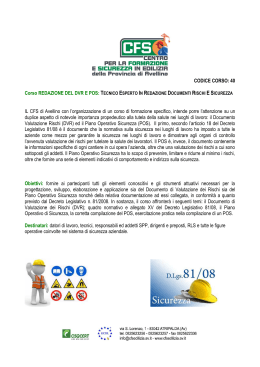
Libretto Istruzioni Uso e Manutenzione
Instructions Manual for the Use and Maintenance
DECERATORE PER CILINDRI
DEWAXER FOR CYLINDERS
DECERA
DECERA
CE
ATTENZIONE: Il presente libretto deve sempre accompagnare l’apparecchio
WARNING: This manual must always accompany the machine
TECNO-GAZ
DENTAL AND MEDICAL EQUIPMENT
TECNO-GAZ La ringrazia di aver acquistato un prodotto della sua gamma e la invita
alla lettura, in ogni parte del presente Manuale Istruzione.
All’interno troverà tutte le istruzioni necessarie per un corretto utilizzo del prodotto. Si
prega di seguire attentamente le avvertenze contenute, di conservarlo inalterato,
facilmente reperibile ed accessibile all’operatore.
Il contenuto del presente Manuale può essere modificato, senza preavviso ne ulteriori
obblighi, al fine di includere variazioni e miglioramenti.
È vietata la riproduzione o la traduzione di qualsiasi parte del presente manuale senza
il consenso scritto di TECNO-GAZ.
La informiamo che la ns. Ditta rimane a Sua completa disposizione per fornire notizie e
delucidazioni in merito a tutto quanto concerne l’utilizzo del prodotto.
Grazie e buon lavoro
TECNO-GAZ S.p.A.
TECNO-GAZ wishes to thank you for your purchasing one of its range of products and
you are invited to read this booklet thoroughly.
This booklet contains all of the information necessary to use the product correctly.
Please adhere closely to the notices contained within and conserve the booklet, without
making changes, in a place where it is easy to find and is accessible to the operator.
The contents of this manual can be changed, without warning or additional obligations,
so that the manufacturer can include variations and improvements.
It is prohibited to copy or translate any of this booklet without the written permission of
TECNO-GAZ.
Our Company remains at your complete disposal to provide any kind of information you
may need for operating the appliance.
Again thank you and good work.
TECNO-GAZ S.p.A.
1
DFDE001 – Rev. 0
INDICE - INDEX
ITALIANO
7 - 19
ENGLISH
20 - 32
2
DFDE001 – Rev. 0
PAR. 01
DICHIARAZIONE CE DI CONFORMITA’
ECC CONFORMITY STATEMENT
La sottoscritta – The company:
TECNO-GAZ S.r.l., Str. Cavalli n. 4 - CAP 43038 Sala Baganza (Parma) ITALIA
DICHIARA SOTTO LA PROPRIA RESPONSABILITA' CHE IL: DECERATORE PER CILINDRI
DECLARES UNDER ITS OWN RESPONSABILITY THAT THE EQUIPMENT: DEWAXER FOR
CYLINDERS
Modello – Model: DECERA
Articolo – Serial number: 6015/D
INCOLLARE TARGHETTA IN ALLUMINIO
STICK ALLUMINIUM PLATE
Costruito dalla ditta – Manufactured by: TECNO-GAZ;
è conforme alle disposizioni legislative che traspongono la direttiva Compatibilità
Elettromagnetica 89/336/CEE e la Direttiva Bassa Tensione 73/23/CEE e loro successivi
emendamenti e modifiche.
complies with the regulations in force regarding the Electromagnetic Compatibility Directive
89/336/EEC and the Low Tension Directive 73/23/EEC and their relative amendments and
modifications.
NOME - NAME: PAOLO BERTOZZI
POSIZIONE: Presidente del Consiglio di amministrazione
POSITION: President of the Board of Directors
Sala Baganza, lì 7 Gennaio 1998
Sala Baganza, 7 January 1998
Firma & Timbro - Sign & Stamp
3
DFDE001 – Rev. 0
PAR. 02
MARCATURA CE
EEC MARKING
PAR. 03
ELENCO PUNTI VENDITA E ASSISTENZA TECNICA ITALIA
LIST OF RETAILERS AND TECHNICAL ASSISTANCE SERVICES IN ITALY
Per informazioni sui punti assistenza e vendita rivolgersi al proprio rivenditore o direttamente
alla ditta TECNO-GAZ:
For information regarding assistance services and retailers please contact your retailer or
directly TECNO-GAZ Company:
TEL.+39 0521 83.39.26 - FAX:+39 0521 83.33.91
http:\\www.tecnogaz.com - e-mail: [email protected]
P.S.:
L’ASSISTENZA TECNICA E’ SVOLTA DIRETTAMENTE DAI CONCESSIONARI
TECNO-GAZ.
P.S.:
TECHNICAL ASSISTANCE IS DIRECTLY CARRIED OUT BY THE TECNO-GAZ
CONCESSIONAIRE.
4
DFDE001 – Rev. 0
PAR. 04
GARANZIA
L'apparecchio è coperto da garanzia, per un periodo di dodici mesi ad esclusione delle parti
elettrice e di riscaldamento, per le quali la garanzia è di sei mesi. Detta garanzia ha inizio dalla
data di consegna del apparecchio al cliente, comprovata dalla restituzione del tagliando di
garanzia debitamente compilato, timbrato e firmato dal rivenditore. In caso di contestazione,
viene ritenuta valida la data indicata sulla bolla di vendita. La riparazione o la sostituzione in
garanzia di un particolare, viene effettuata ad insindacabile giudizio della casa e non
comprende, la trasferta del personale e le spese di imballagio e trasporto.
Sono escluse dalla garanzia lampade, fusibili, vetrerie ed i guasti o danni derivati da una cattiva
manutenzione, negligenza, imperizia o altre cause non imputabili al costruttore. I componenti
soggetti a normale usura e gli accessori non sono compresi nella garanzia. Non è riconosciuto
il diritto alla sostituzione del apparechio completo. La garanzia non comporta alcun
risarcimento danni diretti o indiretti di qualsiasi natura verso persone o cose, dovuti alla
eventuale inefficenza dell'apparecchio. Non viene riconosciuto nessun risarcimento per fermo
macchina. La garanzia decade automaticamente qualora l'apparecchio venga manomesso,
riparato o modificato dall'acquirente o da terzi non autorizzati.
Per gli interventi, l'acquirente deve rivolgersi unicamente al rivenditore oppure ai centri di
assistenza indicati dal costruttore. I componenti sostituiti in garanzia devono essere restituiti
alla TECNO-GAZ in porto franco. La mancata restituzione, comporta l'addebito del costo del
particolare al richiedente.
WARRANTY
The device is covered by the warranty for a period of twelve months excluding electric
components and those of the heating system which have a warranty period of six months. This
warranty begins the date the device is delivered to the client, proved by the warranty coupon
which has to be returned properly filled in, stamped and signed by the retailer. Repairing and
replacement under warranty conditions of any components will be carried out exclusively by
techno-gaz; the warranty does not cover travel expenses of personnel, neither packaging and
transport expenses.
The warranty does not cover lamps, fuses, glassworks and the failures or damages caused by
5
DFDE001 – Rev. 0
wrong maintenance, negligence, unskilfullsness or any other causes the constructor is not to
be hold responsable for. Those materials subjected to regular wearing out are excluded from
the warranty. TECNO-GAZ does not recognize the right to have the whole machine replaced.
The warranty does not meet the request of indemnity for direct or indirect damages, caused to
goods and persons, provoked by the inefficiency of the device. TECNO-GAZ will not
recognized any indemnity in case the machine is not used. The warranty will be automatically
declined in case the machine is tampered, repaired or modified by the client or by third parties
having not been authorized by tecno-gaz.
The purchaser is compelled to contact the retailer or after-sales service centres indicated by
TECNO-GAZ for the repairing. The components replaced during the warranty period must be
sent back to TECNO-GAZ porto franco. In case the replaced components are not be sent back
to TECNO-GAZ the purchaser will be charged for them.
6
DFDE001 – Rev. 0
INDICE PARAGRAFI E FIGURE
01 DICHIARAZIONE DI CONFORMITA’
pag.
3
02 MARCATURA CE
pag.
4
03 ELENCO PUNTI VENDITA E ASSITENZA TECNICA ITALIA
pag.
4
04 GARANZIA
pag.
5
05 CARATTERISTICHE TECNICHE
pag.
8
pag.
9
07 IMPIEGO DELL'APPARECCHIO
pag.
9
08 DESCRIZIONE DELL'APPARECCHIO
pag.
10
09 FIGURA DELL'APPARECCHIO
pag.
11
10 ISTRUZIONI PER L'ISTALLAZIONE
pag.
12
11 ELENCO COMANDI
pag.
12
12 FUNZIONAMENTO
pag.
13
13 SITUAZIONI PERICOLOSE DURANTE IL FUNZIONAMENTO
pag.
15
14 EMISSIONI DI SOSTANZE NOCIVE DURANTE IL FUNZIONAMENTO
pag.
15
15 LAVORAZIONI MANUALI CHE POSSONO CAUSARE DANNI
pag.
16
16 ACCESSORI PER PROTEGGERE L'OPERATORE
pag.
16
17 SCHEMA IMPIANTO ELETTRICO
pag.
17
18 ELENCO COMPONENTI IMPIANTO ELETTRICO
pag.
17
19 AVVERTENZE, CONSIGLI E NOTIZIE UTILI
pag.
18
20 ISTRUZIONI PER LA DEMOLIZIONE DELL'APPARECCHIO
pag.
19
21 AVVERTENZE, CONSIGLI E NOTIZIE UTILI
pag.
19
08 ISTRUZIONI PER L'IMBALLAGGIO, LO STOCCAGGIO, IL TRASPORTO ED
IL SOLLEVAMENTO
7
DFDE001 – Rev. 0
PAR. 05
CARATTERISTICHE TECNICHE
MECCANICHE
ALTEZZA
220mm
LUNGHEZZA
300mm
LARGHEZZA
200mm
PESO
6Kg
MATERIALE
ACCIAIO INOX AISI 304
DIMENSIONI UTILI DELLA CAMERA:
ALTEZZA
75mm
LUNGHEZZA
220mm
LARGHEZZA
120mm
CAPACITA' BACINELLA ACQUA
1.6 Lt.
ELETTRICHE
TENSIONE DI ALIMENTAZIONE
220V
FREQUENZA
50Hz
FASI
1+Neutro
CORRENTE FUSIBILE
4A
POTENZA ASSORBITA
0.7 KW
TIPO DI PROTEZIONE
PE
CLASSE
1
CAVO DI ALIMENTAZIONE mt.2
2x1.5mmq+T
CONNETTORE
16A+Terra
8
DFDE001 – Rev. 0
PAR. 06
ISTRUZIONI PER L'IMBALLAGGIO, LO STOCCAGGIO, IL TRASPORTO
ED IL SOLLEVAMENTO
L'apparecchio DECERA, ha un peso esiguo ed un volume contenuto, perciò non ha bisogno di
un imballaggio particolare.
Protetto da un sacchetto di cellophane, viene posto in un involucro di polistirolo espanso ed
inserito in un contenitore di cartone ondulato e sigillato con nastro adesivo.
Il trasporto deve avvenire senza scosse ed urti e senza esporre il contenitore all'umidità.
ATTENZIONE:
Non disperdere il materiale di imballaggio nell'ambiente, recuperare i prodotti riciclabili ed
affidare i rimanenti ad una impresa di smaltimento rifiuti.
Gli apparecchi imballati devono essere custoditi in luoghi asciutti e ad una temperatura
compresa tra i -10°C e +40°C.
E' consentita la sovrapposizione di più apparecchi.
PAR. 07
IMPIEGO DELL'APPARECCHIO
DECERA è un apparecchio che serve per sciogliere il modellato in cera dei cilindri ; da
impiegarsi
esclusivamente nel settore odontotecnico.
Non e' consentito l'uso dell'apparecchio per altri scopi o in ambienti non pertinenti alle
caratteristiche
di DECERA.
ATTENZIONE.
L'apparecchio DECERA, non scioglie i preformati termoplastici.
9
DFDE001 – Rev. 0
PAR. 08
DESCRIZIONE DELL'APPARECCHIO
Il deceratore, è un apparecchio di piccole dimensioni costituito da due parti:
A) Il mobile, pos.51 pag.8.
B) Il pannello comandi, pos. 52, pag. 8.
Nel mobile vi è alloggiata la bacinella che contiene i seguenti accessori:
Pos. 56, la protezione della resistenza.
Pos. 57, il raccoglicera.
Pos. 58, la griglia portacilindri.
Pos. 61, il coperchio.
Una resistenza elettrica, pos.6 ,posta nella parte inferiore della bacinella, produce il calore
necessario per l'ebollizione dell'acqua.
Il controllo della temperatura e' affidato al bulbo del termostato posto sopra la resistenza
stessa.
Il pannello comandi, contiene l'equipaggiamento elettrico per il controllo della temperatura
(termostato a bulbo) pos. 3-4-5, l'interruttore generale pos. 1 e la spia di emergenza pos. 12.
10
DFDE001 – Rev. 0
PAR. 09
FIGURA APPARECCHIO
11
DFDE001 – Rev. 0
PAR. 10
ISTRUZIONI PER L'INSTALLAZIONE
Il deceratore per cilindri "DECERA", deve essere sistemato su di un piano orizzontale, sotto una
cappa aspirante o in un luogo ben ventilato.
Inserire la spina di alimentazione elettrica pos. 11, in una presa di corrente monofase alternata
ad una tensione di 220V 50Hz.
Detta presa deve erogare una potenza di 1 KW, essere munita di protezione di terra e di
dispositivo salvavita.
PAR. 11
ELENCO COMANDI
IL PANNELLO COMANDI, Pos. 52, Pag. 8, COMPRENDE I SEGUENTI COMPONENTI:
A) Pos.1
Interruttore generale .
B) Pos.5
Termostato per il controllo e la regolazione della temperatura della resistenza.
C) Pos.12
Spia che indica l'intervento del termostato e quindi la situazione di emergenza,
CAUSATA DALLA MANCANZA DI ACQUA NELLA BACINELLA.
12
DFDE001 – Rev. 0
PAR. 12
FUNZIONAMENTO
Come detto nel par. 06,pag. 6, DECERA è un apparecchio che serve per sciogliere i modellati
in cera dei cilindri.
Per sciogliere la cera, bisogna somministrare calore ai cilindri ad una temperatura, costante,
che permetta la liquefazione del materiale senza bruciarlo.
Per ottenere quanto sopra, TECNO GAZ, ha adottato il sistema di riscaldamento a vapore, che
consente lo svolgimento del trattamento alle condizioni suddette.
Per decerare i cilindri bisogna:
A) Togliere il coperchio pos. 61, pag. 8 ed il raccoglicera con la griglia portacilindri, pos. 5758.
B) Mettere nella bacinella, pos. 60, acqua di rubinetto o demineralizzata.
Il livello dell'acqua nella bacinella è rappresentato dalla parte superiore della
protezione resistenza, pos. 56; l'acqua deve arrivare al filo della superficie suddetta.
fig. A, pag. 8.
C) Disporre i cilindri sulla griglia pos. 58, contenuta nel raccoglicera pos. 57.
I cilindri debbono essere messi in verticale, con i canali di colata rivolti verso la griglia e
non debbono debordare dal raccoglicera, fig. B, pag. 8.
D) Mettere il lavoro cosi' composto nella bacinella e chiudere con il coperchio posizionando il
foro di sfogo del vapore dalla parte opposta al pannello comandi.
E) Regolare, con la manopola pos. 3, il termostato alla temperatura di 120°C.
L'acqua deve bollire continuamente per produrre il vapore necessario per fondere la
cera.
F)
Azionare l'interruttore generale pos. 1, per avviare il trattamento.
DECERA impiega quindici minuti circa, per raggiungere l'ebollizione dell'acqua.
La durata del trattamento dipende dal tipo di cera impiegata, dalle dimensioni di ogni
singolo cilindro e soprattutto dal diametro dei canali di colata dai quali deve defluire la
cera.
Il tempo di deceratura a pieno carico, con N° 2 cilindri 9X, è di 70 minuti circa, compreso il
tempo di ebollizione.
Con un pieno carico di cilindri 1X, detto tempo si riduce a 40 minuti, compreso il tempo di
ebollizione.
13
DFDE001 – Rev. 0
I dati suddetti sono puramente indicativi e non rappresentano certezze applicabili ai
diversi metodi di impernatura.
Solo con l'esperienza, l'operatore puo' stabilire con certezza il tempo di trattamento per
ogni singolo lavoro.
L'autonomia di acqua di DECERA è di 60 minuti circa, in condizioni ottimali.
Se si deve prolungare il tempo di trattamento, bisogna aggiungere acqua come indicato
nel par. 17 pag. 15, punto H-I.
G) Terminato il trattamento, spegnere l'apparecchio con l'interruttore generale pos. 1 e
attendere alcuni minuti per fare condensare il vapore.
H) Mettere i guanti, togliere il coperchio della bacinella ed estrarre il raccoglicera usando le
apposite maniglie, vedi figura pag. 8.
I)
Toglire i cilindri dalla griglia , rimuovere la cera che si e' depositata nel raccoglicera e pulire
gli accessori.
Questa operazione si deve fare alla fine di ogni trattamento .
L)
Controllare il livello dell'acqua nella bacinella ,come da punto B); aggiungerne se
necessario.
Inserire gli accessori e chiudere con il coperchio.
DECERA è pronto per un altro trattamento.
Per ulteriori dettagli circa l'uso e la manutenzione dell'apparecchio, vedere il par. 17 pag. 15.
14
DFDE001 – Rev. 0
PAR. 13
SITUAZIONI PERICOLOSE DURANTE IL FUNZIONAMENTO
A) Interruzione dell'energia elettrica.
Se viene a mancare l'energia elettrica durante la fase di lavoro, DECERA si spegne e si
raffredda.
Al ripristino dell'energia elettrica si mette in funzione regolarmente, recuperando il calore
perso.
B) Mancanza di acqua.
La mancanza o l'abbassamento del livello dell'acqua, sotto la posizione della resistenza,
determina l'aumento della temperatura di questa.
Il termostato interviene, toglie l'alimentazione elettrica alla resistenza ed avvisa,
accendendo la spia "DANGER" pos. 12, della situazione di pericolo.
Questa sicurezza è temporanea, appena la temperatura della resistenza diminuisce,
scendendo sotto al valore impostato sul termostato, la resistenza si riaccende.
Quanto sopra si ripete finché viene ripristinato il livello dell'acqua nella bacinella.
La situazione suddetta, a lungo andare, compromette il funzionamento e la durata
dell'apparecchio.
L'operatore deve sorvegliare, costantemente, il funzionamento dell'apparecchio.
PAR. 14
EMISSIONI DI SOSTANZE NOCIVE
Durante il fuzionamento, dal DECERA,viene emesso vapore acqueo e gas derivanti dai
modellati in cera contenuti nei cilindri. Come già detto nei paragrafi precedenti si consiglia di
usare il DECERA sotto una cappa aspirante.
TECNO GAZ NON E' RESPONSABILE DEI DANNI PRODOTTI A PERSONE O COSE DOVUTI
ALLA NEGLIGENZA O IMPERIZIA DELL'OPERATORE.
15
DFDE001 – Rev. 0
PAR. 15
LAVORAZIONI MANUALI CHE POSSONO CAUSARE DANNI
Tutte le operazioni manuali riguardanti la decerazione dei cilindri, possono essere causa di
incidenti di natura termica.
Non è possibile proteggere l'operatore da questi rischi, perché l'impiego di barriere impedisce
l'uso dell'apparecchio. Per evitare o limitare il pericolo di ustioni, l'operatore deve munirsi di
accessori di protezione adeguati.
TECNO GAZ NON E' RESPONSABILE DEI DANNI PRODOTTI A PERSONE O A COSE
DURANTE LO SVOLGIMENTO DELLE OPERAZIONI MANUALI.
PAR. 16
ACCESSORI PER PROTEGGERE L' OPERATORE
L'uso del DECERA richide i seguenti accessori per proteggerre l'operatore:
a) Guanti termici
b) Grambiule termico
Questi acessori non sono fornibili da TECNO GAZ.
Rivolgersi ad un negozio specializzato.
16
DFDE001 – Rev. 0
PAR. 17
SCHEMA IMPIANTO ELETTRICO
PAR. 18
ELENCO COMPONENTI IMPIANTO ELETTRICO
Pos. Q.tà
Descrizione
Cod.
01
1
Interruttore bipolare a bascula, luminoso, verde, protetto 250 V 10 A
CEQ0010
05
1
Termostato a bulbo 16 A 250 V T 0°C / 120°C
CEB0002
06
1
Resistenza elettrica 650 Watt 250 V
SDEA006
08
2
Fusibili da quadro
CEF0004
09
2
Fusibili min. 5x20 4 A
CEF0009
10
1
Pressacavo autobloccante P16 ø 6 mm
CE02021
11
1
Cavo con spina 3x1.5 mm2
CE06001
12
1
Spia luminosa arancio ø 10 mm 250 V
CEH0012
17
DFDE001 – Rev. 0
PAR. 19
AVVERTENZE, CONSIGLI E NOTIZIE UTILI
A) Prima di iniziare il lavoro controllare il livello dell'acqua, aggiungerne se manca, vedi fig. a,
pag. 8.
B) Non superare il livello indicato, l'acqua bolle tumultuosamente, entra nel raccoglicera e fa
fuoriuscire la cera.
C) La quantità totale di acqua da mettere nella bacinella e' di 1.6 lt. circa.
D) Mettere sempre il coperchio.
E) Evitare di togliere frequentemente il coperchio, questa operazione raffredda i cilindri e
consuma piu acqua riducendone l'autonomia.
F)
Mettere nella bacinella solo acqua. Non mettere liquidi o solventi che con il calore possono
produrre situazioni pericolose.
G) Durante il trattamento dei cilindri, l'acqua, contenuta nella bacinella, si trasforma in vapore
e diminuisce di livello. Il tempo per passare dal livello massimo a quello minimo
(autonomia), è 60 minuti circa.
H) Trascorsi i sessanta minuti di autonomia,se si intende proseguire con il trattamento,
bisogna aggiungere subito 1/2 lt. di acqua nella bacinella e ripetere l'operazione dopo ogni
40 minuti, circa, di proseguimento del ciclo.
I)
Per aggiungere l'acqua durante il funzionamento, bisogna munirsi di un contenitore di
plastica che possa contenere la quantita' di acqua stabilita e avente un orifizio piccolo
(peretta). Appoggiare la bocca del contenitore alla parete della bacinella, quindi
comprimendo il contenitore, far scivolare l'acqua lungo la parete della bacinella. Fare
attenzione che il raccoglicera non sia a contatto con la bacinella nel punto in ciu si fa
scendere l'acqua.
L)
Lasciare sempre il termostato regolato alla temperatura di 120°C; ad una temperatura
inferiore l'acqua non bolle continuamente, non produce vapore e quindi la cera non fonde.
M) L'altezza massima dei cilindri da mettere nel deceratore è di 70 mm.
N) I cilindri non debbono debordare dal raccoglicera perche' la cera fusa cola nell'acqua e a
contatto con la resistenza brucia; specialmente quando il livello si abbassa.
18
DFDE001 – Rev. 0
PAR. 20
ISTRUZIONI PER LA DEMOLIZIONE DELL'APPARECCHIO
DECERA è costruito con materiali ferrosi e componenti elettromeccanici non pericolosi.
Quando l'apparecchio viene demolito, non vi sono particolari istruzioni da seguire, l'acciaio
inox è totalmente riciclabile ed i rimanenti componenti debbono essere affidati alle imprese di
smaltimento.
NON ABBANDONARE L'APPARECCHIO IN LUOGHI NON CUSTODITI O IN POSIZIONI
PERICOLOSE.
PAR. 21
AVVERTENZE-CONSIGLI E NOTIZIE UTILI
A)
Controllare ogni volta che si usa il decera il livello dell'acqua aggiungere se manca.
B)
Mettere il coperchio.
C)
Evitare di togliere frequentemente il coperchio, questa operazione diminuisce il tempo di
autonomia dell' apparecchio.
D)
L'altezza max dei cilindri trattabili nel deceratore e' di 60mm, si possono trattare cilindri di
70-75mm avendo l' avvertenza di sistemarli ai lati dell' impugnatura coperchio.
19
DFDE001 – Rev. 0
INDEX OF PARAGRAPHES AND PICTURES
01 ECC CONFORMITY STATEMENT
3
02 EEC MARKING
4
03 LIST OF RETAILERS AND TECHNICAL ASSISTANCE SERVICES IN ITALY
4
04 WARRANTY
5
05 TECHNICAL FEATURES
21
06 INSTRUCTIONS FOR PACKAGING, STORAGE, TRANSPORT AND HOISTING
22
07 INTENDED USE OF EQUIPMENT
22
08 DESCRIPTION OF THE EQUIPMENT
23
09 EQUIPMENT’S PICTURE
24
10 INSTRUCTIONS FOR THE INSTALLATION
25
11 CONTROLS LIST
25
12 OPERATING INSTRUCTIONS
26
13 DANGERUOS SITUATIONS DURING OPERATIONS
28
14 HARMFUL SUBSTANCES EMITTED BY THE EQUIPPEMENT
28
15 MANUAL OPERATIONS THAT MAY CAUSE DAMAGES
29
16 SAFETY EQUIPMENT FOR THE OPERATOR
29
17 ELECTRICAL SYSTEM DIAGRAM
30
18 LIST OF THE ELECTRICAL SYSTEM COMPONENTS
30
19 WARNING, SUGGESTIONS AND USEFUL INFORMATION
31
20 ISTRUCTIONS FOR THE EQUIPMENT DEMOLITION
32
21 WARNING, SUGGESTIONS AND USEFUL INFORMATION
32
20
DFDE001 – Rev. 0
PAR. 05
TECHNICAL FEATURES
MECHANICAL FEATURES
HEIGHT
220mm
LENGHT
300mm
WIDTH
200mm
WEIGHT
6Kg
MATERIAL
STAINLESS STEEL AISI 304
USEFUL DIMENSIONS OF THE COMPARTMENT:
HEIGHT
75mm
LENGHT
220mm
WIDTH
120mm
WATER TRAY CAPACITY
1.6 Lt.
ELECTRICAL FEATURES
POWER SUPPLY
220V
FREQUENCY
50Hz
PHASES
1+Neutral
FUSE CURRENT
4A
ABSORBED POWER
0.7 KW
TYPE OF PROTECTION
PE
CLASS
1
SUPPLY CABLE mt.2
2x1.5mmq+T
CONNECTOR
16A+ ground
21
DFDE001 – Rev. 0
PAR. 06
INSTRUCTION FOR PACKAGING, STORAGE, TRANSPORT AND HOISTING
The equipment DECERA does not need any special packaging since it is very small and its
weight is very low.
The equipment is sent protected by a cellophane bag, wrapped in a foam polystyrene cover,
placed within a corrugated cardboard box and sealed with adhesive tape.
ATTENTION: Do not abandon packaging material in the environment, recover all those
materials that can be recycled and entrust any the other products to a company specialized in
disposing of waste.
The packed equipment has to be kept in a dry place and at a temperature compressed
between -10°C and +40°C.
It is allowed to pack the equipment one on top of other.
PAR. 07
INTENDED USE OF EQUIPMENT
DECERA is a device used to melt the cylinders’ was moulds; to be used only for dental
technology.
It is not allowed to use the device for other purpose or in environment different from those the
DECERA has been manufactured for.
ATTENTION.
The device DECERA does not melt thermoplastic stamps.
22
DFDE001 – Rev. 0
PAR. 08
DESCRIPTION OF THE EQUIPMENT
The dewaxer is a very small device composed by two parts:
A) The piece of furniture, pos.51 pag.8.
B) The control board, pos. 52, pag. 8.
The piece of furniture houses a tray that contains the following equipment:
Pos. 56, thermal resistance’s protection.
Pos. 57, wax-holder.
Pos. 58, cylinder-holders’ grid.
Pos. 61, the cover.
A thermal resistance, pos.6 , located on the lower part of the tray, produces the necessary heat
to boil the water.
The temperature is controlled by the bulb thermostat mounted over the resistance.
The control board contains the electrical equipment necessary to control the temperature (bulb
thermostat) pos. 3-4-5, general switch pos. 1 and the emergency pilot light pos. 12.
23
DFDE001 – Rev. 0
PAR. 09
EQUIPMENT’S PICTURE
24
DFDE001 – Rev. 0
PAR. 10
INSTRUCTION FOR THE INSTALLATION
The dewaxer for cylinders "DECERA", has to be placed on an horizontal plane, under a
suctioning hood or in a well ventilated area.
Connect the electric power plug pos. 11 to an alternate monophase outlet having a voltage of
220V 50Hz.
This outlet has to supply 1 KW power, it has also to be equipped with an earthing wire and a
safety device.
PAR. 11
CONTROLS LIST
THE CONTROL BOARD, Pos. 52, Pag. 8, INCLUDES THE FOLLOWING ELEMENTS:
A) Pos.1
General switch.
B) Pos.5
Thermostat for controlling and regulating the resistance’s temperature.
C) Pos.12
Pilot light that shows the thermostat is energized and therefore the presence of
an emergency situation CAUSED BY THE LACK OF WATER INSIDE THE TRAY.
25
DFDE001 – Rev. 0
PAR. 12
OPERATING INSTRUCTIONS
DECERA, as already described in par. 06 of pag. 6 is an equipment meant for melting
cylinders’ wax moulds.
To melt the wax it is necessary to heat the cylinders to such an steady temperature that allows
the material to get melted without burning.
To obtain such a process, TECNO GAZ has adopted a steam heating system that allows the
treatment to be carried out as described.
To dewax the cylinder it is necessary to carry out the following instructions:
A) Remove the cover pos. 61, pag. 8 and the wax-holder with the cylinder-holders grid pos.
57-58.
B) Fill in the tray, pos. 60, with tap water or demineralized water.
The level of the water admitted in the tray is indicated by the superior part of the
resistance’s protection, pos. 56; the tray has to be filled with water up to the abovementioned surface. fig. A, pag. 8.
C) Arrange the cylinders on the grid pos. 58, lodged in the wax-holder pos. 57.
The cylinders have to be placed in vertical position, with the casting channels turned to the
grid and should not come out from the wax-holder, fig. B, pag. 8.
D) Put the so composed group in the tray and close the cover; position the steam outlet hole
to the opposite part of the control board.
E) Regulate, using the handle pos. 3, the thermostat to a temperature of 120°C.
The water have to boil continuously in order to produce the necessary steam needed
to melt the wax.
F)
Switch on the general switch, pos. 1, to start the treatment.
It takes DECERA more or less fifteen minutes to make the water boil.
The time of the treatment depends on the type of wax used, on the dimension of every
single cylinder and specially on the diameter of the casting channels from which the wax
flow out.
The fully loaded dewax time, with N° 2 cylinders 9X, is about 70 minutes, included the
boiling time.
The fully loaded dewax time for cylinders 1X is reduced to 40 minutes, included the boiling
time.
26
DFDE001 – Rev. 0
The above mentioned data is just indicative and does not represent any certainty
applicable to the several pivoting methods.
Only the experience tells the operator which is the better treatment’s time for every single
case.
DECERA HAS a water autonomy of about 60 minutes, in optimal conditions.
If you need to extend the treatment time, it will be necessary to add water as described in
par. 17 pag. 15, point H-I.
G) Once the treatment has finished, switch off the general switch pos. 1 and wait some
minutes for the steam to become condensation.
H) Put on the gloves, remove the tray cover and take off the wax-holder using the special
handles; see figure in pag. 8.
I)
Take away the cylinders from the grid, remove the wax that is deposited in the wax-holder
and clean the equipment.
These operations have to be carried out at the end of every treatment.
L)
Control the level of water in the tray as described in point B); if necessary add water.
Replace the equipment in position and close the cover.
DECERA is ready to carry out another treatment.
For further information about the use and maintenance of the device, see par. 17 pag. 15.
27
DFDE001 – Rev. 0
PAR. 13
DANGEROUS SITUATIONS DURING THE FUNCTIONING
A) Interruption of the power supply.
If power supply fails while the device is operating, DECERA goes off and get cold.
When the power supply is restored the equipment start working regularly, getting warm
again.
B) Lack of water.
The lack of water or the lowering of the water level under the position of the resistance
increases of the resistance’s temperature.
The thermostat gets engaged, cuts off the power supply to the resistance and signals the
danger situation by lighting the pilot light “DANGER” pos.2.
This safety situation is only temporary; no sooner the resistance’s temperature
decreases, falling under the value set on the thermostat, the resistance goes on
again.
This situation will keep repeating till the correct level of water in the tray has been
refilled.
If the above mentioned situation often happen, in time it could compromise the
equipment’s functioning and its working life.
The operator has continuously to control the device’s functioning.
PAR. 14
HARMFUL SUBSTANCES EMITTED BY THE EQUIPMENT
During operations steam and gas come out from the wax moulds contained in the cylinders.
As already described in the previous paragraphs, it is convenient to place and use DECERA
under a suction hood.
TECNO-GAZ WILL NOT TO BE HOLD RESPONSABLE FOR DAMAGES TO PERSONS OR
GOODS CAUSED BY NEGLIGENCE OR UNSKILFULNESS OF THE OPERATOR.
28
DFDE001 – Rev. 0
PAR. 15
MANUAL OPERATIONS THAT MAY CAUSE DAMAGES
All the manual operations regarding the cylinders’ dewaxing, can be the cause of accidents of
thermal nature.
It is not possible to protect the operator from these risks as the use of protective barriers do not
allow the use of the device.
To avoid or limit burnings, the operator must wear suitable protective equipment.
TECNO-GAZ WILL NOT TO BE HOLD RESPONSABLE FOR DAMAGES TO PERSONS OR
GOODS DURING MANUAL OPERATIONS.
PAR. 16
SAFETY EQUIPMENT FOR THE OPERATOR
The operator should wear the following safety equipment while using DECERA:
a) Thermal gloves
b) Thermal apron
These equipment is not supplied by TECNO-GAZ.
Please contact a specialized retail.
29
DFDE001 – Rev. 0
PAR. 17
ELECTRICAL SYSTEM DIAGRAM
PAR. 18
LIST OF THE ELECTRICAL SYSTEM COMPONENTS
Pos. Q.ty
Description
Cod.
01
1
Bipolar platform balance switch, luminous, green, protected 250 V 10 A
CEQ0010
05
1
Bulb thermostat 16 A 250 V T 0°C / 120°C
CEB0002
06
1
Electric resistance 650 Watt 250 V
SDEA006
08
2
Board fuses
CEF0004
09
2
Fuses min. 5x20 4 A
CEF0009
10
1
Self blocking wire-inlet P16 ø 6 mm
CE02021
11
1
Cable with plug 3x1.5 mm2
CE06001
12
1
Orange luminous pilot light ø 10 mm 250 V
CEH0012
30
DFDE001 – Rev. 0
PAR. 19
WARNINGS, SUGGESTIONS AND USEFUL INFORMATION
A) Before starting operations, check the level of water and refill if necessary, see fig. a, pag. 8.
B) Do not fill over the indicated level, since the water boils tumultuosly, it will enter in the waxholder and push the wax out.
C) The total amount of water to fill in the tray is about 1.6 lt.
D) Always close the cover.
E) Avoid taking often off the cover, since this operation makes the cylinders cool down and
the device uses more water so reducing its autonomy.
F)
Fill the tray only with water. Do not use liquids or solvents which getting heated up can
provoke dangerous situations.
G) During the treatment of the cylinders, the water contained in the tray, becomes steam and
the level decreases. The time neede to pass from the maximum level to the minimum one
(autonomy) is of about 60 minutes.
H) When the sixty minutes of autonomy are over, and if you intend to continue with the
treatment, it will be necessary to add inmediately 1/2 lt. of water in the tray and repeat the
refilling operation more or less every 40 minutes.
I)
To add water during operations, it is necessary to use a plastic container capable of
containing the established quantity of water, and having a little hole (rubber ball). Lean the
opening of the container on the wall of the tray, then pres the container to make the water
slide along the wall of the tray. Pay attention that the wax-holder does not touch the tray on
the point where the water flows down.
L)
Leave always the thermostat regulated at the temperature of 120°C; if the thermostat is set
to a lower temperature the water will not boil continuously, it will not produce steam and
therefore the wax will not melt.
M) The maximum hight of the cylinders to be placed in the dewaxer is of 70 mm.
N) The cylinders should not surpass the wax-holder limits as the melted wax will drop in the
water and burn out when touching the resistance; specially when the level falls down.
31
DFDE001 – Rev. 0
PAR. 20
INSTRUCTIONS FOR THE EQUIPMENT DEMOLITION
There are not particular instruction regarding the demolition and disposal of this equipment
since stainless steel is quite recyclable and the remaining components have to be entrusted to
the company specialized in disposing of these materials.
DO NOT LEAVE THE DEVICE IN UNATTENDED PLACES OR IN DANGEROUS POSITIONS.
PAR. 21
WARNINGS-SUGGESTIONS AND USEFUL INFORMATION
A)
EVERYTIME YOU USE THE DEVICE CHECK THE WATER LEVEL, IF IS NOT ENOUGH
REFILL IN THE WATER.
B)
PUT ON THE COVER.
C)
AVOID TAKING OFF OFTEN THE COVER, THIS OPERATION REDUCES THE
AUTONOMY TIME OF THE DEVICE.
D)
THE MAX HEIGT OF CILINDERS THE MACHINE CAN TREAT IN THE DEWAXER IS OF
60mm; CILINDERS OF 70-75mm CAN BEEN TREATED TAKING CARE TO PLACE THEM
ON THE SIDE OF THE COVER’S HANDLE.
32
DFDE001 – Rev. 0
DIGIgraph - PR
TECNO-GAZ S.p.A.
DENTAL AND MEDICAL EQUIPMENT
Strada Cavalli, 4 - 43038 Sala Baganza, Parma, Italia
Tel. +39 0521 83.39.26 - Fax +39 0521 83.33.91
http: www.tecnogaz.com - e-mail: [email protected]
Scarica