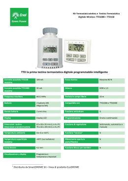
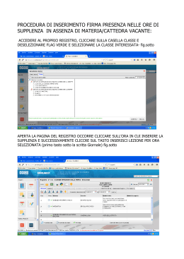
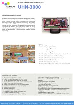
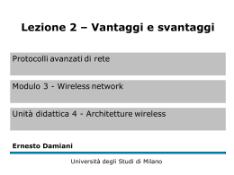
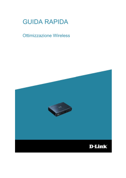
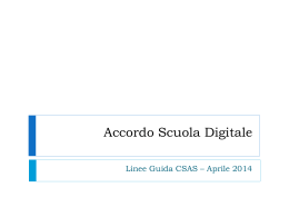
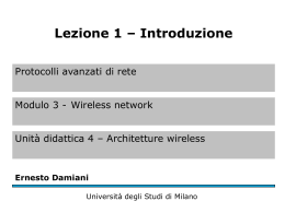
I
1
1.1
GENERALITÁ
OVERVIEW
INFORMAZIONI GENERALI
GENERAL INFORMATION
Questo manuale è stato concepito con l’obbiettivo di fornirVi tutte le spiegazioni per essere in
grado di gestire al meglio il Vostro sistema di
climatizzazione.Vi invitiamo quindi a leggerlo
attentamente prima di mettere in funzione
l’apparecchio.
This manual aims to provide you with all the
information you need to get the most out of your
air conditioning unit. Please read it carefully
before starting to use your appliance.
Leggere attentamente il presente manuale
prima di procedere con qualsiasi operazione
(installazione, manutenzione, uso) ed attenersi scrupolosamente a quanto descritto nei
singoli capitoli; Olimpia Splendid garantisce
questo dispositivo per difetti imputabili a vizi
di fabbricazione in conformità al D.L. 24/02
del 02/02/2002.
Resta escluso dalla garanzia qualsiasi altro
problema legato a:
- errata installazione
- eventi atmosferici straordinari
- dimensionamento non conforme
- manomissioni da parte di personale non
autorizzato
- sostituzione delle batterie esaurite.
Read this manual carefully before carrying out
any operation (installation, maintenance or
use) and make sure the instructions contained
in each section are scrupulously followed.
In conformity with Legislative Decree 24/02
dated 02/02/2002, Olimpia Splendid guarantees this device against defects attributable
to production faults. Problems related to the
following are not covered by the guarantee:
- improper installation
- extraordinary atmospheric events
- inaccurate measurement calculations
- tampering by unauthorised personnel
- replacement of worn out batteries.
LA DITTA COSTRUTTRICE NON SI ASSUME
RESPONSABILITÀ PER DANNI A PERSONE
O COSE DERIVANTI DALLA MANCATA OSSERVANZA DELLE NORME CONTENUTE NEL
PRESENTE LIBRETTO.
2
GB
THE MANUFACTURER ASSUMES NO LIABILITY FOR DAMAGES TO GOODS OR PERSONS
RESULTING FROM FAILURE TO COMPLY
WITH THE INSTRUCTIONS CONTAINED IN
THIS MANUAL.
La ditta costruttrice si riserva il diritto di apportare
modifiche in qualsiasi momento ai propri modelli,
fermo restando le caratteristiche essenziali
descritte nel presente manuale.
The manufacturer reserves the right to make any
changes deemed necessary to its models at any
time, it being understood that the main features
described in this manual remain unaltered.
Durante il montaggio, e ad ogni operazione
di manutenzione, è necessario osservare le
precauzioni citate nel presente manuale, ed
adottare ogni precauzione suggerita dal comune
buonsenso e dalle Normative di Sicurezza vigenti
nel luogo d’installazione.
During installation and for all maintenance work,
the safety measures contained in this manual
must be observed, as must all precautions
dictated by common sense and by the safety
regulations in effect where the installation is to
take place.
In caso di sostituzione di componenti utilizzare esclusivamente ricambi originali OLIMPIA
SPLENDID.
In the event of parts replacements, always use
original OLIMPIA SPLENDID spare parts only.
Conservare con cura questo libretto per ogni
ulteriore consultazione.
Dopo aver tolto l’imballaggio assicurarsi
dell’integrità dell’apparecchio; gli elementi
dell’imballo non devono essere lasciati alla
portata dei bambini in quanto potenziali fonti
di pericolo.
Keep this manual in a safe place for future
reference.
After removing the packaging, ensure the
unit is intact.
The packing pieces are potentially harmful
and, as such, should be kept out of reach
of children.
I
GB
SMALTIMENTO
Il simbolo sul prodotto o sulla
confezione indica che il prodotto non deve
essere considerato come un normale rifiuto
domestico, ma deve essere portato nel punto di raccolta appropriato per il riciclaggio di
apparecchiature elettriche ed elettroniche.
Provvedendo a smaltire questo prodotto
in modo appropriato, si contribuisce a
evitare potenziali conseguenze negative per l’ambiente e per la salute, che
potrebbero derivare da uno smaltimento
inadeguato del prodotto.
Per informazioni più dettagliate sul riciclaggio di questo prodotto, contattare l’ufficio
comunale, il servizio locale di smaltimento
rifiuti o il negozio in cui è stato acquistato
il prodotto.
Questa disposizione è valida solamente
negli Stati membri dell’UE.
DISPOSAL
This symbol on the product or its packaging
indicates that the appliance cannot be treated as normal domestic trash, but must be
handed in at a collection point for recycling
electric and electronic appliances.
Yo u r c o n t r i b u t i o n t o t h e c o r r e c t
disposal of this product protects the environment and the health of your fellow men.
Health and the environment are endangered
by incorrect disposal.
Further information about the recycling of
this product can be obtained from your local
town hall, your refuse collection service, or
in the store at which you bought the product.
This regulation is valid only in EU member
states.
SIMBOLOGIA
SYMBOLS
I pittogrammi riportati nel seguente capitolo
consentono di fornire rapidamente ed in modo
univoco informazioni necessarie alla corretta
installazione ed utilizzo dell’apparecchio in
condizioni di sicurezza.
The symbols contained in this chapter provide
quick and clear information for the correct and
safe use and installation of the unit.
Pittogrammi redazionali
Symbols
Service
• Contrassegna situazioni nelle quali si deve
informare il SERVICE aziendale interno:
SERVIZIO ASSISTENZA TECNICA
CLIENTI.
Service
• Indicates situations where the company’s CUSTOMER TECHNICAL SERVICE CENTRE
should be contacted.
Indice
• I paragrafi preceduti da questo simbolo
contengono informazioni e prescrizioni
molto importanti, particolarmente per
quanto riguarda la sicurezza.
Il mancato rispetto può comportare:
• pericolo per l’incolumità degli operatori
• perdita della garanzia contrattuale
• declinazione di responsabilità da parte della
ditta costruttrice.
Index
• Paragraphs marked by this symbol contain
important information and instructions, especially regarding safety.
Failure to comply with them may result in:
• safety hazards for workers
• loss of the contract warranty
• the manufacturer declining all liabilities.
Mano alzata
• Contrassegna azioni che non si devono
assolutamente fare.
Raised hand
• Indicates operations that must not be undertaken for any reason.
Pittogrammi relativi alla sicurezza
Safety related symbols
Pericolo generico
• Segnala al personale interessato che
l’operazione descritta presenta, se non
effettuata nel rispetto delle normative di
sicurezza, il rischio di subire danni fisici.
General danger
• Indicates to those concerned that the operation described may cause physical harm
if not carried out in compliance with safety
regulations.
1
1.2
1.2.1
1.2.2
WIRELESS B1012
3
I
1
1.3
4
GB
USO PREVISTO
INTENDED USE
Il COMANDO A PARETE WIRELESS B1012
consente di controllare il funzionamento del
climatizzatore al quale è abbinato, a seconda
delle impostazioni selezionate e visualizzate sul
display di cui è corredato.
Il COMANDO A PARETE WIRELESS B1012
deve essere utilizzato esclusivamente in
abbinamento all’INTERFACCIA SERIALE
WIRELESS B1011 opportunamente connessa ai
climatizzatori OLIMPIA SPLENDID predisposti.
Tramite questi due componenti abbinati, il
climatizzatore potrà essere attivato in modo da
ottenere una temperatura ambiente pari a quella
impostata sul comando a parete.
The WIRELESS B1012 WALL-MOUNTED
CONTROL PANEL controls the air-conditioner
to which it is associated according to the settings
chosen and shown on the display.
The WIRELESS B1012 WALL-MOUNTED
CONTROL PANEL should only be used with
the WIRELESS B1011 SERIAL INTERFACE
duly connected to OLIMPIA SPLENDID airconditioners equipped for the purpose.
By using these two paired units, the airconditioner can be used in such a way that it
reaches the room temperature set on the wallmounted control panel.
AVVERTENZE
WARNINGS
• Questo apparecchio dovrà essere
destinato solo all’uso per il quale è stato
espressamente concepito, e cioè per
gestire la temperatura negli ambienti dove
viene installato. Ogni altro uso è da
considerarsi improprio e quindi
pericoloso.Il costruttore non può essere
considerato responsabile per eventuali
danni derivanti da usi impropri, erronei ed
irragionevoli.
• In caso di guasto e/o di cattivo funziona mento del sistema, spegnerlo e non
manometterlo. Per l’eventuale riparazione
rivolgersi esclusivamente ai centri di
assistenza tecnica autorizzati dal
costruttore e richiedere l’utilizzo di ricambi
originali. Il mancato rispetto di quanto
sopra può compromettere la sicurezza del
sistema.
• Non permettete che l’apparecchio sia
usato da bambini o da incapaci, senza
sorveglianza.
• In caso di prolungato periodo di inattività
del COMANDO A PARETE WIRELESS
B1012 si consiglia di estrarre le batterie
dall’apposito vano.
• This device should only be used for the
purposes for which it has been expressly
designed, that is to control temperatures in
the rooms where it is installed. All other uses
are inappropriate and therefore dangerous.
The manufacturer shall not be held responsible for possible damages deriving from
improper, incorrect or unreasonable use.
• In the event the system breaks down and/or
malfunctions, turn it off and do not tamper
with it. If repairs are needed, refer to
authorised technical service centres only
and ask that only original spare parts be
used. Failure to comply with the above can
compromise the safety of the system.
• Do not allow the device to be used by children or
persons unable to do so without proper
supervision.
• In the event the WIRELESS B1012 WALL MOUNTED CONTROL PANEL is not to
be used for any length of time, remove the
batteries from their compartment.
I
GB
• In caso di smantellamento del sistema
estrarre le batterie dall’apposito vano e
procedere allo smaltimento differenziato
dei singoli componenti secondo le
disposizioni di legge locali.
Si raccomanda inoltre di rendere
innocue quelle parti dell’apparecchio
suscettibili di costituire un pericolo,
specialmente per i bambini che potrebbero
servirsi dell’apparecchio fuori uso per i
propri giochi.
• For equipment disposal, remove the batteries
from their compartment and follow refuse
collection procedures for individual parts in
accordance with local regulations.
Furthermore, ensure that those parts of
the device which could constitute a danger,
especially for children who might regard
them as toys, are kept safe.
Rendere note a tutto il personale interessato
all’installazione della macchina le presenti
istruzioni.
Make sure all personnel involved in the
installation of the device are made aware of
these instructions.
1
WIRELESS B1012
5
I
2
2.1
GB
INSTALLAZIONE
INSTALLATION
IDENTIFICAZIONE DELLE PARTI PRINCIPALI
MAIN PARTS
1)cornice
2)supporto scheda
3)base
4)batterie
5)tasti funzionali
6)viti fissaggio supporto scheda
7)selettori codifica trasmissione
1)frame
2) card support
3) base
4) batteries
5) function keys
6) card support clamping screws 7) transmission encoding selectors
AVVERTENZE
WARNINGS
L’installazione deve essere eseguita da personale
qualificato.
E’ indispensabile applicare tutte le nozioni precisate nel presente manuale.
La loro mancata applicazione può comportare
malfunzionamenti negli apparecchi non imputabili alla loro qualità e che fanno quindi decadere
ogni forma di garanzia prestata dal costruttore.
Installation must be carried out by qualified
personnel.
All instructions contained in this manual must
be adhered to.
Failure to do so can lead to the malfunctioning
of the units which may not be attributed to their
quality and which would therefore invalidate all
forms of guarantee given by the manufacturer.
1
3
2
7
6
6
5
4
1
I
GB
2
INSERIMENTO BATTERIE
INSERTING THE BATTERIES
I l C O M A N D O A PA R E T E W I R E L E S S
B1012 viene fornito sprovvisto di batterie di
alimentazione. Esse devono essere del tipo AA
(LR6) alcaline a secco da 1,5 V.
The WIRELESS B1012 WALL-MOUNTED
CONTROL PANEL comes without batteries.
They have to be AA (LR6) type, dry alkaline 1.5V.
Aprire il COMANDO A PARETE WIRELESS
B1012 esercitando una pressione sulle due
linguette (fig. 2 rif.A) e sfilare la cornice (fig.
2 rif.B).
Le batterie vanno inserite all’interno del vano
inferiore (fig. 2 rif. C).
Rispettare scrupolosamente le polarità
indicate sul fondo del vano (fig. 2 rif. D).
Chiudere il comando remoto con la cornice
frontale.
2.2
Open the WIRELESS B1012 WALL-MOUNTED
CONTROL PANEL by pressing against the tabs
(fig. 2 ref. A) and slide the frame out (fig. 2 ref. B).
Insert the batteries in the lower compartment
(fig. 2 ref. C).
The polarity illustrated at the bottom of
the compartment must be respected (fig.
2 ref. D).
Close the remote control with the front casing.
2
B
A
C
D
WIRELESS B1012
7
I
2
2.3
GB
IMPOSTAZIONE CODIFICA DI TRASMISSIONE
TRANSMISSION ENCODING SETTINGS
Attraverso i 10 selettori posizionati sotto la
cornice a fianco del display (fig. 3 rif.A) è
possibile associare il COMANDO REMOTO A
PARETE WIRELESS B1012 (trasmettitore) al
relativo dispositivo INTERFACCIA SERIALE
WIRELESS B1011 (ricevitore connesso al
climatizzatore da controllare).
Per fare ciò è sufficiente impostare la medesima
codifica di comunicazione sui selettori presenti
in entrambi questi dispositivi (se necessario
aiutarsi con un utensile appuntito).
In questo modo è inoltre possibile abbinare
uno o più COMANDI A PARETE WIRELESS
B1012 a una o più INTERFACCE SERIALI
WIRELESS B1011, a condizione di utilizzare
per tutti i dispositivi la stessa codifica di
comunicazione e di rispettare una distanza
massima tra le apparecchiature pari alla portata
radio dell’applicazione specifica.
Per l’impostazione della codifica di
comunicazione sul dispositivo INTERFACCIA
SERIALE WIRELESS B1011 fare riferimento al
relativo manuale d’uso e installazione.
The WIRELESS B1011 SERIAL INTERFACE
(receiver connected to air-conditioning unit
to be programmed) can be associated to the
relative WIRELESS B1012 REMOTE WALLMOUNTED CONTROL PANEL (transmitter) by
means of the 10 selectors positioned under the
frame below the display (fig. 3 ref. A). To do this,
set the same communication encoding on the
selectors on both the devices (use a pointed tool
if necessary). It is also possible to associate one
or more WIRELESS B1012 WALL-MOUNTED
CONTROL PANELS to one or more WIRELESS
B1011 SERIAL INTERFACE units, provided the
same communication encodings are used on all
devices and a maximum distance between the
devices equal to the radio range of the specific
device is observed. To set the communication
encoding on the WIRELESS B1011 SERIAL
INTERFACE, refer to the relative instruction and
installation manual.
3
A
8
I
GB
SCELTA DELLA POSIZIONE DI INSTALLAZIONE DEL COMANDO A PARETE WIRELESS
B1012
SELECTING THE INSTALLATION POSITION
OF THE WIRELESS B1012 WALL-MOUNTED
CONTROL PANEL
Per il corretto funzionamento del sistema è
opportuno evitare installazioni del COMANDO
A PARETE WIRELESS B1012 in prossimità di
oggetti metallici o conduttivi (infissi, tubazioni,
pareti armate, ecc.) e cavi elettrici che possono
perturbare la comunicazione radio e ridurre
sensibilmente la portata massima ottenibile.
Si consiglia inoltre di mantenere una distanza di
almeno 10÷15 cm da mobili o da altre pereti, e
un’altezza di circa 160÷170 cm dal pavimento.
For the radio communication to function properly,
avoid installing the WIRELESS B1012 WALLMOUNTED CONTROL PANEL near metallic or
conductive objects (fixtures, tubing, reinforced
walls, etc.) and electric cables which could significantly reduce the achievable maximum range.
A distance of at least 10÷15 cm from furniture
or walls (including ceiling and floor) and at least
160÷170 cm from the air-conditioner is advised.
ATTENZIONE
WARNING
Prima di procedere con l’installazione a muro
del dispositivo è buona norma verificare che la
trasmissione dei comandi al climatizzatore
(tramite l’INTERFACCIA SERIALE WIRELESS
B1011 abbinata) avvenga correttamente.
Per fare ciò appoggiare l’apparecchiatura
direttamente a muro nella posizione prescelta
ed accertarsi che, inviando comandi al climatizzatore (ad esempio accendendo e spegnendo
il climatizzatore tramite il comando a parete,
vedi paragrafo “Uso comando remoto”) questo
risponda.
Before proceeding with mounting the device on
the wall, the proper reception of the commands
transmitted by the WIRELESS B1011 SERIAL
INTERFACE to the air-conditioner should be
checked.
To do this, place the device directly on the wall
in the chosen position and ascertain that when
transmitting commands (e.g. turning the airconditioner on and off from the wall-mounted
control panel, see the section ‘Using the remote
control’), the air-conditioner responds.
2
2.4
4
WIRELESS B1012
9
I
2
2.5
GB
MONTAGGIO A PARETE
MOUNTING ON THE WALL
Svitare le due viti (fig. 5 rif. A) e separare il
supporto scheda (fig. 5 rif.B) dalla base (fig.
5 rif.C).
Unscrew the two screws (fig. 5 ref. A) and
separate the card support (fig. 5 ref. B) from the
base (fig. 5 ref. C).
ATTENZIONE
WARNING
Maneggiare con cura il supporto scheda per
non danneggiare la scheda elettronica.
Handle the card support with care, so as not
to damage the electronic card.
5
A
B
A
C
10
I
GB
2
Fissaggio base alla parete:
Mounting the base on the wall
- se la base deve essere installata in
corrispondenza di una scatola elettrica
incassata nella parete (standard 503),
utilizzare viti e rondelle infilandole nelle
asole corrispondenti ai fori della scatola
(fig. 6 rif.A);
- If the base must be mounted in a flushed-to wall mounting box (standard 503), use
screws and washers inserting them in the
corresponding slots of the electric box (fig. 6
ref. A);
- se l’applicazione deve essere direttamente
a muro, tracciare nella posizione
precedentemente individuata i due fori di
fissaggio (fig. 7 rif.A), utilizzando la base come
dima; forare con il trapano, con punta adegata,
la parete, infilare due tasselli e fissare la base
con apposite viti e rondelle (fig. 7 rif.B).
- If it is to be mounted directly onto the wall,
mark the two mounting holes in the desired
position (fig. 7 ref. A), using the base as a
template; drill the holes in the wall with an
appropriate drill bit, insert two plugs and secure
the base with appropriate screws and washers
(fig. 7 ref. B).
6
7
A
A
2.5.1
B
WIRELESS B1012
11
I
2
2.6
MONTAGGIO SUPPORTO SCHEDA
MOUNTING THE CARD SUPPORT
Ultimato il fissaggio della base alla parete,
montare il supporto scheda (fig. 8 rif.A) infilando i
denti di aggancio inferiore nelle asole della base,
poi avvitare le due viti di serraggio (fig. 8 rif.B).
Mount the base to the wall, then mount the card
support (fig. 8 ref. A) inserting the lower grips into
the lower slots on the base, then tighten the two
clamping screws (fig 8 ref. B).
8
A
12
GB
B
B
I
GB
2
SOSTITUZIONE DELLE BATTERIE
REPLACING WORN OUT BATTERIES
2.7
Le batterie vanno sostituite quando sul display
appare il simbolo lampeggiante che indica la
carica della batterie e quando lo stesso non
trasmette più le impostazioni selezionate al
climatizzatore.
The batteries should be changed when a flashing
symbol appears on the display showing the
batteries life and when settings that are chosen
are no longer transmitted to the air-conditioner.
Aprire il COMANDO A PARETE WIRELESS
B1012 esercitando una pressione sulle due
linguette (fig. 9 rif.A) e sfilare la cornice (fig.
9 rif.B).
Open the WIRELESS B1012 WALL-MOUNTED
CONTROL PANEL by pressing against the two
tabs (fig. 9 ref. A) and slide the frame out (fig.
9 ref. B).
Togliere le batterie scariche dal vano
inferiore ed inserire quelle nuove rispettando
scrupolosamente la polarità indicata sul fondo
del vano stesso.
Remove the worn out batteries from the lower
compartment and insert new ones, respecting
the polarity illustrated at the bottom of the
compartment.
Utilizzare sempre batterie tipo AA (LR6)
alcaline e sostiuire sempre entambe le
batterie scariche con altrettante batterie
nuove.
N O N U T I L I Z Z A R E M A I B AT T E R I E
RICARICABILI DA 1,2 V.
Always use AA (LR6) alkaline batteries and
always replace both worn out batteries with
two new ones.
NEVER USE RE-CHARGEABLE 1.2 V
BATTERIES.
ATTENZIONE
Le batterie sostituite devono essere smaltite
negli appositi centri di raccolta o come
previsto dalle normative locali.
WARNING
The worn out batteries must be disposed of
in the appropriate refuse collection points or
as required by local regulations.
9
B
A
WIRELESS B1012
13
I
3
3.1
3.2
GB
USO COMANDO REMOTO
USING THE REMOTE CONTROL
PULSANTI DI COMANDO
CONTROL KEYS
1)
2)
3)
4)
5)
6)
1) ON/Stand-by key
2) Fan speed control (minimum, medium,
maximum and automatic)
3) Air recirculation Kit (optional) on/off key
4) Air flow direction on/off key
5) Increase room temperature key
6) Decrease room temperature
Tasto ON/Stand-by
Tasto selezione velocità ventilazione
(minima, media, massima e automatica)
Tasto attivazione/disattivazione kit ricircolo
aria (optional)
Tasto attivazione/disattivazione movimento
deflettore aria
Tasto incremento temperatura ambiente
desiderata
Tasto diminuzione temperatura ambiente
desiderata
DISPLAY
DISPLAY
7) Indicatore batterie in esaurimento
8) Attivazione kit ricircolo aria
9) Attivazione movimento deflettore aria
10)Indicatore velocità di ventilazione selezionata
11)Temperatura ambiente impostata (con
relativa unità di misura).
7) Batteries running low indicator
8) Air recirculation kit on
9) Air flow direction on
10) Fan speed selector on
11)Room temperature set (with system
measurement)
8
7
8
1
4
2
5
3
6
10
14
9
11
I
GB
3
DESCRIZIONE FUNZIONE PULSANTI
KEY DESCRIPTIONS
ON/STANDBY
Tasto (1).
Consente di attivare il climatizzatore o di impostarlo in modalità di attesa (stand-by), rispettivamente abilitando o meno la visualizzazione delle
impostazioni desiderate sul display.
ON/STAND-BY
Key (1).
Enables the air-conditioner to be turned on
or to be set in stand-by mode, with or without
displaying the settings.
SELEZIONE VELOCITA’ VENTILATORE
INTERNO
Tasto (2).
E’ possibile impostare la velocità di ventilazione
del climatizzatore.
Ad ogni pressione del tasto viene commutata
ciclicamente la velocità di ventilazione tra le
modalità:
SELECTING THE SPEED OF THE INTERNAL
FAN
Key (2).
The air-conditioner fan speed can be regulated.
Each time the key is pressed, the options for the
fan speed moves between:
- minima
- minimum
- media
- medium
- massima
- maximum
- automatica
- automatic
3.3
In modalità Automatica la velocità di ventilazione
del climatizzatore dipende dallo scostamento
della temperatura ambiente rilevata rispetto a
quella desiderata ed impostata sul display.
In Automatic mode, the air-conditioner ventilation
speed depends on the difference between the
detected room temperature and the desired and
set temperature.
SELEZIONE KIT RICIRCOLO ARIA (optional)
Tasto (3).
Consente di attivare o disattivare il kit ricircolo
aria eventualmente predisposto sul climatizzatore. Questa funzione termina automaticamente
dopo 15 minuti dalla sua attivazione.
AIR RECIRCULATION KIT (Optional)
Key (3).
If the unit is fitted with an air recirculation kit,
this key enables it to be turned on or off. This
function automatically switches off 15 minutes
after being activated.
SELEZIONE MOVIMENTO DEFLETTORE
ARIA
Tasto (4).
Consente di attivare o disattivare la funzione di
oscillazione del deflettore aria del climatizzatore.
AIR FLOW DIRECTION
Key (4).
Enables the swing mode of the air-conditioner
air flow direction to be turned on or off.
WIRELESS B1012
15
3
16
I
GB
AUMENTO TEMPERATURA INTERNA
Tasto (5).
Consente di incrementare la temperatura
ambiente desiderata di 1°C (o 2°F), ad ogni
pressione del tasto, da un valore minimo di 18°C
(62°F) ad un valore massimo di 30°C (86°F).
Questi limiti di temperatura si riferiscono all’impostazione di fabbrica e sono modificabili come
illustrato nel paragrafo relativo alla programmazione del dispositivo.
INCREASE INDOOR TEMPERATURE
Key (5).
Enables the indoor temperature to be increased
by 1°C (or 2°F) each time the key is pressed,
from a minimum value of 18°C (62°F) to a
maximum of 30°C (86°F). These temperature
limits refer to the factory settings and can be
changed as shown in the section related to the
device programming.
DIMINUZIONE TEMPERATURA INTERNA
Tasto (6).
Consente di diminuire la temperatura ambiente
desiderata di 1°C (o 2°F), ad ogni pressione del
tasto, da un valore minimo di 18°C (62°F) ad un
valore massimo di 30°C (86°F).
Questi limiti di temperatura si riferiscono
all’impostazione di fabbrica e sono modificabili come illustrato nel paragrafo relativo alla
programmazione del dispositivo.
REDUCING THE INDOOR TEMPERATURE
Key (6).
Allows the indoor temperature to be reduced by
1°C (or 2°F) each time the key is pressed, from
a minimum value of 18°C (62°F) to a maximum
of 30°C (86°F). These temperature limits refer
to the factory settings and can be changed
as shown in the section related to the device
programming.
I
GB
PROGRAMMAZIONE COMANDO A
PARETE WIRELESS B1012
PROGRAMMING THE WIRELESS
B1012 WALL-MOUNTED CONTROL
PANEL
Queste operazioni consentono di modificare
alcuni parametri di funzionamento impostati da
OLIMPIA SPLENDID in fase di realizzazione
del dispositivo.
This operation allows some of the OLIMPIA
SPLENDID factory settings to be modified.
Per attivare la modalità di programmazione
parametri premere e mantenere premuto per
almeno 3 secondi il tasto ON/Standby (tasto 1)
e il tasto di attivazione deflettore aria (tasto 4).
L’attivazione della funzione di programmazione
è segnalata dal lampeggio del simbolo dell’unità
di misura della temperatura.
A questo punto è possibile modificare:
- l’unità di misura °C o °F, con cui viene
visualizzata la temperatura desiderata, tramite
la pressione del tasto di attivazione ricircolo
aria (tasto 3).
- i valori di minimo e massimo della temperatura
ambiente, selezionabili premendo il tasto di
attivazione deflettore aria (tasto 4). In
particolare, il valore massimo o minimo di
temperatura impostabile è indicato
rispettivamente dall’accensione di due pallini
o di un pallino a lato dei valori impostati e
visualizzati.
Questi sono poi modificabili premendo i tasti
incremento/decremento temperatura (tasti 5/
6).
Per uscire dalla funzione programmazione e
memorizzare i dati impostati premere il tasto
ON/standby (tasto 1).
Le impostazioni effettuate con queste operazioni
rimangono memorizzate per circa 30 secondi,
anche in assenza di batterie (con display
spento). E’ possibile quindi mantenere le
personalizzazioni impostate anche in caso
di sostituzione delle batterie, solo se tale
operazione viene effettuata entro questo tempo
limite. In caso contrario le personalizzazioni
memorizzate saranno cancellate e verranno
automaticamente ripristinate le impostazioni
di fabbrica (temperatura impostabile tra 18°C
e 30°C).
4
4.1
To enter the parameters programming mode,
first press the air flow direction activation key
(key 4) followed by the ON/Stand-by key (key
1) for at least 3 seconds.
The symbol of the unit air temperature starts to
blink when the programming mode is activated.
When this happens, the following can be
modified:
- the unit of measurement °C or °F (identifying
the temperature measurement system) by
pressing the air recirculation activation key
(key 3).
- t h e m i n i m u m a n d m a x i m u m r o o m
temperatures, which can be chosen by
pressing the air flow direction activation key
(ke y 4 ). Th e mi n i m u m o r ma xi mu m
temperatures that can be set are indicated by
either one or two small dots lighting up beside
the displayed set values.
These can then be changed by pressing the
temperature increase/decrease keys (keys 5/
6).
To exit the programming mode and store the set
information, press the ON/Stand-by key (key 1).
The settings entered during this operation are
stored for approximately 30 seconds even if no
batteries are inserted (display off). Therefore, if
the batteries need changing, the personalised
settings can only be kept if the batteries are
replaced within this period of time. Should this
not be possible, the personalised settings will
be deleted and automatically replaced by the
default settings (temperature set between 18°C
and 30°C).
WIRELESS B1012
17
I
I
GB
INDIVIDUAZIONE DI ANOMALIE DI FUNZIONAMENTO
MANIFESTAZIONI
•Il comando a parete wireless
B1012 non funziona.
CAUSE
• Batterie non inserite.
• Batterie inserite male.
• Batterie scariche.
•Il climatizzatore non risponde
ai comandi del comando a
parete.
• Codifica comunicazione errata • Verificare corrispondenza tra
impostazioni codifica
comando a parete ed
interfaccia seriale wireless B 1011 a cui è abbinato.
• Posizione installazione
• Accertarsi di non aver
impropria trasmettitore o
installato il comando a parete ricevitore
o l’interfaccia seriale in
prossimità di oggetti metallici o conduttivi (schermi, pareti
armate, ecc.) o cablaggi
elettrici.
• Interfaccia seriale wireless
• Verificare che le impostazioni
B1011 non abilitata
di funzionamento selezionate
sul dispositivo ricevente
B 1005 consentano la
comunicazione con il
comando a parete.
• Interfaccia seriale wireless
• Verificare connessione tra
B1011 non connessa al
interfaccia seriale wireless e climatizzatore o danneggiata climatizzatore ed accertarsi della funzionalità di tale interfaccia.
• Anomalia (blocco)
• Verificare condizioni funziona climatizzatore
mento climatizzatore
• Il climatizzatore non riscalda o • La temperatura ambiente
non raffredda pur ricevendo i
impostata è troppo vicina a
comandi dal comando a parete quella rilevata dal
climatizzatore
18
RIMEDI
• Inserire le batterie.
• Verificare inserimento corretto
batterie (polarità).
• Sostituire le batterie.
• Aumentare o diminuire la temperatura ambiente desiderata rispettivamente per riscaldare/raffreddare l’ambiente.
I
GB
GB
TROUBLESHOOTING
PROBLEM
•The wireless B1012 wall mounted control panel does
not work
CAUSES
• Batteries not inserted
• Batteries inserted incorrectly
• The air-conditioner does not
respond to commands from
the wall-mounted unit
• Wrong communication encoding
• The air-conditioner responds
to commands transmitted via
the wall-mounted unit, but
does not heat or does not
cool
• Increase or decrease the • The set temperature is too close to the room temperature desired room temperature to heat or cool the room
• Batteries worn out
SOLUTIONS
• Insert the batteries
• Make sure the batteries are in the right way (polarity)
• Replace the batteries
• Check that the wall-mounted control panel encoding settings match those of the corresponding wireless B 1011 serial interface
• Incorrect installation position • Make sure the wall-mounted control panel and/or the serial of transmitter or receiver
interface have not been installed near metallic or conductive objects (monitors, reinforced walls, etc) or electric cables
• Make sure the selected • Wireless B1011 serial operating commands on the interface not activated
B1011 receiving unit allow communication with the wall-
mounted control panel
• Check the connection • Wireless B1011 serial between the wireless serial interface damaged or not connected to the air-conditioner interface and the air- conditioner and ensure the interface is functioning properly
• Malfunction - air-conditioner • Check the operating modes of the air-conditioner
blocked
WIRELESS B1012
19
I
I
GB
DATI TECNICI
Alimentazione
2 batterie tipo AA (LR6) 1,5 V alkaline
Frequenza radio
433,92 MHz (modulazione AM OOK)
Portata comunicazione
15 m tipici in campo libero (la portata è sensibilmente influenzata
dalla tipologia dell’impianto e dalle caratteristiche ambientali)
Codifica comunicazione
10 selettori (1024 combinazioni)
Durata batterie
superiore a 1 anno (50 trasmissioni/giorno)
Permanenza dati
30 secondi circa senza batterie (sistema in OFF)
Regolazione temperatura
18°C÷30°C con passi di 1°C (62°F÷86°F con passi di 2°F)
Temperatura funzionamento
0°C÷45°C RH10÷90% senza condensa
Temperatura immagazzinamento
-10°C÷60°C Grado di protezione
IP20
Dimensioni (AxLxP) mm
86x122x27
Peso (senza batterie)
125 grammi
RH 10÷90% senza condensa
OMOLOGAZIONI
Il COMANDO A PARETE WIRELESS B1012 è conforme alle direttive LVD 2006/95/CE, EMC
2004/108/CE ed R&TTE 99/5/CE
20
GB
I
GB
TECHNICAL DATA
Power supply
2 AA alkaline batteries (LR6) 1.5 V
Radio frequency
433.92 MHz (modulation AM OOK)
Communication range
typically 15 m in line of sight (the power is noticeably affected by
the type of installation and the environmental features)
Communication encoding
10 selectors (1024 combinations)
Battery life
more than a year (50 transmissions/day)
Data duration
approx. 30 seconds without batteries (system OFF)
Temperature regulation
18°C÷30°C with increments of 1°C (62°F÷86°F with increments of 2°F)
Operating temperature condensation
0°C÷45°C Storage temperature condensation -10°C÷60°C Level of protection
IP20
Size (HxLxW) mm
86x122x27
Weight (without batteries)
125 g
RH10÷90% without condensation
RH 10÷90% without condensation
RATIFICATION
The WIRELESS B1012 WALL-MOUNTED CONTROL PANEL conforms to LVD Directive 2006/95/EC,
EMC Directive 2004/108/EC end E&TTE Directive 99/5/EC.
WIRELESS B1012
21
I
NOTE
22
I
GB
I
GB
GB
NOTE
WIRELESS B1012
23
Scarica