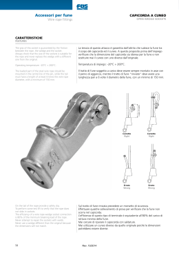
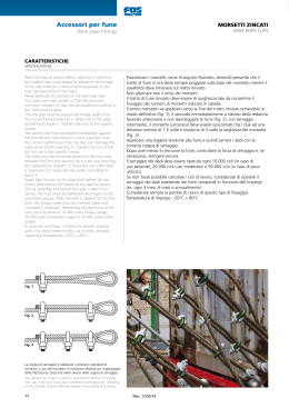
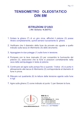
EUROPE DIVISION of Redaelli Tecna S.p.A.
Manuale per uso corretto, manutenzione e controllo accessori
Europe Division Redaelli Tecna S.p.A.
Ed.05.2011 - Rev.2
Foreword
Premessa
All the accessories shown in this manual are made of top quality
materials and they are supplied with certificates and warranties
as required by Italian law (D.Lgs.17/2010) and Machine Directive
2006/42/EC.
The products can be tested at presence of public and private
institutes such as ENEL, RFI, RINA, Lloyd’s Register, ABS etc.
The Teci “Trefolo Rosso” brand is synonymous of quality and
reliability. It has been a leader on the steel wire ropes and
hoisting accessories for more than 100 years.
Teci has for the customers, a qualified technical assistance and a
stock availability spreaded in 9 branches in Italy.
Teci is equipped with tests laboratory for the execution of
destructive and not destructive tests to certify the quality
according to the Italian and international standards.
I prodotti presentati in questo manuale sono fabbricati con
materiali di altissima qualità e vengono forniti corredati da tutte
le certificazioni e garanzie previste dalle disposizioni italiane
(D.Lgs. 17/2010 ) e dalla Direttiva Macchine 2006/42/CE.
Possono essere sottoposti a controlli e omologazioni da parte di
enti pubblici e privati quali ENEL, RFI, RINA, Lloyd’s Register,
ABS, ecc.
Il marchio Teci “Trefolo Rosso” è sinonimo di qualità e garanzia.
Da oltre 100 anni è conosciuto e apprezzato sul mercato delle
funi di acciaio e degli accessori per il sollevamento.
Teci mette a disposizione del cliente un’assistenza tecnica
qualificata e una disponibilità di magazzino distribuita su 9 filiali
in tutta Italia.
Dispone di un laboratorio di controllo interno per l’esecuzione di
prove distruttive e non distruttive a garanzia della qualità e in
conformità alle norme italiane ed estere.
Il Sistema Qualità Teci è certificato in conformità alle Norme ISO 9001:2008
Teci’s quality system is ISO 9001:2008 certified
Europe Division Redaelli Tecna S.p.A.
Ed.05.2011 - Rev.2
2
MONTAGGIO MANUTENZIONE CONTROLLO
APPLICATIONS HANDLING MAINTENANCE
CAMPANELLE / MASTER LINK
CAPICORDA – TERMINALI PER FUNE / SOCKETS – END FITTINGS FOR CABLES
MORSETTI A CAVALLOTTO / WIRE ROPE CLIPS
TENDITORI / TURNBUCKLE
GRILLI / SHACKLE
GANCI / HOOKS
CAPICORDA AUTOBLOCCANTI / OPEN WEDGE SOCKETS
Europe Division Redaelli Tecna S.p.A.
Ed.05.2011 - Rev.2
3
CAMPANELLE / MASTER LINK
Information for safe use and maintenance
The following information aims to give advice in order to
have safe and proper use of lifting equipment
It is important that this information is known to the user,
in accordance with the Machinery Directive 2006-42-CE this
information must be delivered to the customer
Design
Master links are used for 1, 2, 3 and 4-leg
Master links can be supplied with or without a flat part for
easy connection of the master link in the sling;
All master links are suitable for lifting purposes, with a
safety factor of four times the working load limit.
Each master link carries the manufacturer’s
symbol, the steel grade and the CE conformity code
stamped in the body.
Finish
All master links are painted
Instructions for use
Master links should be inspected before use to ensure that:
Master links are free from nicks, gouges and cracks;
Master links, assemblies may not be heat treated as this
may affect their Working Load Limit.
Informazioni per la sicurezza e la manutenzione
Le informazioni seguenti si propongono di dare consigli al
fine di avere l'uso corretto e sicuro di mezzi di
sollevamento
E ' importante che queste informazioni siano conosciute
dall'utente ,in accordo alla Direttiva Macchine 2006-42-CE,
la quale prevede che debbano essere fornite al cliente dal
costruttore
Design
Master links are used for 1, 2, 3 and 4-leg slings Master
links can be supplied with or without a flat part for easy
connection of the master link in the sling;
All master links are suitable for lifting purposes, with a
safety factor of four times the working load limit.
Each master link carries the manufacturer’s symbol, the
steel grade and the CE conformity code stamped in the
body.
Finish
All master links are painted
Istruzioni per l’uso
Le campanelle dovrebbero essere
ispezionate prima
dell’uso per assicurare che le campanelle siano libere da
gole cricche,intagli
Le campanelle assemblate non
possono essere trattate in quanto si potrebbe ridurre il
Carico di utilizzo
Europe Division Redaelli Tecna S.p.A.
Ed.05.2011 - Rev.2
4
CAMPANELLE / MASTER LINK
Istruzioni per l’uso
Instructions for use
These Master links must be inspected
regularly, paying attention to:
- Wear the masterl link when the rod support
- Roundness, distortion of
Do not weld repair and connection to other
products
Check before you use the bell of the real
meaning and analyze the system of lifting the
load to be lifted
Non Usare:Campanelle ovalizzate
e danneggiate
Do not use: Master link ovalized
and damaged
Recording of examinations, maintenance and
repairs
For each master link service connected into
sling in the registry will be reported other
than the date of commissioning, the working
load, the type of sling and traceability.
Register with the manufacturer certificate is
required and shall be updated and signed by
the competent person carrying out the check
and are always
available to the inspecting authority
Non Usare:Campanella con
grave usura
Do not use: Master link
with heavy wear
Europe Division Redaelli Tecna S.p.A.
Ed.05.2011 - Rev.2
Queste campanelle devono essere ispezionate
regolarmente ponendo attenzione a:
- usura della campanella della sede di
appoggio del tirante
- Ovalizzazione ,deformazioni de
-non eseguire saldature di riparazione e di
connessione ad altri manufatti
-controllare prima di usare la campanella
l’effettiva portata ed analizzare il sistema di
sollevamento con il carico da sollevare
Registrazione di esami, manutenzione e
riparazioni
Per ciascuna campanella collegata ad un
imbraco in servizio nell’apposito Registro
dovrà essere riportato oltre la data di messa in
servizio,il carico di lavoro, il tipo di tirante e
la rintracciabilità .
Il Registro con allegato il certificato del
produttore deve essere aggiornato e firmato
dalla persona competente che esegue il
controllo e sempre a disposizione dell’autorità
preposta al controllo
5
CAMPANELLE / MASTER LINK
Maintenance
The components such as cracked. hooks, visibly deformed or bent,
severely corroded or any other deposits that can not be eliminated,
should be discarded and replaced.
Minor damage such as cracks and notches can be removed by careful
grinding or filing.
The surface should be rounded to the material adjacent gradually
without abrupt changes of section.
Manutenzione
I componenti incrinati es. ganci, visibilmente deformati o piegati,
gravemente corrosi o che presentino depositi che non possono
essere eliminati, dovrebbero essere scartati e sostituiti.
Danni di entità minore, quali cricche ed intagli possono essere
eliminati mediante attenta rettifica o limatura.
La superficie dovrebbe essere raggiata gradualmente sul materiale
adiacente senza bruschi cambiamenti di sezione.
Complete removal of the damage should not reduce the thickness of
the section at that point to a lower value of the minimum size
specified by the manufacturer or by more than 15% of the nominal
diameter
La rimozione completa del danno non dovrebbe ridurre lo spessore
della sezione in tale punto ad un valore minore delle dimensioni
minime specificate dal fabbricante o di oltre il 15% del diametro
nominale
Max permissible deviation:
Diameter reduction.
Measures D-d: max 15%
Internal length
Measures L-l- L1-B-b: max 10%
Any deformation present in the master link cuase the
removal from thge service
Deformazioni massime ammesse
Riduzione diametrale
Quote D-d: max 15%
Allungamento lunghezza interna:
quote L-l- 1-B-b: max 10%
Qualsiasi deformazione presente sulla campanella ne
comporta la rimozione dal servizio
Europe Division Redaelli Tecna S.p.A.
Ed.05.2011 - Rev.2
6
CAPICORDA – TERMINALI PER FUNE / SOCKETS – END FITTINGS FOR CABLES
Information for safe use and maintenance
The following information aims to give advice in order to have safe
and proper use of lifting equipment
It is important that this information is known to the user, in
accordance with the Machinery Directive 2006-42-CE this information
must be delivered to the customer
Informazioni per la sicurezza e la manutenzione
Le informazioni seguenti si propongono di dare consigli al fine di
avere l'uso corretto e sicuro di mezzi di sollevamento.
E ' importante che queste informazioni siano conosciute dall'utente,
in accordo alla Direttiva Macchine 2006-42-CE, la quale prevede che
debbano essere fornite al cliente dal costruttore
With reference to the figures at the end page of this document the
sockets there are sample of socktets (end-fittings) used in guy ropes:
They are divided in:
1) Swaged socket
They are mainly classified in Open Fork or Jaw, Closed or eye and
stud or threaded.
According to the ropes to which must be swaged they can be
delivered ungalvanised, hot dip galvanised or electrolytic galvanised
(sockets with thread), in carbon steel or stainless steel.
The swaging application of the socket on the rope must be done by
cold deformation of the socket over the cable This operation is
effected with the use of special dies and special hydraulic motor
press with high force power
The application of the end-fittings through the swaging operation ,
guarantees an efficiency rating equal to 90% of the cable nominal
MBF
Con riferimento alle figure riportate in ultima pagina alcuni esempi
di capicorda (terminali ) utilizzati in stralli fissi :
Essi si dividono in:
1) Pressati:
Si distinguono principalmente in aperti, chiusi e filettati.
In funzione delle funi cui vanno accoppiati, possono essere forniti in
acciaio lucido, zincati a caldo o elettroliticamente (filettati) in
acciaio al carbonio o inox.
L’applicazione del capocorda alla fune avviene mediante
deformazione a freddo del manicotto del capocorda sulla fune
(pressatura).
L’operazione è effettuata con l’utilizzo d'appositi stampi e presse di
notevole capacità.
L’applicazione dei terminali mediante pressatura garantisce un grado
d'efficienza dell’attacco pari a 90% della forza di rottura nominale
della fune
Spelter sockets: Cable sealing after installation:
Capicorda a testa fusa:Sigillatura fune dopo montaggio
Europe Division Redaelli Tecna S.p.A.
Ed.05.2011 - Rev.2
7
CAPICORDA – TERMINALI PER FUNE / SOCKETS – END FITTINGS FOR CABLES
2) Spelter sockets:
They can be delivered in Open or Fork type, Closed type in carbon
steel forged or casting.
The application of these sockets (socketing) is made by pure melt
zinc, special alloy low-melt and resins for structural application
according to special procedures and modality, guaranteeing an
efficiency rating equal to 100% of the Min. Breaking Force of the
rope.
The sockets can be delivered also galvanised or in stainless steel: in
conformity of the ropes to which must be joined.
After installation when the stay cable are putting under force, the
cone inside the basket could settle down. If it is necessary the area
where the rope enters the socket ( basket nose) shall be clean by
brush and sealed
USE-MAINTENANCE-INSPECTION
All the examinations and controls must have effected from
competent person that is able of detecting and to evaluate the
defects that they are found.
Control's frequency for lifting slings in service has to be done of
three months (max 6 months in function of the use and integrity of
the sling).
For stay cables the frequency control must be conforming to designer
indications.
The Inspection register with manufacturer certificate enclosed must
be adjourns and always to disposition of the Inspectorate authority
to the control. Rope examination will be effected, as brought in the
chapter "Wire rope sling " Examination on the end-fittings must be
made visually, dimensionally and NDT testing to identify the
damages, cracks and the deterioration that can reduce safety
2) Capicorda a tesa fusa
Possono essere del tipo aperto, chiuso in acciaio al carbonio
stampati e/o fusi.
L’applicazione di questi capicorda avviene per mezzo di zinco fuso,
leghe basso fondenti e resine per impieghi strutturali, secondo
apposite procedure e modalità, garantendo un grado di efficienza
pari al 100% del carico di rottura della fune
I capicorda possono essere forniti anche zincati o in acciaio inox, in
funzione dell’impiego e delle funi cui vanno accoppiati.
Dopo installazione quando il tirante viene messo sotto tiro, il cono
delle fune dentro il capocorda potrebbe assestarsi. Se necessario la
zona di uscita fune dal capocorda deve essere pulita con spazzola e
poi sigillata.
USO-MANUTENZIONE-CONTROLLO
Tutti gli esami e controlli devono essere effettuati da personale
competente, che sia in grado di rilevare e valutare i difetti che
vengono riscontrati.
La frequenza di controllo per le brache in servizio deve essere di tre
mesi
(max 6 mesi in funzione dell’uso e dell’integrità del tirante).
Per le strallature fisse la frequenza è stabilita dal progettista.
Il registro delle Ispezioni con allegato i certificati del produttore
deve essere aggiornato e sempre a disposizione dell’autorità
preposta al controllo. L’esame della fune dovrà essere effettuato,
come riportato nel capitolo “Brache in fune”.
L’esame sui terminali metallici dovrà essere fatto visivamente,
dimensionalmente con controlli NDT al fine di identificare i danni e i
deterioramenti che possono pregiudicarne la sicurezza
Europe Division Redaelli Tecna S.p.A.
Ed.05.2011 - Rev.2
8
CAPICORDA – TERMINALI PER FUNE / SOCKETS – END FITTINGS FOR CABLES
- Broken wires breaking in the point of attack, or in its
proximity, state that point of attack has been subject to many
stress. This stress might be caused by an incorrect installation
handling of the end-fittings (es. out alignment from force axe). In
this case is necessary to find what combined to bring about the
deterioration.
- damages came from socket heating on the socket are clearly
visible by seeing a colour variation of the material and noting a
change of the protective layer (galvanisation). These alteration
might be caused by the electric arc or by nearness flames that
cause the heating of the socket. These damages are dangerous
as the end fitting and consequently the sling reduce significantly
the breaking force.
- Magnetic particle examination or ultrasonic testing on the
end-fittings must be carried out in case of damages. Made NDT
examinations to verify the presence of cracks their entity.
Common defects on the sockets are:
*distortions and/or opening of the forks of the sockets
*distortions and wear of the retaining links and/or of pin closing
(e.g. split pin)
*abrasion, wear, break and crack covering the body of the
socket.
The end-fittings with deformations e/o critical abrasions are
dangerous and they must have immediately replaced. In presence
of surface cracks the sockets must be immediately replaced,
except, prior manufacturer consultation, notified damages might
be removed.
- Corrosion control: it is no possible to avoid the negative
effects of the corrosion, but it is possible and needed to identify
the corrosion status on the main parts of the end-fitting,
Welding: welding on the end-fitting on the sockets are never
allowed, either to repair incisions/anomalies, either to connect
other link accessories.
- Rottura dei fili nel punto di attacco o in prossimità di questo
indicano che le tensioni qui esercitate sono elevate e possono
essere state provocate da un montaggio in opera non corretto dei
terminali (es. fuori allineamento con asse di tiro). In questo caso
è necessario cercare la causa che ha prodotto il deterioramento.
- Danni derivati da riscaldamento sul capocorda si identificano
con variazioni del colore del materiale e modifica dello strato
protettivo (zincatura). Possono essere causati dall’arco elettrico
e/o da riscaldamenti provocati da fiamme poste nelle vicinanze.
Questi danni sono dannosi in quanto il terminale, e di
conseguenza il tirante, riducono notevolmente il carico di
rottura.
- Esame magnetoscopico e/o ultrasonoro sui terminali da
eseguire in caso di danni ai terminali deve essere fatto. Eseguire
esami NDT per accertare la presenza di cricche e la loro entità.
I difetti comunemente riscontrabili sui capicorda sono:
• distorsioni e/o apertura delle forcelle dei capicorda
• distorsioni e usura delle connessioni di ritenuta e/o chiusura
dei perni (es. copiglie)
• abrasioni, usura, rotture e cricche sul corpo del capocorda. II
capicorda con deformazioni e/o abrasioni critiche pregiudicano
la tenuta e devono essere immediatamente sostituiti. In presenza
di cricche superficiali i terminali devono essere sostituiti, almeno
che, previa consultazione del fabbricante, tali difetti possano
essere rimossi.
- Controllo della corrosione: non è possibile evitare gli effetti
negativi della corrosione, ma è possibile e necessario verificarne
l’entità sulle parti principali del capocorda (es. perno, copiglia,
filetto …).
- Saldature: non sono ammesse saldature sui capicorda, sia
quelle eseguite per riparare incisioni/anomalie, sia quelle
eseguite per attaccare altri accessori.
Europe Division Redaelli Tecna S.p.A.
Ed.05.2011 - Rev.2
9
CAPICORDA – TERMINALI PER FUNE / SOCKETS – END FITTINGS FOR CABLES
Coated surface inspection :
the condition and the zinc life coating shall depend on environmental
conditions.
- in order to preserve the integrity during the time a painting must be carried
out
- galvanic corrosion: to avoid to couple between them materials with different
electro chemical potential
2) The preservation of resistance and breaking force of the wire ropes, of the
end-fittings and accessories are subjected to a regular inspection and
maintenance.
Followings further specifications.
3) Inspection and maintenance:
The following information have to be considered as not exhaustive and
integrative to that established by designer
3.1 Inspections
First visual inspection after the erection. Visual inspection (yearly inspection)
to put in evidence wire rope sliding , corrosion (rusty) and surface aspect of the
rope and sockets.
-approached inspection on the whole elements specially the end-fittings, areas
with clamps pins, sliding or adjustments of end-fittings deformations integrity
of the protections( galvanisation)
Record Inspection
The controls recording effected by competent person must be signed on
Inspection Register with the date of the control On this register must be
registered the controls, the defects found and the corrective actions
performed.
End- Fitting types: Threaded Swaged socket ( Stud end-fitting)
Ispezione della superficie zincata
. la condizione e la durata dello strato di zinco dipenderà dalle condizioni
ambientali.
- verniciatura deve essere eseguita per preservare l'integrità durante il tempo
- corrosione galvanica: evitare di accoppiare tra loro materiali con diverso
potenziale elettrochimico
2) la conservazione di resistenza e carico di rottura della fune, dei terminali e
degli accessori è mantenuta solo se sono sottoposti ad una regolare ispezione e
manutenzione. di seguito alcune ulteriori informazioni:
3) ispezione e manutenzione:
Le informazioni seguenti devono essere considerate come non esaurienti ed
integrative a quello stabilito dal progettista della strallatura.
3.1 Ispezioni
Prima ispezione subito dopo il montaggio. Esame visivo (ispezione annuale) per
mettere in evidenza slittamenti della fune, corrosione (ruggine) ed aspetto
della superficie della fune e dei capicorda
Ispezione ravvicinata sugli elementi interi specialmente i terminali, aree con
morsetti, perni, slittamenti o aggiustamenti di capicorda deformazioni della
integrità del rivestimento protettivo ( zincatura)
Registrazione Ispezioni
Le registrazione dei controlli fatti dalla persona competente devono essere
firmati sul Registro delle Ispezioni riportando la data del controllo Sul registro
devono essere riportati i controlli, i difetti riscontrati e le azioni correttive.
End-Fitting types: OPEN and CLOSED spelter sockets
Open and Closed swaged sockets
Conical spelter socket with threaded bar
Open spelter socket and Bridge socket with bar for regulation and tensioning (turnbuckle)
B
A
Cs
Dt
Europe Division Redaelli Tecna S.p.A.
Ed.05.2011 - Rev.2
M
10
MORSETTI A CAVALLOTTO / WIRE ROPE CLIPS
Information for safe use and maintenance
The following information aims to give advice in order to have
safe and proper use of lifting equipment
It is important that this information is known to the user, in
accordance with the Machinery Directive 2006-42-CE this
information must be delivered to the customer
WIRE ROPE CLAMPS
They are generally employed in the formation of soft-eye for
anchorage, joining them to thimble that protect the rope against
damages, and in all those situations of emergency where the
socket or the pressed eye are not applicable (for example when
it is no possible to measure and/or in case of unavailability of
fixed reference points.
The wire rope clips cannot be used to create an eye-eye type
connection sling to be employed in lifting activities.
For the assemblage :
- check that the measure of the clamps is right in function of the
rope diameter to which they must be applied
- use the exact number of clamps required as shown in tab.1
- keep in consideration the grade of efficiency factor of the
connection to build as shown in tab.2
- establish (and mark on the rope) the length of the part of rope
to turn back
- not to use the clamps on ropes coated with plastic material
- remember that a wrong assembly (as in fig. 4) decreases of 60%
the efficiency of the complete device (in comparison to the
minimum breaking load of the rope used).
Informazioni per la sicurezza e la manutenzione
Le informazioni seguenti si propongono di dare consigli al fine di
avere l'uso corretto e sicuro di mezzi di sollevamento
E ' importante che queste informazioni siano conosciute
dall'utente ,in accordo alla Direttiva Macchine 2006-42-CE, la
quale prevede che debbano essere fornite al cliente dal
costruttore
MORSETTI A CAVALLOTTO
I morsetti sono impiegati generalmente nella formazione di asole
per l’ancoraggio, accoppiandoli a radance che proteggono la fune
contro danni, ed in tutte quelle situazioni di emergenza dove i
capicorda o le asole pressate non sono applicabili come in
mancanza di misure e/o riferimenti fissi.
I morsetti non possono essere utilizzati per realizzare tiranti
asola - asola da impiegare nel sollevamento.
Per il montaggio:
- controllare che la misura del morsetto impiegato sia corretta in
funzione del diametro della fune alla quale va accoppiato
- controllare il numero di morsetti richiesti vedi tab. 1
- tenere in considerazione il grado di efficienza della connessione
come riportato in tabella 2.
- determinare e contrassegnare la lunghezza del tratto di fune da
rinviare
- non usare i morsetti su funi rivestite di materiale plastico
- ricordare che il montaggio errato (come fig.4) diminuisce
l’efficienza dell’attacco del 60% rispetto al carico di rottura della
fune.
Europe Division Redaelli Tecna S.p.A.
Ed.05.2011 - Rev.2
11
MORSETTI A CAVALLOTTO / WIRE ROPE CLIPS
INSTRUCTIONS FOR THE APPLICATION
The assemblage must be done as shown in fig. 1, 2 and 3 strictly
following these instructions :
- the saddle of the clip must be fixed on the tractive part of the
rope and the arch on the dead part of the rope.
- the clamps must not be fixed in alternate way on the rope (as
in fig.4).
- The rope turned back (dead part) must be long enough to allow
the fixing of the right number of clamps (as indicated in the
tab.1).
-maintain a distance between the clips wider compared with the
width of the clips saddle width (approximately 4 times the wire
rope diameter).
Wire rope clips application
fig.1) The first clamp must be applied at the end of the turn back
line
fig. 2) The second clamp must be put immediately against the
thimble watching out to avoid wire breaks. Fix the saddle on the
tractive branch of the rope and fix the arch on the dead part,
then tighten the nuts: the value of the torque force has to be
inferior to the definitive one.
fig.3) all the other clamps must be fixed among the first one and
the second clamp fairly outdistanced the one by the other with a
minimal distance equal to two times the saddle width.
Apply a light tension on the rope so that the two lines of rope are
equally stretched.
After the first lifting
torque force has to
requested value.
This operation must
doing the opportune
wire rope and clamps
and before the rope is put in service the
be re - checked and heightened to the
be repeated at regular intervals of time
corrective actions in case sliding between
are found.
ISTRUZIONI PER L’APPLICAZIONE
Il montaggio deve essere effettuato come riportato nelle figure
1, 2 e 3 seguendo scrupolosamente le istruzioni di seguito
riportate:
- l’appoggio della sella del morsetto deve essere fissato sul tratto
in tiro della fune ed il cavallotto sul capo rinviato della fune
(capo morto).
- i morsetti non devono essere montati in modo alternato sulla
fune (come in fig. 4).
- il tratto di fune rinviato dovrà essere di una lunghezza
sufficiente a permettere il fissaggio del corretto numero di
morsetti come indicato nella tabella 1.
- mantenere una distanza tra i morsetti maggiore della larghezza
della sella di appoggio dei morsetti: indicativamente circa 4
volte il diametro della fune.
Applicazione morsetti
fig.1) Il primo morsetto va applicato alla fine del tratto rinviato
fig.2) Il secondo deve essere fissato contro la radancia facendo
attenzione affinché non vengano danneggiati i fili della fune.
Appoggiare la sella sul ramo di fune in tiro e posizionare il
cavallotto sul capo morto e stringere i dadi: il valore della coppia
di serraggio deve essere inferiore alla coppia definitiva .
fig.3) Tutti gli altri morsetti devono essere montati tra il primo e
il secondo morsetto equamente distanziati gli uni dagli altri con
interasse minimo uguale al doppio della larghezza sella .
Applicare una leggera tensione sulla fune affinché i due tratti di
fune siano equamente tesi.
Dopo il primo sollevamento e prima che la fune sia messa in
servizio la forza di serraggio, deve essere ricontrollata e portata
alla forza richiesta.
Questa operazione deve essere ripetuta ad intervalli di tempo
regolari registrando e attuando le opportune azioni correttive se
vengono riscontrati slittamenti.
Europe Division Redaelli Tecna S.p.A.
Ed.05.2011 - Rev.2
12
MORSETTI A CAVALLOTTO / WIRE ROPE CLIPS
USE AND MAINTENANCE
USO E MANUTENZIONE
The efficiency of the device depends on the correct number and
positioning of the clamps, which must be fixed with the right
torque force without damaging the surface of the rope. Since a
series of factors can influence the torque force of the clamp it is
necessary to check that the joining nut thread doesn't present
seizures and or rust in order to allow the correct torque force of
the nut and without the coefficient of friction between saddle
of the clamp and nut results changed (influencing the value of
the torque force).
It is recommended not to use soft eyes produces with clamps for
lifting activities in:
- elements of connection in crane of steel mills and rolling mills
- terminal of ropes working under pulsating loads
- elevators for mines
Never use clamps to link together pieces of rope.
L’efficienza dell’asola dipende dal corretto numero e
posizionamento dei morsetti impiegati, i quali devono essere
serrati alla giusta coppia senza incidere i fili della fune. Poiché
una serie di fattori può influenzare il serraggio del morsetto
bisogna controllare che l’accoppiamento dado - filetto non
presenti grippaggi e/o arrugginimenti onde permettere il
corretto serraggio dei dadi senza diminuire il coefficiente di
attrito tra sella del morsetto e dado (influenzando il valore della
coppia di serraggio) .
Si raccomanda di non usare asole formate con morsetti per il
sollevamento in:
- elementi di connessione in gru di acciaierie e laminatoi
- terminali di funi che lavorano a carichi pulsanti
- elevatori per miniere
- mai usare morsetti a cavallotto per unire tra loro due spezzoni
di fune.
Europe Division Redaelli Tecna S.p.A.
Ed.05.2011 - Rev.2
13
MORSETTI A CAVALLOTTO / WIRE ROPE CLIPS
Table-1
Clamp
size
For wire rope
Dia.
Dia.
inch
mm
Clamp
Min.
Nr.
A
mm
D i m e n s i o ns
B
C
D
mm
mm
mm
E
mm
S
mm
Approx
Turn back
length
Torque
Force
in N*m
3
5
6,5
8
1/8
3/16
¼
5/16
3-4
4,1-5
5,1-6,5
6,6-8,5
3
3
3
5
16
19
23
32
18
24
27
31
9
13
15
17
M4
M5
M6
M6
12
13
15
19
10
15
16
18
80
110
210
240
1,25
2,46
4,24
4,24
10
11
13
14
3/8
7/16
½
9/16
8,6-10
10,1-11
11,1-13
13,1-14
5
5
5
5
34
36
45
47
37
41
44
47
20
22
25
27
M8
M8
M 10
M 10
22
22
33
33
21
24
26
27
240
260
300
300
10,20
10,20
20,11
20,11
16
18
20
22
5/8
11/16
¾
7/8
14,1-16
16,1-18
18,1-20
20,1-22
5
5
5
7
53
63
65
73
51
56
62
65
29
34
34
39
M 10
M 12
M 12
M 12
33
44
44
52
28
32
33
35
335
380
540
600
20,11
34,43
34,43
34,43
26
30
34
1
1.1/8
1.1/4
22,1-26
26,1-30
30,1-34
7
8
8
81
96
104
72
78
88
42
49
53
M 14
M 14
M 16
50
50
55
40
43
48
700
990
1155
54,77
54,77
85,14
40
1.1/2
34,1-40
8
124
98
59
M 16
60
54
1320
85,14
Europe Division Redaelli Tecna S.p.A.
Ed.05.2011 - Rev.2
14
TENDITORI / TURNBUCKLE
Information for safe use and maintenance
The following information aims to give advice in order to have
safe and proper use of lifting equipment
It is important that this information is known to the user, in
accordance with the Machinery Directive 2006-42-CE this
information must be delivered to the customer
TURNBUCKLE
They are used for tensioning and they can be furnished in
different configurations as:
eye-eye;
eye-fork;
fork-fork;
stud-fork
Swaged Turnbuckle type Stud-Fork
They are normally delivered with electrolytic galvanisation (with
threaded parts),
The swaging application on the rope must be done by cold
deformation of the socket over the cable This operation is
effected with the use of special dies and swaged with special
hydraulic motor press with high force power
The application of the end-fittings through the swaging operation
, guarantees an efficiency rating equal to 90% of the cable MBF
The turnbuckles unified by the same specification have the
varied parts, to parity of working load, interchangeable between
them.
The central part (body) of connection between the different
terminals is generally, if not otherwise specified , delivered as
open type.
Instructions for the use
Turnbuckle are employees mainly
in fixed structures for
tensioning the cables, turnbuckle must not used for lifting. The
turnbuckles aren't designed to efforts not aligned along the force
axis.
The rotation of the central body makes to approach the terminals
producing an axial force. Pay attention: do not rotate the rope
during the body rotation
Informazioni per la sicurezza e la manutenzione
Le informazioni seguenti si propongono di dare consigli al fine di avere
l'uso corretto e sicuro di mezzi di sollevamento.
E ' importante che queste informazioni siano conosciute dall'utente ,in
accordo alla Direttiva Macchine 2006-42-CE, la quale prevede che
debbano essere fornite al cliente dal costruttore
TENDITORI
Servono per tensionare e possono essere forniti in diverse
configurazioni come:
- occhio - occhio
- occhio - forcella
- forcella - forcella
- asta- forcella
Tenditori Pressati tipo asta - forcella
Sono normalmente forniti con superficie zincata elettroliticamente
(filettati),
L’applicazione avviene mediante deformazione a freddo del manicotto
del capocorda sulla fune (pressatura). L’operazione è effettuata con
l’utilizzo d'appositi stampi e presse di notevole capacità.
L’applicazione dei terminali mediante pressatura garantisce un grado
d'efficienza dell’attacco pari a 90% del carico rottura nominale della
fune
I tenditori unificati dalla stessa norma hanno le varie parti, a parità di
portata, intercambiabili tra loro.
La parte centrale di collegamento (canaula) tra vari terminali è
generalmente, se non diversamente specificato, fornita di tipo aperto.
Istruzioni per l’uso
I tenditori vengono principalmente impiegati in strutture fisse per
tensionare i cavi. I tenditori non devono essere usati per sollevare. I
tenditori sono dimensionati per sopportare forze i non allineate lungo
l’asse di tiro.
La rotazione del corpo centrale fa avvicinare i terminali generando un
tiro assiale.
Far attenzione: non far ruotare la fune durante la rotazione della
canaula
Europe Division Redaelli Tecna S.p.A.
Ed.05.2011 - Rev.2
15
TENDITORI / TURNBUCKLE
MAINTENANCE and CONTROL
The turnbuckle must be regularly inspected at intervals of time
established by the structural designer
Particular attention must be done during the tension: do not
overcome the working load in order to avoid
permanent
deformations.
Pulsating solicitations must be not applied on turnbuckle In case
of deformations immediately suspend the assembling
Damaged parts of the turnbuckle must be immediately be
replaced.
The working load must be applies only through force and not
overloaded with other tools. Folds and side loads must not be
applied to the turnbuckle because it is not designed for this
function.
The Turnbuckles must be inspected before the use to assure that:
- the body and the terminals are not distorted and damaged
- the thread parts must be entire and not damaged
- the body and the terminals are not damaged and free from
incisions and crack
It is necessary in case of damages to the end-fittings to
perform examinations by Non Destructive Test to verify the
presence of cracks and their entity
- All terminals must be correctly inserted in the body and that
the threaded is screwed in the body for a length equal to its
diameter.
The threaded parts are slightly protected against the oxidation to
get a good mechanical joining among the thread
When the turnbuckle are put in final position the protection
against the oxidation must be done
Don't
heat and to perform welding of reparation on the
turnbuckle
MANUTENZIONE E CONTROLLO
I tenditori devono essere regolarmente ispezionati ad intervalli
di tempo stabiliti dal progettista dell'opera
Particolare attenzione deve essere posta durante il
tensionamento per non superare il carico di lavoro per evitare
deformazioni permanenti.
In nessun modo devono essere applicate sollecitazioni pulsanti. In
caso di deformazioni sospendere immediatamente il montaggio
Parti danneggiate devono essere immediatamente sostituite.
Il carico di lavoro deve essere applicato solo tramite tiro e non
sovraccaricato con altri mezzi. Pieghe e carichi laterali non
devono essere applicati al tenditore in quanto non dimensionato
per questa funzione.
I tenditori devono essere ispezionati prima dell’uso per
assicurarsi che:
- il corpo e i terminali non siano distorti e danneggiati
- le parti filettate siano ingrassate
- il fletto sia integro e in buono stato
- il corpo e i terminali non siano danneggiati e liberi da incisioni
e cricche
-in caso di danni ai terminali è opportuno eseguire esami Non
Distruttivi per accertare la presenza di cricche ed eventualmente
la loro entità.
-i terminali siano correttamente inseriti nel corpo e che il filetto
sia in presa per una lunghezza minima pari al suo diametro.
Le parti filettate sono leggermente protette contro l’ossidazione
per ottenere un buon accoppiamento meccanico tra le filettature
Quando il tenditore sarà messo in posizione finale provvedere
alla protezione contro l’ossidazione
Non scaldare ed eseguire saldature di riparazione sul tenditore
Europe Division Redaelli Tecna S.p.A.
Ed.05.2011 - Rev.2
16
TENDITORI / TURNBUCKLE
Coated surface inspection :
the condition and the zinc life coating shall depend on
environmental conditions.
- in order to preserve the integrity during the time a painting
must be carried out
galvanic corrosion: avoid coupling between them materials with
different electrochemical potential
The preservation of resistance and breaking force of the wire
ropes, of the end-fittings and accessories are subjected to a
regular inspection and maintenance.
Followings further specifications.
Inspection and maintenance:
The following information have to be considered as not
exhaustive and integrative to that established by structural
designer
a) Inspections
First visual inspection after the assembly Visual inspection (yearly
inspection) to put in evidence sliding clamp breaks, corrosion
(rusty) and surface aspect of the rope and turnbuckle
b) approached inspection on the whole elements specially the
end-fittings, areas with clamps pins, sliding or adjustments of
end-fittings deformations integrity of the protections
(galvanisation)
Record Inspection
The controls recording must be effected by competent person.
The controls brought on special Register of the Inspections with
the date of the control and the signature of whom has performed
the controls.
On the register must be registered the defects found if there are
and the corrective actions performed
Ispezione della superficie zincata
la condizione e la durata dello strato di zinco dipenderà dalle
condizioni ambientali.
La verniciatura deve essere eseguita per preservare l'integrità
durante il tempo
corrosione galvanica: evitare di accoppiare tra loro materiali con
diverso potenziale elettrochimico
La conservazione di resistenza e carico di rottura della fune, dei
terminali e degli accessori è mantenuta solo se sono sottoposti
ad una regolare ispezione e manutenzione.
Di seguito alcune ulteriori informazioni:
ispezione e manutenzione:
Le informazioni seguenti devono essere considerate come non
esaurienti ed integrative a quello stabilito dal progettista della
struttura
a) Ispezioni
Prima ispezione subito dopo il montaggio. Esame visivo
(ispezione annuale) per mettere in evidenza slittamenti dei
morsetti, corrosione (ruggine) ed aspetto della superficie della
fune e del tenditore.
b) Ispezione ravvicinata sugli elementi interi specialmente i
terminali, aree con morsetti, perni, slittamenti o aggiustamenti
di capicorda deformazioni della integrità del rivestimento
protettivo ( zincatura)
Registrazione Ispezioni
Le registrazione dei controlli effettuati da persona competente
devono essere riportati su apposito Registro delle Ispezioni
riportando la data del controllo e la firma di chi ha eseguito il
controllo.
Sul registro devono essere riportati
i controlli, i difetti
riscontrati e le azioni correttive eseguite.
Europe Division Redaelli Tecna S.p.A.
Ed.05.2011 - Rev.2
17
TENDITORI / TURNBUCKLE
Turnbuckle type: Fork –Fork
Tenditore tipo: Forcella-Forcella
Turnbuckle type: Eye –Eye
Tenditore tipo. Occhio-Occhio
Turnbuckle type: Fork –Eye
Tenditore tipo Forcella-Occhio
Turnbuckle type: Stud–Fork
Tenditore tipo: Asta-Forcella
Europe Division Redaelli Tecna S.p.A.
Ed.05.2011 - Rev.2
18
GRILLI / SHACKLE
Information for safe use and maintenance
The following information aims to give advice in order to have
safe and proper use of lifting equipment
It is important that this information is known to the user, in
accordance with the Machinery Directive 2006-42-CE this
information must be delivered to the customer
Side loads
Side loads on shackles should be avoided as them are not
designed for this purpose.
If side loads cannot be avoided, reduction factors must be taken
into account in relationship with the work angle:
0°
Max Working Load = 100% of original Working Load Limit
Informazioni per la sicurezza e la manutenzione
Le informazioni seguenti si propongono di dare consigli al fine di
avere l'uso corretto e sicuro di mezzi di sollevamento
E ' importante che queste informazioni siano conosciute
dall'utente ,in accordo alla Direttiva Macchine 2006-42-CE, la
quale prevede che debbano essere fornite al cliente dal
costruttore
Carichi laterali
I carichi laterali dovrebbero essere evitati poiché i grilli non
sono progettati a questo fine.
Se non possono essere evitatati devono essere considerati dei
fattori di riduzione in relazione al carico di lavoro in uso:
45° Max Working Load = 70% of original Working Load Limit
0°
Carico di Lavoro Massimo = 100% del carico di lavoro
massimo
90 ° Max Working Load = 50% of original Working Load Limit
45° Carico di Lavoro Massimo = 70% del carico di lavoro massimo
When shackles are used in connection with multi-leg slings, due
consideration should be given to the effect resulting: increasing
the work angles the tensioning on the ropes also increases and
then obviously on the shackles linked to the ropes.
90° Carico di Lavoro Massimo = 50% del carico di lavoro massimo
Quando il grillo viene usato con imbrachi a più braccia bisogna
tenere in considerazione gli effetti risultanti: all’aumentare
dell’angolo di lavoro aumenta il tiro nei tiranti
e
conseguentemente sui grilli collegati ai tiranti.
Europe Division Redaelli Tecna S.p.A.
Ed.05.2011 - Rev.2
19
GRILLI / SHACKLE
Right and Wrong use of shackles
Uso proprio ed improprio dei grilli
Corretto
Right
Errato
Wrong
3 - Corretto - Right
4 - Errato - Wrong
Europe Division Redaelli Tecna S.p.A.
Ed.05.2011 - Rev.2
20
GRILLI / SHACKLE
When a shackle is used to connect two slings to the hook of a
lifting device, a bow type shackle must be used, with the slings in
the shackle body and the hook engaged with the shackle pin.
The angle between the slings should not exceed 120°.
To avoid eccentric loading of the shackle a loose spacer may be
used on either end of the shackle pin.
Do not reduce the width between the shackle jaws by welding
washers or spacers to the inside faces of the eyes or by closing the
jaws, as this will affect the properties of the shackle.
Quando un grillo è utilizzato per collegare due imbrachi al gancio di
sollevamento, un grillo ad omega deve essere collegato, con il
tirante nel corpo del grillo ed il gancio collegato con il perno del
grillo. L'angolo fra gli imbrachi non dovrebbe superare 120°.
Per evitare carichi eccentrici sul grillo dovrebbe essere usato un
distanziatore libero su entrambe le estremità del perno del grillo
Non ridurre la larghezza fra le staffe del grillo saldando rondelle o
distanziatori tra le facce interne delle staffe o chiudendo le forcelle,
poiché questo ridurrà le proprietà del grillo .
RIGHT -WRONG method
When a shackle is used to secure the top block of a set of wire
rope blocks the load on this shackle is increased by the value of
the hoisting effect.
Uso Corretto - Errato
Quando un grillo è utilizzato per fissare un bozzello di una serie di
pulegge di rinvio di funi metallica il carico sul grillo è aumentato dal
valore del bozzello di sollevamento.
Evitare le applicazioni dovute al movimento ( es. del carico o
della fune) il perno del grillo può ruotare svitandosi
Avoid applications where due to movement (e.g. of the load or the
rope) the shackle pin can rotate and possibly be unscrewed.
If such an application Is necessary or when the shackle is to be
left in place for a prolonged period or where maximum pin security
is required, use a shackle with a safety bolt, nut and split cotter
pin
Shackles should not be immersed in acidic solutions or exposed to
acid fumes or other chemicals that are potentially harmful for the
shackle.
Please be aware that these types of chemicals are used in certain
production processes.
Point loading: Most of the item the load bearing component that is
in connection with a shackle is of a rounded shape.
Se tale applicazione è necessaria o quando il grillo deve essere
lasciato in opera per un periodo prolungato o dove è richiesta la
massima sicurezza del perno,usare grillo con perno dado e
copiglia.
I grilli non devono essere immersi in soluzioni acide o vapori acidi o
altri prodotti chimici che sono potenzialmente nocivi per grillo.
Informarsi sui tipi di prodotti chimici sono utilizzati nei processi di
produzione
Punti di carico: La maggior parte dei punti che vengono collegati al
grillo hanno forma arrotondata.
Europe Division Redaelli Tecna S.p.A.
Ed.05.2011 - Rev.2
21
GRILLI / SHACKLE
Point loading of shackles is allowed but the minimum diameter of
a rounded component should be equal or bigger than the bow
size of the shackle being used.
Punti di collegamento dei grilli è permesso con componenti
arrotondati ma il diametro minimo dovrebbe essere uguale o più
grande dell'arco della Forcella (omega) del grillo
Bigger diameters and or flat parts (at shackle pin side) to
increase contact area can be beneficial
Diametri più grandi e o parti piane (appoggio del perno ) per
aumentare la zona di contatto dovrebbero essere adottate
Sharp edges should be avoided.
Gli spigoli vivi devono essere evitati.
Temperature
If extreme temperature situations are applicable, the following
load reduction must be taken into account:
Temperatura
Se estreme situazioni
di temperatura sono applicabili, le
seguenti riduzioni
di carico devono essere prese in
considerazione:
Reduction from the working Load Limit for
temperatures
Temperature
New Working Load limit
up to 200·°C
100% of original Working Load Limit
200 - 300 °C
90% of original Working Load Limit
300- 400 °C
75% of original Working Load limit
> 400 °C
not allowed
elevated
Riduzione del carico di lavoro ultimo per elevate temperature
Temperatura
Nuovo WLL
fino a 200 °C
100%
200 –300 °C
90% del WLL
300°400 °C
75% del WLL
>400 °C
non permessa
The rating of shackles to EN 13889 assumes the absence of
exceptionally hazardous conditions.
Exceptionally hazardous conditions include offshore activities,
the lifting of persons and the lifting of potentially dangerous
loads such as molten metals, corrosive materials or fissile
materials.
La conformità del grillo ad EN 13889 presuppone l'assenza di
circostanze eccezionalmente pericolose.
Particolari condizioni pericolose includono attività in mare
aperto,il sollevamento di persone e la sospensione di carichi
potenzialmente pericolosi quali metalli fusi, materiali corrosivi o
materiali fissili.
In such cases a competent person should assess the degree of
hazard and the safe working load should be reduced accordingly
In tali casi una persona competente dovrebbe valutare il grado
di rischio ed il carico sicuro applicabile riducendo di conseguenza
il WLL
Europe Division Redaelli Tecna S.p.A.
Ed.05.2011 - Rev.2
22
GRILLI / SHACKLE
Inspection
It is required that the shackles are regularly inspected and that
the inspection should lake place in accordance with the safety
standards given in the country of use.
This is required because the products in use may be affected by
wear, misuse, overloading etc. with a consequence of
deformation and alteration of the material structure.
Inspection should take place al least every six months and even
more frequently when the shackles are used in severe operating
conditions.
Proof load testing
Il is required that the shackles are regularly proof load tested
and that the testing should take place in accor-dance with the
safety standards given in the country of use.
This is required because the products in use may be affected by
wear, misuse, overloading etc. with a consequence of
deformation and alteration of the material structure. Proof load
testing should take place at least every 4 years and more
frequently when the shackles are used in severe operating
conditions.
Ispezione e Controllo
Il grillo deve essere ispezionato regolarmente e l’ispezione deve
essere fatta in accordo agli standard di sicurezza dati nel paese
in uso.
Questo è richiesto perché i prodotti in uso possono essere
danneggiati da usura, uso improprio, sovraccaricanti ecc. con una
conseguente deformazione ed alterazione della struttura
materiale. L’Ispezione dovrebbe essere fatta almeno ogni sei
mesi e più frequentemente quando il grillo è utilizzato in severe
condizioni operative
Prova di carico
Se è richiesto che i grilli siano singolarmente collaudati mediante
prova di carico questa deve essere fatta in conformità agli
standard di sicurezza dati nel paese di uso.
Questo è richiesto perché i prodotti in uso possono essere
danneggiati da usura, uso improprio, sovraccaricanti ecc. con una
conseguente deformazione ed alterazione della struttura
materiale. Prova di carico deve essere fatta almeno ogni 4 anni
e più frequentemente quando i grilli sono utilizzati in condizioni
severe di lavoro
Europe Division Redaelli Tecna S.p.A.
Ed.05.2011 - Rev.2
23
GRILLI / SHACKLE
Uso del grillo per evitare svitamento del perno
1 :Corretto – uso con due tiranti
Use of shackles to avoid pin unscrewing
1 Load - Carico
2 Correct – shackle pin bearing
Corretto – Il perno del grillo collegato alla radancia
3 Incorrect - shackle pin bearing on running line can work loose
3 Scorretto - il perno del grillo appoggiato sul ramo della fune in
lavoro può allentarsi
2 Incorrect – If the load shifts the sling will unscrew the shackle
pin
2 Scorretto – Se il carico sul tirante slitta sviterà il perno del
grillo
Europe Division Redaelli Tecna S.p.A.
Ed.05.2011 - Rev.2
24
GRILLI / SHACKLE
Working load reducing according to pulling angle
Europe Division Redaelli Tecna S.p.A.
Ed.05.2011 - Rev.2
25
GANCI / HOOKS
Information for safe use and maintenance
The following information aims to give advice in order to have
safe and proper use of lifting equipment
It is important that this information is known to the user, in
accordance with the Machinery Directive 2006-42-CE this
information must be delivered to the customer
HOOKS - Applications
Hooks are used in lifting systems as a connection between the
load to be lifted and the wire rope or chain slings.
There are a wide range of hooks, from drop forged carbon steel
hooks to drop forged alloy steel swivel hooks, which are
quenched and tempered.
Informazioni per la
sicurezza e la
manutenzione
Le informazioni seguenti si propongono di dare consigli al fine di
avere l'uso corretto e sicuro di mezzi di sollevamento
E ' importante che queste informazioni siano conosciute
dall'utente, in accordo alla Direttiva Macchine 2006-42-CE, la
quale prevede che debbano essere fornite al cliente dal
costruttore
Ganci –Applicazioni
Ganci sono utilizzati in sistemi di sollevamento come
collegamento tra il carico da sollevare e le brache a fune o
catena.
In carbonio ad occhio ,girevoli sia in acciaio forgiato o che in
lega in acciaio bonificato
Design
There are different types of hooks with their specific designs to
suit a particular purpose.
Eye hooks and swivel hooks are designed for wire rope or chain.
All types of hooks are supplied with a safety latch.
All types carry the following markings:
Working Load Limit;
manufacturer’s identification symbol;
steel grade;
traceability code and CE marking;
Costruzione
Ci sono diversi tipi di ganci con specifica progettazione adatti a
un particolare scopo. Ganci ad occhio e girevoli sono progettati
per i tiranti in fune o a catena.
Tutti i ganci sono forniti di sicurezza.
Tutti i tipi di ganci hanno seguenti marcature:
carico massimo di utilizzo
il marchio di identificazione del fabbricante;
tipo di acciaio;
codice di rintracciabilità e marcatura CE
Europe Division Redaelli Tecna S.p.A.
Ed.05.2011 - Rev.2
26
GANCI / HOOKS
Finish
The hooks are normally
supplied galvanized.
painted
upon request hooks can be
Instructions for use
Hooks should be inspected before use to ensure that:
all markings are legible;
hooks are free from nicks, gouges and cracks;
the latch is functional;
a hook with the correct Working Load Limit has been selected
with respect to the sling design i.e. the load to be lifted, the
number of legs in the sling, the top angle etc.
always make sure that the hook is supporting the load correctly,
the latch should not be supporting the load;
hooks may not be heat treated as this may affect their Working
Load Limit;
never repair or reshape a hook by welding, heating or bending as
this may affect the Working Load Limit;
It is required that the products are regularly inspected and that
the inspection should take place in accordance with the safety
standards given in the country of use. This is required because
the products in use may be affected by wear, misuse,
overloading etc. with a consequence of deformation and
alteration of the material structure.
Inspection should take place at least every six months and even
more frequently when the hooks are used in severe operating
conditions
Finitura
I ganci sono normalmente verniciati su richiesta ganci possono
essere forniti zincati .
Istruzioni per l'uso
I ganci devono essere ispezionati prima dell'uso per assicurare
che:
Tutte le marcature sono leggibili; ganci siano esenti da gole
cricche, intaccature la linguetta di sicurezza funzionante
il corretto carico di lavoro del gancio è stato selezionato in
funzione del carico da sollevare, del numero di bracci del
tirante,dell'angolo al vertice ecc
Assicurarsi sempre che il gancio è idoneo a sopportare il carico
correttamente,
la linguetta di sicurezza essere il supporto del carico;
Il Ganci o non può essere sottoposto a trattamento termico in
quanto potrebbe ridurre il carico di lavoro;
Non riparare o rimodellare un gancio da saldatura, riscaldamento
o piegamento in quanto ciò potrebbe influenzare il carico di
lavoro;
E 'necessario che i prodotti vengono regolarmente controllati e
che il controllo avvenga in conformità con le norme di sicurezza
in vigore nel paese di utilizzo. Questo è necessario perché i
prodotti in uso possono essere influenzati da usura, uso
improprio, sovraccarico ecc, con la conseguente deformazione e
modifica della struttura del materiale. Le ispezioni devono essere
eseguite almeno ogni sei mesi e più frequentemente quando i
ganci sono usati in condizioni operative severe
Europe Division Redaelli Tecna S.p.A.
Ed.05.2011 - Rev.2
27
GANCI / HOOKS
SWIVEL HOOKS
These hooks can be used for small rotations under load being
careful not to apply cross-cutting components on the hooks as it
is not usable for this purpose
Always make sure that the hook is supporting the load correctly,
the latch should not be supporting the load;
The hooks may not be heat treated as this may affect their
Working Load Limit;
Never repair or reshape a hook by welding, heating or bending as
this may affect the Working Load Limit;
do not swivel a swivel hook when it is supporting a load.
GANCI GIREVOLI
questi ganci possono essere utilizzati per piccole rotazioni sotto
carico ponendo attenzione a non applicare componenti
trasversali sui ganci in quanto non usabile per questo scopo
Assicurarsi sempre che il gancio sopporti il carico correttamente,
la linguetta di sicurezza non deve essere collegata al carico;
Il ganci o non può essere sottoposto a trattamento termico in
quanto ciò potrebbe influenzare il carico di utilizzo;
It is required that the products are regularly
inspected and that the inspection should take place
in accordance with the safety standards given in the
country of use.
This is required because the products in use may be
affected by wear, misuse, overloading etc. with a
consequence of deformation and alteration of the
material structure.
Inspection should take place at least every six
months and even more frequently when the hooks
are used in severe operating conditionsGancio Girevole
Swivel Hook
Non riparare o rimodellare un gancio da saldatura,
riscaldamento o piegamento in quanto ciò potrebbe
influenzare il limite del carico di lavoro; non girare il
gancio quando sta sostenendo un carico
E 'necessario che i prodotti vengono regolarmente
controllati e che il controllo dovrebbe avvenire in
conformità con le norme di sicurezza fornite nel
paese di utilizzo. Questo è necessario perché i
prodotti in uso può essere influenzata da usura, uso
improprio, sovraccarico ecc, con la conseguenza di
deformazione e modifica della struttura del
materiale.
Le ispezioni devono avvenire almeno ogni sei mesi e
anche più frequentemente quando i ganci sono usati
in condizioni operative severe
Europe Division Redaelli Tecna S.p.A.
Ed.05.2011 - Rev.2
28
GANCI / HOOKS
Eye Hook
These hooks can be regolarly inspected
Always make sure that the hook is supporting the load correctly,
- the latch should not be supporting the load;
- Wear on hook gorge that supporting load
- Hook opening
- Never repair or reshape a hook by welding, heating or bending
as this may affect the Working Load Limit;
Gancio ad Occhio
Questi ganci devono essere ispezionati regolarmente
Ispezionare ponendo attenzione a: che il gancio sia di idonea
portata
- la linguetta di sicurezza non sopporti il carico
- usura del gancio e della sede di appoggio del gancio
- apertura gancio
- non eseguire saldature di riparazione, riscaldo o piegature che
possono ridurre il Carico di Utilizzo
Handling
Precautions
The load to be lifted is calculated
according to the measure to be used
Always visually inspect the hook and safety
features before each load
the hooks must be free from damage and
surface defects such as cracks flaks
never subjected to lateral forces the hook
Always make sure the hook supports the
load and never put the safety load:
its function only one not to lift the load.
Never lift a load exceeding the rated
When lifting with the insertion of two rods
on the hook to pay attention to the angle
formed by two bolts that is not greater
than 90° (45° from the vertical lifting)
Do not lift the load on the tip of the hook
(opening)
Precauzioni per l’uso
Il carico da sollevare deve essere in funzione
della misura da utilizzare
Sempre ispezionare visivamente il gancio e la
funzionalità della sicurezza prima di ogni
sollevamento il gancio deve essere libero da
danni e dei difetti superficiali come scaglie
cricche
mai sottoporre a forze laterali il gancio
Sempre assicurarsi che il gancio sopporti il
carico e mai sottoporlo alla linguetta di
sicurezza: la sua funzione è quella di non
far sganciare il carico.
Mai sollevare un carico superiore a quello del
gancio
Nel sollevamento con inserimento nel gancio
di due tiranti porre attenzione affinché
l’angolo formato dai due tiranti che non sia
maggiore di 90° ( 45° sulla verticale di
sollevamento)
Non sollevare con il carico sulla punta del
gancio ( si apre)
Europe Division Redaelli Tecna S.p.A.
Ed.05.2011 - Rev.2
29
GANCI / HOOKS
Europe Division Redaelli Tecna S.p.A.
Ed.05.2011 - Rev.2
30
GANCI / HOOKS
HOOKS UNI-DIN type
are forged hooks generally used on equipment such as winches
lifting or carrying of power load
They can be simple and double brackets
Check before put in service:
it should check the markings must match with data relating to
the certificate
To measure the length "Y" or "Y 'and Y''' as shown in Figure and
recording in the control book control
GANCI tipo UNI-DIN
sono ganci fucinati utilizzati su apparecchi di sollevamento come
argani portanti o di presa del carico
Possono essere semplici e doppi
Controllo prima della messa in servizio:
è necessario controllare la marcatura che deve coincidere
con i dati relativi all’attestato di conformità
Misurare il tratto “Y” oppure “Y’ e Y’’” come riportato in figura e
riportare ikl valore nel registro di controllo
Europe Division Redaelli Tecna S.p.A.
Ed.05.2011 - Rev.2
31
GANCI / HOOKS
Control of deformation:
The visual inspection of the deformation is carried out normally
on the stem and the opening of the hook and must be performed
in principle at least once a year with the following acceptance:
1-dimensional visual inspection
a) hooks up to a size No.5 hook must be replaced if there is an
opening hook or a maximum deflection of 10% of the nominal
size of departure
b) for other types of these hooks should be replaced when the
deformation or opening of a hook than 10% of the nominal
size of departure
2- Magnetic particle Control:
if deformation were detected stated above on the hook you need
to run a check for the presence of cracks or replace the hook If
you can not control the surface area of wear and deformation on
the workpiece mounted must dismantle and fix and clean
surfaces so that you can check. The hooks with critical surface
cracks should be replaced unless such defects in terms of
operation and outstanding wear allowed can be set aside without
a trigger notch
Controllo delle deformazioni:
Il controllo visivo delle deformazioni viene effettuato di norma
sul gambo e sull’apertura del gancio e deve essere effettuato di
norma almeno una volta l’anno con la seguente accettabilità:
1-Controllo visivo dimensionale
a) ganci fino alla misura No.5 il gancio deve essere sostituito
qualora si riscontra una apertura del gancio od una
deformazione massima del 10% della misura nominale di
partenza
b) per gli altri tipi di ganci questi devono essere sostituiti
quando la deformazione oppure una apertura del gancio
superiore al 10% della misura nominale di partenza
2- Controllo magnetico:
se sono state rilevate deformazioni indicate al punto precedente
sul gancio è necessario eseguire un controllo per rilevare la
presenza di cricche oppure sostituire il gancio Se non è possibile
eseguire il controllo superficiale nella zona di usura e di
deformazione sul gancio montato bisogna smontarlo e sistemare e
pulire le superfici in modo che sia possibile eseguire il controllo. I
ganci con cricche superficiali critiche devono essere sostituiti a
meno che tali difetti dal punto di vista del funzionamento degli
scostamenti e dall’usura ammessa possano essere eliminati senza
lasciare inneschi ad intaglio
Europe Division Redaelli Tecna S.p.A.
Ed.05.2011 - Rev.2
32
GANCI / HOOKS
Wear:
The wear is not greater than 5% of "H" in the measure should be
applied to a tenth of a millimeter. The marks of wear and other
damage must be well connected so that there remain carvings.
There shall be no wear on security features, nuts and / or the
threads of the hooks
Corrosion:
Since you can not avoid the negative influence of corrosion and
the stem thread worked for chip removal must be examined for
the presence of primers for corrosion. In case of excessive axial
clearance must prepare a new nut and check the wear of the
thread on the shank with thread tolerances specified in the
corresponding table.
If the diameter of the core is less than 5% of the specification the
hook must be replaced
Welding:
Welding on hooks are not allowed to repair incisions or other
abnormalities
Usura:
L’usura non deve essere maggiore del 5% dell’altezza “H”
rilevata. (fig. )
Le incisioni di usura ed altri danneggiamenti devono essere ben
raccordati in modo che non vi restino intagli. Non è ammesso
nessun logoramento sugli elementi di sicurezza ,sui dadi e/o sui
filetti dei ganci
Corrosione:
Poichè non è possibile evitare l’influenza negative della
corrosione la filettatura e il gambo lavorato devono per
asportazione di truciolo devono essere esaminati per verificare la
presenza di inneschi di corrosione. In caso di giuoco assiale
eccessivo bisogna approntare un nuovo dado e controllare l’usura
del filetto sul gambo con le tolleranze sul filetto prescritte dalla
tabella corrispondente. Se il diametro del nocciolo è minore del
5% del valore prescritto il gancio deve essere sostituito
Saldature:
non sono ammesse saldature sui ganci per riparare incisioni od
altre anomalie.
Europe Division Redaelli Tecna S.p.A.
Ed.05.2011 - Rev.2
33
GANCI / HOOKS
Lifting
Hook
withLatch
Security Latch
The latch is used to ensure that the
sling connected to the hook during
the lifting does not protrude from
the
bottom
of
the
hook.
It is absolutely not designed to
support loads.
-Always make sure that the hook and
safety is in good condition before
lifting
- Never use a security latch that is
bent and damaged
- Always make sure that the spring
pushes the same security against the
hook by closing thehook opening
Latches operated solely by gravity
shall not permitted
Dispositivo di chiusura dell’imbocco del
gancio-LINGUETTA di sicurezza:
La linguetta di sicurezza serve a garantire che
il tirante inserito nel gancio durante il
sollevamento non fuoriesca dal fondo del
gancio.
Non è assolutamente dimensionata a
sopportare carichi.
- sempre assicurarsi che il gancio e la
sicurezza sia in buono stato prime di eseguire
il sollevamento
- mai usare una sicurezza che sia piegata e
danneggiata
-sempre assicurarsi che la molla di richiamo
della sicurezza spinga la stessa contro il gancio
chiudendo l’apertura
Sicurezze che lavorano per gravità non sono
permesse
Europe Division Redaelli Tecna S.p.A.
Ed.05.2011 - Rev.2
34
CAPICORDA AUTOBLOCCANTI / OPEN WEDGE SOCKETS
Information for safe use and maintenance
The following information aims to give advice in
order to have safe and proper use of
lifting
equipment
It is important that this information is known to the
user, in accordance with the Machinery Directive
2006-42-CE this information must be delivered to the
customer
Open wedge sockets
The wedge and body act as a vice which grips the
wire rope and locks it in place. Wedge sockets may
be used within the range of wire rope diameters as
shown in the table further on in the catalogue.
When using open wedge sockets the following
precautions should be taken:
- before use always inspect the socket, the wedge
and the pin
- always be sure that socket and wedge have the
correct size for the wire rope diameter
-the loaded part of the steel wire rope should be
mounted in the centre line of the pin (fig. a – b)
- when installing the wire rope, always pre-load the
wedge with the wire rope in place
-never weld the tail on standard wire rope; the tail
should have a length of at least 6 times the wire
rope diameter with a minimum of 150 mm,
-secure the dead end of the rope with a wire rope
clip as shown in figure 3
Informazioni per la sicurezza e la manutenzione
Le informazioni seguenti si propongono di dare
consigli al fine di avere l'uso corretto e sicuro di
mezzi di sollevamento
E’ importante che queste informazioni siano
conosciute dall'utente ,in accordo alla Direttiva
Macchine 2006-42-CE, la quale prevede che debbano
essere fornite al cliente dal costruttore
Capocorda autobloccante a cuneo
Il cuneo e il corpo si comportano come una morsa
che stringe la fune metallica bloccandola
in
posizione. I capicorda a cuneo possono essere
utilizzati nella gamma di diametri di fune metallica
come indicato nella tabella riportata in catalogo.
Quando si utilizzano capicorda autobloccanti
dovrebbero essere prese le seguenti precauzioni :
- Prima dell'uso ispezionare sempre il capocorda, il
cuneo e il perno
-assicurarsi sempre che il cuneo abbia la misura
giusta per il diametro della fune
- la parte in tiro della fune dovrebbe essere montata
sulla linea centrale del perno (fig. a – b)
- durante l'installazione della fune , pre-caricare
- sempre
il
cuneo
con
la
fune
inserita
- mai saldare la coda della fune metallica , la coda
dovrebbe avere una lunghezza di almeno 6 volte il
diametro della fune con un minimo di 150 mm,
-fissare il codino rinviato della fune con un morsetto
a cavallotto sulla fune metallica (fig.3)
Europe Division Redaelli Tecna S.p.A.
Ed.05.2011 - Rev.2
35
CAPICORDA AUTOBLOCCANTI / OPEN WEDGE SOCKETS
before applying the first load always use a hammer to seat the
wedge and rope as deep as possible into the socket
- check the assembly regularly to re-tighten or re-position if
necessary
- never side-load the wedge socket as it has not been designed
for that purpose
- Load may slip if the connection in the socket is not properly
installed:
- prima di applicare il primo carico, con un martello, spingere il
cuneo e la fune il più profondamente possibile nel corpo del
capocorda
- controllare l’assemblaggio
regolarmente e se necessario
serrare o ri-posizionare fune e cuneo
- mai usare tiri laterali sui capicorda:non stati progettati per
questo scopo
La fune in tiro potrebbe scivolare se la connessione non è
installata correttamente
Efficiency of a wire rope connected
with wedge socket :
a) Wire rope with wires class <1960:
is 80% of the nominal
minimum
breaking load of the wire but limited
to the minimum breaking load of the
socket
b) Wire rope with wires class >1960:
is 85% of the nominal
minimum
breaking load of the wire but limited
to the minimum breaking load of the
socket
-Only use the original wedge supplied
by the manufacturer of the socket and
be sure it is suitable for the diameter
of the rope used
- never use a wedge from any other
supplier than the original socket
supplier as the dimensions will not
match
Efficienza di una fune di acciaio
collegata
tramite
capocorda
autobloccante:
a)Funi con fili classe classe < 1960:
è l'85% del carico di rottura nominale
della fune, ma limitato al minimo il
carico di rottura del capocorda
b) Funi con fili classe classe >1960:
è l'80% del carico di rottura nominale
della fune, ma limitato al minimo il
carico di rottura del capocorda
Utilizzare solo cunei originali forniti
dal produttore del capocorda e
accertarsi che sia adatto al diametro
della fune utilizzata ed al tipo di
capocorda
- non usare mai cunei di produttori
diversi dal fornitore del capocorda
originale:le dimensioni potrebbero non
corrispondere
Europe Division Redaelli Tecna S.p.A.
Ed.05.2011 - Rev.2
36
Europe Division Redaelli Tecna S.p.A.
Ed.05.2011 - Rev.2
Scaricare