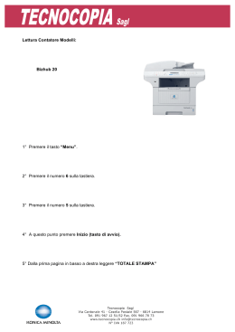
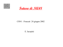
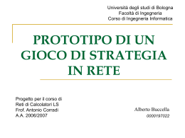
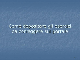
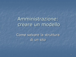
LIBRETTO
LIBRETTO USO
USO EE MANUTENZIONE
MANUTENZIONE
USE
USE AND
AND MAINTENANCE
MAINTENANCE MANUAL
MANUAL
FORNO
FORNO PER
PER CILINDRI
CILINDRI
PRE-HEATING
PRE-HEATING FURNACE
FURNACE
DAKO
DAKO 5210-5230
5210-5230
DAKO 5210-5230
The Manufacturer reserves the right to modify the technical and functional features of the appliances described in this instruction manual without giving prior notice;
also, will not answer for any inaccuracies, attributable to printing or transcription errors, in this instruction manual.
Il Costruttore si riserva il diritto di apportare modifiche alle caratteristiche tecniche e funzionali dei prodotti presentati in questa pubblicazione senza dare alcun preavviso;
inoltre, non risponde di possibili inesattezze, imputabili ad errori di stampa o di trascrizione, contenute nel presente libretto.
2
ITALIANO
DAKO 5210-5230
Indice / Index
ITALIANO
SPECIFICHE TECNICHE ............................................................................................... pag.6
SCOPO DELL’APPARECCHIO ....................................................................................... pag.6
PRECAUZIONI ................................................................................................................ pag.6
INSTALLAZIONE ............................................................................................................ pag.6
Installazione aspiratore ............................................................................................. pag.6
Installazione tubo di scarico ...................................................................................... pag.6
ATTIVAZIONE ................................................................................................................. pag.6
ACCENSIONE ................................................................................................................ pag.7
SET UP ........................................................................................................................... pag.7
Creazione di un programma ...................................................................................... pag.8
Modifica di un programma ......................................................................................... pag.9
ESECUZIONE DI UN PROGRAMMA ........................................................................... pag.10
Sospensione, modifica, fine di un programma in esecuzione .................................. pag.11
Sospensione di un programma in esecuzione .................................................... pag.11
Modifica di un programma in esecuzione ........................................................... pag.11
INTERRUZIONE DEFINITIVA DI UN PROGRAMMA .................................................... pag.11
MANCANZA DI TENSIONE ........................................................................................... pag.11
MODIFICA TARATURA .................................................................................................. pag.11
AUTODIAGNOSTICA ................................................................................................... pag.12
TEST INDICATORI LUMINOSI E TASTI ....................................................................... pag.12
LEGENDA FIGURE ....................................................................................................... pag.12
GARANZIA .................................................................................................................... pag.13
Certificato di Garanzia su modello UNIDI-ANCAD ....................................................... pag.13
Regolamento ................................................................................................................. pag.13
ENGLISH
TECHNICAL SPECIFICATION ......................................................................................
SCOPE OF DEVICE .....................................................................................................
PRECAUTIONS ............................................................................................................
INSTALLATION .............................................................................................................
Installation of the exhaust fan ..................................................................................
Exhaust pipe installation ..........................................................................................
POWER UP ...................................................................................................................
START UP .....................................................................................................................
SET UP .........................................................................................................................
Production of a program ..........................................................................................
How to change an existing programme ........................................................................
RUNNING A PROGRAM ...............................................................................................
Suspension, modification, end of a programme run ................................................
Suspension of a programme run .......................................................................
Modification of a programme run .......................................................................
DEFINITIVE INTERRUPTION OF A PROGRAMME ....................................................
POWER FAILURE .........................................................................................................
CALIBRATION MODIFICATION ...................................................................................
SELF-TEST ...................................................................................................................
LUMINOUS INDICATOR AND KEY TEST ....................................................................
LEGEND OF FIGURES ................................................................................................
WARRANTY ..................................................................................................................
Certificate of garantee (approved by UNIDI) .................................................................
Guarantee regulations ..................................................................................................
pag.15
pag.15
pag.15
pag.15
pag.15
pag.15
pag.15
pag.16
pag.16
pag.17
pag.18
pag.19
pag.20
pag.20
pag.20
pag.20
pag.20
pag.20
pag.21
pag.21
pag.21
pag.22
pag.22
pag.22
SCHEMA ELETTRICO / ELECTRIC PLANE .................................................. pag.23
PARTI DI RICAMBIO / SPARE PARTS DAKO 5210 ...................................... pag.24
PARTI DI RICAMBIO / SPARE PARTS DAKO 5230 ...................................... pag.27
DICHIARAZIONE DI CONFORMITÁ DECLARATION OF CONFORMITY .... pag.31
3
DAKO 5210-5230
14
1
3
2
15
7
4
6
5
3)
1)
8
9
10
3a)
12
11
13
2)
3b)
4
ITALIANO
DAKO 5210-5230
4)
7)
5)
8)
6)
5
DAKO 5210-5230
DAKO 5210-5230
Il presente manuale delle istruzioni d’uso è parte integrante della fornitura dell’apparecchiatura e deve accompagnare la stessa in ogni trasferimento.
Il manuale va conservato con cura per tutto il ciclo di
vita dell’apparecchio ed essere comunque reperibile per
almeno 10 anni. Esso va conservato in luogo noto e
reso disponibile a tutte le persone interessate.
Non collegare o mettere in funzione l’apparecchio prima di aver letto questo manuale.
SPECIFICHE TECNICHE
Potenza
Potenza di uscita
Altezza
Larghezza
Profondità
Peso netto
220/240V - 50/60 Hz
1760 W
44 cm
27 cm
47 cm
29 kg
SCOPO DELL’APPARECCHIO
I forni DAKO 5210-5230 servono per il preriscaldo dei
cilindri, confezionati con qualsiasi tipo di rivestimento
utilizzato nei laboratori odontotecnici.
Entrambi i forni DAKO, possono essere dotati di aspiratori per l’estrazione dei fumi dalla camera di riscaldo;
il funzionamento degli, può essere controllato direttamente dal pannello di controllo. Qualsiasi utilizzo diverso da quanto sopra descritto è da considerarsi improprio e libera il costruttore da ogni responsabilità riguardo a danni di qualsiasi natura, facendo inoltre decadere i diritti di garanzia sull’apparecchio stesso.
PRECAUZIONI
•
Alcuni materiali utilizzati per la confezione dei
preformati, da soli o unitamente ad altri componenti
del rivestimento, possono generare dei vapori ad
altissima reattività chimica nei confronti delle leghe
che costuituiscono le resistenze di riscaldo.
E’ sempre ottima cosa provvedere all’estrazione della
cera mediante essiccatore od un forno a gas in modo
da introdurre nel forno elettrico i cilindri già privati
delle sostanze chimiche più attive.
Assicurarsi che l’impianto elettrico sia dotato di dispositivo salvavita
•
•
INSTALLAZIONE
Installare l’apparecchio su di una superficie piana e stabile in grado di sopportarne il peso.
Prestare attenzione a:
• non immergere il cavo di alimentazione in acqua
• tenere il cavo di alimentazione lontano da fonti di
calore.
6
•
Non lasciare pendere il cavo di alimentazione da
bordi di mobili
Prima di proseguire verificare che:
• il cavo di alimentazione o la spina non siano danneggiati.
• l’apparecchio non si presenti danneggiato
INSTALLAZIONE DEL TUBO DI SCARICO O DELL’ASPIRATORE
DAKO può essere fornito con il tubo di scarico fumi o
con l’aspiratore. Nel seguito sono riportate le relative
istruzioni di installazione
Installazione aspiratore
•
•
•
•
•
Posizionare la guarnizione fornita in corrispondenza del foro posto sulla parte posteriore della camera
(fig.4)
Inserire l’aspiratore come illustrato in fig.5
fissare l’aspiratore per mezzo delle quattro viti fig.6
posizionare il bicchiere per la raccolta
condensa.(fig.3a))
Se presente rimuovere l’etichetta (12, fig.2)
NON RIMUOVERE
DON'T REMOVE
•
Inserire la spina dell’aspiratore nella presa sulla base
del forno (15, fig. 3)
Installazione tubo di scarico
•
•
•
•
Posizionare la guarnizione fornita in corrispondenza del foro posto sulla parte posteriore della camera
(fig.7)
Inserire il tubo di scarico come illustrato in fig.7
fissare l’aspiratore per mezzo delle quattro viti (fig.8)
posizionare il bicchiere per la raccolta condensa
(fig.3b)
ATTIVAZIONE
Inserire la spina dell’apparecchio
in una presa adatta per tensione e potenza ai dati riportati sulla targa dell’apparecchio munita di terra
Il collegamento alla terra è obbligatorio a norma di legge. L’installazione va eseguita da un installatore qualificato che possa assicurarsi di tale adempimento.
Il fabbricante declina ogni responsabilità per eventuali danni a caose o a persone derivanti dalla mancata ossservanza dei punti precedenti.
ITALIANO
ITALIANO
DAKO 5210-5230
ACCENSIONE
Il forno si accende per mezzo dell’interruttore generale
(2, fig.1) posto sul fianco destro della base del forno
stesso. Accendendo il forno si illumina il display (4, fig.1)
mostrando la scritta “SARATOGA”, la temperatura della camera, la data e l’ora.
SARATOGA
22°C
13/06/02
15:56
A
Il grafico a led (7, fig.1) è spento.
SET UP
Al ricevimento del forno occorre impostare alcuni parametri riguardanti il funzionamento generale del forno:
DATA, ORA, STAMPA, LINGUA , GRADI:
Attenzione!
L’opzione STAMPA serve se vi è una stampante collegata. La stampante è opzionale e non è fornita con il
forno.
Per accedere alla procedura di setup premere il tasto
SET DATA
D
13/05/02
con le due cifre del giorno (le prime due a sinistra) lampeggianti. per selezionare il giorno desiderato premere
i tasti
o
. Premere quindi RUN/ABORT,
lampeggeranno le cifre del mese. Selezionare il mese
desiderato per mezzo dei tasti
o . Premere quindi
RUN/ABORT, lampeggeranno le cifre dell’anno. Selezionare l’anno desiderato per mezzo dei tasti
o .
premere RUN/ABORT la nuova data verrà memorizzata e si ritornerà al punto c)
Attenzione!
In queste fase e durante l’immissione di un programma, spiegata in seguito, se non si effettuano variazioni
per alcuni secondi il display ritorna automaticamente al
passo precedente.
ORA: Per cambiare l’ora visualizzata dal forno selezionare ORA e premere RUN/ABORT comparirà:
SET ORA
E
FUNC
17:53
Sul display comparirà:
SET
CALIB
PROG
B
VER
DIAGN
La “S” di set dovrebbe già essere sottolineata, ciò indica che è stata selezionata questa opzione. Se non lo
fosse premere il tasto
con le due cifre dell’ora (le prime due a sinistra) lampeggianti. per selezionare l’ora desiderata premere i tasti
o . Premere quindi RUN/ABORT, lampeggeranno
le cifre dei minuti. Selezionare i minuti per mezzo dei
tasti
o
premere RUN/ABORT la nuova ora verrà
memorizzata e si ritornerà al punto c)
STAMPA:Per cambiare la modalità di stampa della stampante eventualmente collegata al forno selezionare
STAMPA e premere RUN/ABORT comparirà:
MODALITÀ
o
F
TEMPO
finché la sottolineatura si sposta sotto la S di SET. Premere:
RUN
ABORT
Sul display comparirà:
DATA
ORA
STAMPA
L’opzione MODALITÀ serve a definire se si vuole che
venga stampato un grafico del ciclo di riscaldo o un testo che ad intervalli definiti riporti le variabili del ciclo
(temperatura e tempo). L’opzione TEMPO serve per
definire gli intervalli di tempo tra la stampa dei punti del
grafico o dei testi.
Selezionando MODALITA’ compare:
C
LINGUA
MODO GRAFICO
GRADI
G
MODO TESTO
Come prima si intende selezionata l’opzione la cui prima lettera è sottolineata
DATA: Per cambiare la data visualizzata dal forno selezionare DATA e premere RUN/ABORT comparirà:
Selezionando MODO GRAFICO e premendo RUN/
ABORT verrà stampato un grafico del ciclo di riscaldo
Selezionando MODO TESTO, ad intervalli predefiniti
verrà stampato un teso riportante data ora e temperatura.
7
DAKO 5210-5230
Premere RUN ABORT si ritorna al punto f).
Selezionando TEMPO e premendo RUN/ABORT comparirà:
GRAFICO
CREAZIONE DI UN PROGRAMMA
Per poter immettere un nuovo programma il forno deve
essere in condizioni di riposo in cioè deve essere
visualizzato il seguente display:
H
TESTO
SARATOGA
22°C
13/06/02
15:56
A
Selezionare GRAFICO e premere RUN/ABORT per
definire gli intervalli di stampa dei punti del grafico.
Comparirà:
REFRESH
GRAFICO
mm:ss
00:03
ed Il grafico a led (7, fig.1) deve essere spento.
In tali condizioni premere FUNC. Comparirà:
I
SET
selezionare per mezzo dei tasti o l’intervallo a cui
devono essere stampati i punti del grafico. Premere
RUN/ABORT per memorizzare il dato e tornare al punto h)
Selezionare TESTO e premere RUN/ABORT per definire gli intervalli di stampa del testo riportante i dati del
processo. Comparirà:
CALIB
PROG
B
DIAGN
VER
Per mezzo dei tasti
o
selezionare PROG e premere RUN/ABORT. Comparirà:
PROGRAMMAZIONE
C
CICLO NUMERO 0
REFRESH
TESTO
mm:ss
00:03
J
selezionare per mezzo dei tasti o l’intervallo a cui
devono essere stampato il testo. Premere RUN/ABORT
per memorizzare il dato e tornare al punto d)
Premere FUNC per tornare al punto f)
Premere ancora FUNC per tornare al punto c)
LINGUA: Per visualizzare le scritte che compaiono sul
display nella lingua desiderata selezionare LINGUA e
premere RUN/ABORT. Comparirà:
ITALIANO
K
ENGLISH
Selezionare la lingua desiderata per mezzo dei tasti
o . Premere RUN/ABORT per memorizzare il dato e
ritornare al punto c)
GRADI: Per variare la visualizzazione delle temperature da °C a °F o viceversa selezionare GRADI e premere RUN/ABORT. Comparirà:
MISURAZIONE
L
GRADI
°C °F
Selezionare °C o °F per visualizzare le temperature
nell’unità di misura desiderata. Premere RUN/ABORT
per memorizzare il dato e tornare al punto c)
Per mezzo dei tasti
o
selezionare il numero di
programma desiderato e premere RUN/ABORT. Comparirà:
MODAL. INIZIO
D
TASTO
OROLOGIO
Selezionando tasto il programma partirà dopo un intervallo di tempo definito (p.e. si potrà far partire il ciclo
dopo 1 ora).
Selezionando OROLOGIO il ciclo partirà ad una data e
ora prefissate (p.e. si potrà far partire il ciclo alle 8:37
del 7/6/02)
Se si seleziona TASTO si passa direttamente al punto g).
Se si seleziona OROLOGIO seguito da RUN/ABORT
compare:
SET DATA
E
13/05/02
con le due cifre del giorno (le prime due a sinistra) lampeggianti. per selezionare il giorno di inizio desiderato
utilizzare i tasti
o
premere quindi RUN/ABORT,
lampeggeranno le cifre del mese. Selezionare il mese
desiderato per mezzo dei tasti
o premere quindi
RUN/ABORT, lampeggeranno le cifre dell’anno. Seleo
zionare l’anno desiderato per mezzo dei tasti
premere RUN/ABORT la data di inizio del ciclo verrà
memorizzata e comparirà:
SET ORA
F
8
17:53
con le due cifre dell’ora di inizio ciclo (le prime due a
sinistra) lampeggianti. per selezionare l’ora desiderata
utilizzare i tasti
o . Premere quindi RUN/ABORT,
lampeggeranno le cifre dei minuti. Selezionare i minuti
per mezzo dei tasti
o
premere RUN/ABORT la
nuova ora verrà memorizzata e comparirà:
Per mezzo dei tasti
o
selezionare il tempo di stabilizzazione (in ore:minuti) desiderato e premere RUN/
ABORT. Comparirà:
VENTILATORE
K
PRESENTE
TEMPO
ASSENTE
PRE-CICLO
G
IN HH-LL:
00:00
Per mezzo dei tasti o selezionare l’opzione PRESENTE se si vuole che l’aspiratore funzione durante la
presente fase di salita e stabilizzazione della temperatura; selezionare l’opzione ASSENTE se il ventilatore
non deve funzionare nella presente fase di salita e stabilizzazione della temperatura. Premere RUN/ABORT
per memorizzare il dato. Comparirà:
PROSSIMO PASSO
I
SI
Questo tempo è un tempo di attesa, trascorso il quale il
forno inizierà a riscaldare. Selezionare il tempo di preciclo desiderato per mezzo dei tasti
o
premere
RUN/ABORT per memorizzare il dato. Comparirà:
RAGGIUNGERE LA
H
TEMPERAT:
0°C
NO
Nel caso si voglia raggiungere e stabilizzare un’altra
temperatura selezionare per mezzo dei tasti o l’opzione SI, altrimenti selezionare NO.
Se si seleziona NO si andrà direttamente al punto m
Se si seleziona verranno ripetuti i punti da h) ad l)
Si possono programmare tre temperature diverse per
ogni programma, quindi se si risponde SI alla richiesta
PROSSIMO PASSO (SI/NO) (punto l), tale richiesta
verrà ancora ripetuta per la terza temperatura.
Terminata la programmazione relativa all’ultimo
stazionamento stazionamento premere il tasto RUN/
ABORT compare:
MANTENERE TEMP
M
Per mezzo dei tasti
o
selezionare la temperatura
desiderata e premere RUN/ABORT. Comparirà:
GRADIENTE
H
1°C / Min
Per mezzo dei tasti o selezionare il gradiente desiderato e premere RUN/ABORT. Comparirà:
STABILIZZAZIONE
J
IN HH:MM:
00:00
SI
NO
Selezionando SI la temperatura verrà mantenuta indefinitamente anche se il tempo di stabilizzazione è trascorso. Sarà l’operatore a dover interrompere il programma.
Selezionando NO al termine del periodo di stabilizzazione la temperatura non verrà mantenuta e perciò il
forno si raffredderà fino a temperatura ambiente.
Premere RUN/ABORT per memorizzare il dato. Verrà
emesso un segnale acustico per segnalare il termine
dell’immissione del programma e si tornerà al punto c).
A questo punto si può selezionare un altro numero di
programma ed immettere i dati seguendo la procedura
descritta o tornare al punto a) premendo FUNC
MODIFICA DI UN PROGRAMMA
Per modificare un programma procedere esattamente
come spiegato per la creazione di un programma camo
valori già presenti
biando per mezzo dei tasti
9
ITALIANO
DAKO 5210-5230
DAKO 5210-5230
ESECUZIONE DI UN PROGRAMMA
Sul grafico a LED si accenderà la prima spia:
Nota: nella seguente spiegazione sono visualizzati dei
dati numerici. Questi sono riportati a solo titolo di esempio. Durante l’esecuzione di un programma tempi e temperature visualizzati varieranno a seconda di quanto
previsto dal programma stesso.
Con il forno in condizioni di riposo cioè quando il display mostra:
SARATOGA
22°C
13/06/02
15:56
A
Trascorso il tempo mancante all’inizio del ciclo sul display apparirà:
Numero del programma in esecuzione
Passo in esecuzione
Programma attivo
Temp. da raggiungere
Premere RUN/ABORT. Compare
ESECUZIONE
B
E
0
CICLO NUMERO
P0.2
RUN
10°C/m
ON
250°C
22°C
Gradiente
Con i tasti
o
selezionare il ciclo che si vuole eseguire e premere RUN/ABORT
Se il programma prevede l’avvio mediante TASTO comparirà il display d)
Se il programma prevede la partenza con orologio comparirà:
Riscaldamento attivo (ON) o inattivo (OFF) questo dato
varia durante il programma poiché il riscaldamento viene
attivato o disattivato per mantenere il gradiente e/o la
temperatura selezionata per la fase in corso.
Attenzione: per motivi di sicurezza l’apertura dello sportello provocherà l’interruzione del riscaldamento. La
scritta RUN verrà sostituita da STOP e la scritta ON da
OFF. Alla richiusura dello sportello il programma riprenderà regolarmente
PARTENZA CICLO
C
15:33
17/07/02
Temperatura
della camera
Nota: la data e l’ora riportate sono solo un esempio.
Verranno visualizzate la data e l’ora di inizio previste
dal programma.
Premendo FUNC si interromperà il programma e si tornerà al punto a)
Raggiunte le data e l'ora programmate il forno
eseguirà l'eventuale preciclo di attesa e comparirà
il numero del programma in esecuzione
Raggiunta la temperatura prevista per la fase in corso
sul display apparirà:
Passo in esecuzione
Programma attivo
Numero del programma in esecuzione
Passo in esecuzione
Temp. da raggiungere
Programma attivo
P0.1
RUN
22°C
-8:22
OFF
22°C
Temp. da stabilizzare
D
Tempo mancante
all'inizio del ciclo
Riscaldamento
non attivo
Temperatura
della camera
Poichè In questa fase il riscaldamento non è attivo la
temperatura della camera e quella da raggiungere sono
uguali
10
P0.3
RUN
250°C
-1:27
ON
250°C
F
Tempo da
stabilizzazione
Temperatura
della camera
Riscaldamento attivo (ON) o inattivo (OFF) questo dato
varia durante il programma poiché il riscaldamento viene
attivato o disattivato per mantenere il gradiente e/o la
temperatura selezionata per la fase in corso.
Sul grafico a led si accende la spia relativa alla salita di
temperatura:
Sul grafico led si accenderà la spia relativa alla fase di
stabilizzazione:
P0.2
STOP
250°C
10°C/m
ON
22°C
B
ITALIANO
DAKO 5210-5230
Se invece la sospensione del programma è avvenuta
durante una fase di stabilizzazione comparirà
STABILIZZAZIONE
C
Nel caso sia prevista la stabilizzazione di più temperature i passi e) ed f) saranno ripetuti, ovviamente sul grafico led si accenderanno le spie relative ai passi in esecuzione.
Trascorso l’ultimo tempo di stabilizzazione previsto dal
programma sul display compare:
FINE CICLO
250°C
G
OFF
250°C
e viene emesso un segnale acustico.
La temperatura verrà mantenuta indefinitamente o no
a seconda di quanto previsto dal programma in esecuzione.
Premere FUNC per tornare al punto a)
SOSPENSIONE, MODIFICA, FINE DI UN
PROGRAMMA IN ESECUZIONE
Sospensione di un programma in esecuzione
L’esecuzione di un programma può essere sospesa
tenendo premuto il tasto RUN/ABORT per almeno due
secondi. In tal caso la scritta RUN viene sostituita dalla
scritta STOP. Il riscaldamento ed il conteggio del tempo
vengono sospesi. Per riavviare il programma premere
nuovamente RUN/ABORT
Modifica di un programma in esecuzione
Per modificare un programma in corso di esecuzione
occorre prima sospenderlo come spiegato al punto precedente, quindi premere FUNC. Comparirà:
USCITA
A
MODIFICA
IN HH:MM:
00:02
in cui il tempo di stabilizzazione lampeggerà. Se necessario modificarlo coni tasti
o
premere RUN/
ABORT per tornare al punto b).
Selezionare RUN e premere RUN/ABORT per tornare
all’esecuzione del programma.
Attenzione: tutte le modifiche effettuate varranno solo
per l’esecuzione in corso e non verranno memorizzate.
INTERRUZIONE DEFINITIVA DI UN PROGRAMMA
Per interrompere definitivamente un programma occorre
prima sospenderlo come spiegato in precedenza.
Selezionare quindi la voce USCITA e premere RUN/
ABORT oppure premere il tasto FUNC per tornare alle
condizioni di riposo.
MANCANZA DI TENSIONE
Se durante l’esecuzione di un programma avverrà una
mancanza di tensione, al ritorno della stessa il forno
riprenderà il programma dal punto in cui si era interrotto.
Nota:Se la mancanza di tensione è avvenuta durante
una stabilizzazione il conteggio del tempo riprenderà
dall’inizio della stabilizzazione stessa.
MODIFICA TARATURA
E’ possibile modificare la taratura sia del tempo che della
temperatura.
Per accedere a queste funzioni premere FUNC con il
forno a riposo. Comparirà:
RUN
SET
CALIB
PROG
A
Selezionare per mezzo dei tasti
o
la voce MODIFICA. Premere RUN/ABORT
Se la sospensione è avvenuta durante la fase di salita
appariranno le seguenti specifiche:
la temperatura da raggiungere lampeggerà (con i tasti
o
selezionare la nuova temperatura), premere
RUN/ABORT: inizierà a lampeggiare il gradiente. se necessario modificarlo con i tasti
o .
DIAGN
VER
Selezionare l’opzione CALIB per mezzo dei tasti
e premere RUN/ABORT. Comparirà:
o
OROLOGIO
B
TEMPERATURA
11
DAKO 5210-5230
Se si desidera correggere la misura del tempo selezionare OROLOGIO e premere RUN/ABORT. Comparirà:
Per la soluzione dei problemi descritti rivolgersi ad un
tecnico autorizzato dalla Ditta SARATOGA.
CALIBRIZIONE
C
OROLOGIO
la termocoppia.
+0
E’ possibile modificare il valore di calibrazione con i tasti
o . Tener presente che incrementando per ogni
incremento di un’unità l’orologio accelera di 10,7 secondi al mese. Se il segno diventa negativo l’orologio
rallenta nella stessa misura.
Premere RUN/ABORT per memorizzare il dato e ritornare al punto b)
Premere quindi FUNC per tornare al punto a)
Se si desidera correggere la misura della temperatura
selezionare TEMPERATURA e premere RUN/ABORT.
Comparirà:
TEST INDICATORI LUMINOSI E TASTI
E’ possibile testare il buon funzionamento degli indicatori e dei tasti. Per eseguire tale operazione procedere
come segue.
Con forno in condizioni di riposo premere FUNC. Comparirà
SET
A
VER
CONSOLE
+0°C
TEMPER:
DIAGN
PROG
Per mezzo dei tasti ( o selezionare DIAGN e premere RUN/ABORT, comparirà
OFFSET
D
CALIB
Aumentando o diminuendo il valore di calibrazione questo provocherà un incremento o un decremento sull’intera scala delle temperature.
B
SENSORI
Per mezzo dei tasti (
o
selezionare CONSOLE e
premere RUN/ABORT, comparirà
LED E TASTI
Premere RUN/ABORT per tornare al punto b)
Premere quindi FUNC per tornare al punto a)
Attenzione: porre estrema cautela nel modificare questi parametri. Prima di effettuare variazioni consultare il
servizio tecnico.
Alcune situazioni anomale o guasti vengono segnalate
sui display sotto forma di codici di errore o scritte.
La temperatura richiesta non può essere raggiunta
in tal caso compare:
LOW T
STOP
250°C
OFF
22°C
Le cause del problema possono essere le seguenti:
Resistenze bruciate
Relè statico interrotto
Termocoppia interrotta
Nel caso la termocoppia sia interrotta compare:
P0.2
TC ERR
STOP
250°C
OFF
22°C
In tali condizioni il forno non riscalda. Occorre sostituire
12
premere RUN/ABORT, comparirà
D
AUTODIAGNOSTICA
P0.2
C
RUN PER INIZIARE
MENU PER USCIRE
Premendo il tasto ripetutamente si accenderanno in
sequenza tutti i led del grafico da sinistra a destra
Premendo il tasto
ripetutamente si spegneranno i
led accesi da destra a sinistra
Premendo RUN/ABORT si accenderanno automaticamente in sequenza tutti i led del grafico per poi spegnersi. questo test continuerà finché non si premerà
RUN/ABORT.
Per uscire dai test e tornare al punto c) premere FUNC.
Premere ancora FUNC per tornare al punto b)
Premere ancora FUNC per tornare al punto a)
LEGENDA FIGURE
1. sportello
2. interruttore generale
3. manopola manovra sportello
4. display
5. pulsantiera
6. pannello controllo
7. grafico led
8. tubo di scarico fumi
9. termocoppia
10. fusibili
11. cavo di alimentazione
12. presa per collegamento aspiratore con etichetta di
protezione
13. porta seriale
14. aspiratore fumi
15. spina aspiratore
GARANZIA
Certificato di Garanzia su modello UNIDI-ANCAD
1. Col presente documento il fabbricante certifica la corretta costruzione del prodotto, l’impiego di materiali
di prima qualità, l’effettuazione di tutti i collaudi necessari e la sua aderenza alle norme vigenti. Il prodotto è coperto da un periodo di Garanzia di mesi
12 dalla data di consegna all’utente, che dovrà essere comprovata dalla restituzione dell’allegato tagliando controfirmato dall’Utente.
La garanzia è limitata alla sostituzione o sistemazione delle singole parti o dei pezzi che risultano di
fabbricazione difettosa, con esclusione delle spese
di manodopera, trasferta del personale tecnico, spese di trasporto, di imballaggio, ecc.
Sono esclusi dalla Garanzia guasti o danni derivanti
da cattiva manutenzione, da scorretta alimentazione, negligenza, imperizia o cause non imputabili al
fabbricante.
Sono da escludersi dalla Garanzia le avarie causate da mancata manutenzione ordinaria dovuta a trascuratezza dell’utilizzatore.
La presente Garanzia non comporta alcun risarcimento di danni diretti o indiretti di qualsiasi natura
verso persone o cose, dovuti all’eventuale inefficienza dell’apparecchiatura.
2. La Garanzia decade automaticamente qualora le
apparecchiature vengano riparate, modificate o comunque manomesse dall’acquirente o da terzi non
autorizzati.
3. Per gli interventi in Garanzia l’acquirente dovrà rivolgersi unicamente al venditore, oppure ai centri di
assistenza indicati dal fabbricante o al produttore
stesso.
La Garanzia dà diritto alla sostituzione gratuita della
parte difettosa. É comunque escluso il diritto alla sostituzione dell’intero apparecchio.
4. Nel caso di contestazione sull’applicazione della Garanzia, sulla qualità o sulle condizioni delle
apparecchiature consegnate, l’acquirente non potrà
sospendere o ritardare il pagamento del prezzo o
delle rate di prezzo.
5. Nessun risarcimento potrà essere richiesto dall’ac-
quirente per fermo delle apparecchiature.
6. La Garanzia decade se:
a) l’apparecchiatura presenta danneggiamenti provocati da caduta, da esposizioni a fiamme, da rovesciamenti di liquidi, da fulmini, da calamità naturali,
o comunque da cause non imputabili a difetti di fabbricazione;
b) non vi è stata una corretta installazione;
c) vi è stato collegamento alla rete (tensione nominale di alimentazione errata);
d) il numero di matricola risulti asportato, cancellato
o alterato.
7. I componenti da sostituirsi in garanzia, devono essere restituiti alla Casa che ha provveduto o provvederà alla spedizione del ricambio. Qualora il pezzo
cambiato non venga restituito, verrà addebitato all’ordinante.
8. Per ragioni fiscali le parti di ricambio verranno
concesse in garanzia unicamente nel caso in cui
ci sia pervenuto il tagliando di garanzia contenente tutti i dati relativi al cliente.
Regolamento
1. La mancata restituzione del Certificato di Garanzia
implica l’immediata decadenza della medesima.
La Garanzia non copre le spese di manodopera e
trasferta che saranno sempre e comunque a carico
dell’acquirente.
2. Il pagamento delle fatture di manodopera, trasferta
e diritto di chiamata, dovrà avvenire a presentazione delle medesime. Il mancato pagamento implicherà l’automatico decadimento della Garanzia.
3. Il fabbricante nonché il Deposito Dentale non sono
tenuti a dare in uso apparecchiature sostitutive per
il periodo di riparazione.
4. Per ogni altro caso non contemplato dal presente
Certificato di Garanzia e dal regolamento si fa riferimento alle norme del Codice Civile.
Legge 31 dicembre 1996, n. 675
I Clienti sono informati, ai sensi dell’art. 10 della Legge
31 dicembre 1996, n. 675, e pertanto approvano espressamente che i dati forniti per l’attivazione delle clausole
di garanzia possono essere trattati da SARATOGA
S.p.a., con sede legale in Pordenone, per:
a) l’adempimento degli obblighi previsti da leggi, regolamenti e dalla normativa comunitaria, ovvero da disposizioni impartite da autorità a ciò legittimate dalla legge, nonché da organi di vigilanza;
b) finalità strettamente connesse e strumentali all’esecuzione ed alla gestione del contratto con Lei/Voi
stipulato;
c) finalità gestionali, statistiche, commerciali, di
marketing e promozionali.
13
ITALIANO
DAKO 5210-5230
DAKO 5210-5230
Il conferimento dei dati personali di cui alla lett. a) è
obbligatorio ed il rifiuto di fornirli determinerà l’impossibilità dell’instaurazione e/o della prosecuzione
del rapporto commerciale. Il conferimento dei dati
personali di cui alla lett. b) non è obbligatorio, ma il
rifiuto di fornirlo determinerà l’impossibilità
dell’instaurazione e/o della prosecuzione del contratto con Lei/Voi concluso, nonché delle operazioni
di revisione e riparazione relative alla fornitura alla
quale il contratto si riferisce. Il conferimento dei dati
14
di cui al punto c) non è obbligatorio, ma il rifiuto di
fornirli determinerà l’impossibilità per Lei/Voi di fruire di iniziative commerciali della Società, nonché di
essere destinatario di materiale promozionale della
medesima.
Il trattamento per le finalità di cui alle lett. a) e b) e c)
non richiede il consenso, ai sensi dell’art. 12, comma
1, lett. a) e b) L. 675/96.
DAKO 5210-5230
The present usage instruction Manual forms integral part
of the machine supply and it must accompany the
machine during any transfer.
This Manual must be carefully preserved during the
whole lifetime of the machine and it must be held within
reach for at least ten years. The place where it is kept
must be well known and at hand to all the involved
people.
Do not connect or start up the machine before reading
this Manual carefully.
TECHNICAL SPECIFICATION
Power supply
Power output
Height
Width
Depth
Net weight
220/240V - 50/60 Hz
1760 W
44 cm
27 cm
47 cm
29 kg
SCOPE OF DEVICE
The furnaces DAKO 5210-5230 are intended for
preheating the cylinders, coated with any kind of
covering as used in the dental mechanics laboratories.
Both WARMY furnaces may be equipped with exhaust
fans in order to remove the fumes from the heating
chamber; their operation may be controlled directly
through the control panel. Any use other than described
above has to be considered an improper use, which
relieves the manufacturer of any responsibility for
damages of any kind whatever, furthermore involving
the user’s forfeiture of any right of guarantee covering
the device.
PRECAUTIONS
•
•
•
Some ones of the materials used for pre-forming,
either alone or in conjunction with other components
of the coating, may release vapours with highest
chemical reactivity, which strongly react the alloys
of the heating resistors.
It is recommended to remove the wax by means of a
drier or a gas furnace so that the cylinders taken
into the electric furnace are already free from the
most active chemical substances.
Make sure the electric system is equipped with safety
cutout.
INSTALLATION
Install the device on a flat surface, suitable to bear its
weight.
The following precautions should be taken:
• Avoid immersing the power cable into the water
• Keep the cable far from heat sources.
• Avoid the power cable hangs down from the edges
of the furniture.
Before going on, check that:
• The power cable and plug are not damaged.
• The device is in full working order (no visible
damages)
INSTALLATION OF THE FUME EXHAUST PIPE OF
EXHAUST FAN
Warmy may be supplied with a fume exhaust pipe or
with an exhaust fan. The instructions are as follows:
Installation of the exhaust fan
•
•
•
•
•
Position the seal supplied in the vicinity of the hole
positioned on the rear part of the chamber (fig. 4)
Insert the exhaust fan as illustrated in fig. 5
Secure the exhaust fan using the four screws fig. 6
Position the condensation collection beaker (fig. 3a)
Remove the label if present (12, fig. 2).
NON RIMUOVERE
DON'T REMOVE
•
Insert the pin of the exhaust fan into the socket at
the base of the furnace (15, fig. 3)
Exhaust pipe installation
•
•
•
•
Position the seal supplied in the vicinity of the hole
on the rear side of the chamber (fig. 7)
Insert the exhaust pipe as shown in fig. 7
Secure the suction using the four screws (fig. 8)
Position the condensation collection beaker (fig. 3b)
POWER UP
Plug the device in a socket having voltage and power
ratings corresponding to the rated output of the device,
and fitted with protective earthing.
Grounding is mandatory by the operation of Law.
The installation has to be carried out by a skilled
installer, qualified to inspect the above mentioned
provision is fulfilled.
The manufacturer declines all responsibility for any
injury to people or damages to things possibly
arising from the non-compliance with the abovementioned rules.
15
ENGLISH
DAKO 5210-5230
DAKO 5210-5230
START UP
Switch on the furnace by means of the main switch (2,
fig. 1) placed on the right side of the furnace base. When
the furnace is started, the display (4, fig. 1) turns on
and the “SARATOGA” label appears, together with
chamber temperature, date and time.
SARATOGA
22°C
13/06/02
15:56
A
Il The graphic led symbol is off (7, fig. 1)
SET UP
On receipt of the furnace it is necessary to set certain
parameters relating to the general function of the
furnace: DATE, TIME, PRINT, LANGUAGE, DEGREES:
Caution!
The PRINT option is necessary if the device is connected
to a printer. It is however an optional if not supplied with
the furnace.
For access to the set-up procedure press the following
key:
SET DATE
D
13/05/02
with the two figures of the date (the first two on the left)
flashing to select the required date press the following
keys or . Press RUN/ABORT, the two digits of the
month will appear. Select the desired month using these
keys or . Then press RUN/ABORT, the year digits
will flash . Select the required year using keys
or
press RUN/ABORT the new date will be memorized and
we return to point c)
Caution!
During this phase and when entering a programme as
explained below, if no variations are made for a few
seconds the display will return automatically to the
previous stage.
TIME: To change the time displayed by the furnace
select TIME and press RUN/ABORT the following
appears:
SET TIME
E
17:53
FUNC
The following appears on the display:
SET
B
CALIB
PROG
VER
DIAGN
The “S” of set should already be underlined; this
indicates that this option has already been selected. If
not, press the following key:
with the two digits, indicating the time (the first two on
the left), flashing. To select the required time, press the
key or .Press RUN/ABORT, the minute figures will
flash. Select the minutes using the key
or . Press
RUN/ABORT: the new hour will be memorized and we’ll
return to point c)
PRINT: To change the print mode on the printer that
may be connected to the furnace, select PRINT and
press RUN/ABORT. The following will appear:
MODE
F
or
until the shift under the S of SET is underlined and press;
RUN
ABORT
The following appears on the display:
DATE
C
TIME
LANGUAGE
The first option selected is the option with the underlined
first letter.
DATE: To change the date displayed on the furnace
select DATE and press RUN/ABORT the following
appears:
16
The MODE option is necessary to define the graphic
display of a heating cycle or a text, which indicates the
cycle variables at regular intervals
Select °C o °F to display the temperature in the required
measurement units. Press RUN/ABORT to memorize
and return to point c).
PRINT
DEGREES
TIME
GRAPHIC MODE
G
TEXT MODE
Selecting GRAPHIC MODE and pressing RUN/ABORT
it will be printed a graphic of heating cycle.
Selecting TEXT MODE, at regular intervals will be
printed the current date - time and temperature.
Press RUN/ABORT for return to step f).
DAKO 5210-5230
Selecting TIME in step (f) menu appears:
PRODUCTION OF A PROGRAM
To enter a new programme the furnace must be in idle
conditions and the following display must appear:
GRAPHIC
H
TEXT
SARATOGA
22°C
13/06/02
15:56
A
REFRESH
GRAPHIC
mm:ss
00:03
I
and the led graphic indication must be off (7, fig. 1).
Under these conditions, press FUNC. The following
appears:
SET
Using the key
or
set the time gap between the
data printed on the graphic. Press RUN/ABORT to return
to h) menu.
Select TEXT on h) menu for time interval settinf for text
printing:
REFRESH
Using the key
or
select the required programme
number and press RUN/ABORT. The following appears:
PROGRAMMING
C
mm:ss
00:03
Using the key
or
set the time gap between the
data printed on the graphic. Press RUN/ABORT to return
to h) menu.
Press FUNC to return to f) menu.
PROG
VER
DIAGN
TEXT
J
CALIB
B
CYCLE NUMBER 0
Using the key
or
select the required programme
number and press RUN/ABORT. The following appears:
START MODE
D
CLOCK KEY
Press FUNC again to return to c) menu.
LANGUAGE: Select this item and press RUN/ABORT
to select the preferred language for information
displaying. The following appears on the display:
ITALIANO
K
ENGLISH
Using the key or set the preferred language. Press
RUN/ABORT to set the preference and returning to c)
menu.
DEGREE: Select this item and press RUN/ABORT for
set the degree measurement unit (°C or °F). The
following appears:
MEASURE UNIT
L
DEGREE
°C °F
Select °C o °F to display the temperature in the required
measurement units. Press RUN/ABORT to memorize
and return to point c)
After selection of the programme key the programme
will begin after a programmed time interval. (i.e. the cycle
may be set to begin after 1 hour)
On selecting CLOCK the cycle will begin at a defined
date and time (i.e. the cycle may be made to begin at
8:37 on 7/6/02)
If KEY is selected we go straight on to point g)
If CLOCK is selected followed by RUN/ABORT, the
following will appear:
SET DATE
E
13/05/02
with the two date digits (the first two on the left) flashing.
To select the required start date, use key or . Then
press RUN/ABORT. The month figures will flash. Select
the required month using the key
or . Then press
RUN/ABORT: the year figures will flash. Select the
required year using the keys
or . Press RUN/
ABORT: the cycle start date will be memorized and will
appear as follows:
SET TIME
F
17:53
17
ENGLISH
Select GRAPHIC for time interval setting for graphical
printing:
DAKO 5210-5230
with the two cycle start time digits (the first two on the
left) flashing. To select the required time, use the key
or . Then press RUN/ABORT. The minute figures
will start flashing. Select the minutes using the key
or
. Press RUN/ABORT The new time will be
memorized and the following will appear:
Using the key
or
select the required stabilization
time (in hours and minutes) and press RUN/ABORT.
The following will appear:
FAN
K
PRESENT
G
ABSENT
PRE-CYCLE TIME
IN HH-LL:
00:00
Use the key
or
to select the PRESENT option, if
you wish the exhaust fan to function during the Present
Temperature ascent and stabilization stage; select the
option ABSENT if the fan is not required to operate in
the present temperature ascent and stabilization stage.
Press RUN/ABORT to memorize the data. The following
will appear:
NEXT STEP
L
YES
This time is the wait time, after which the furnace begins
heating up. Select the pre-cycle time required using the
keys or . Press RUN/ABORT to memorize the data.
The following will appear:
REACH THE TEMP.
H
0°C
NO
Should it be necessary to reach and stabilize another
temperature, select the option YES using the key or
. Otherwise select NO.
If NO has been selected we will go directly to point m.
While if YES has been selected points h) and l) will be
repeated.
It is possible to set three different temperatures for each
programme; therefore if yes is the response to the
request NEXT STAGE (YES/NO) (point l), this request
will again be repeated for the third temperature.
At the end of the programming of the last stationing,
press the RUN/ABORT key and the following will
appear:
MAINTAIN TEMP.
M
Using the key or , select the required temperature
and press RUN/ABORT. The following appears:
GRADIENT
I
1°C / Min
Using the key
or
select the desired gradient and
press RUN/ABORT. The following will appear
STABILIZATION
J
IN HH:MM:
00:00
YES
NO
By selecting YES the temperature will be maintained
for an indefinite time even if the stabilization time has
expired. It will be up to the operator to interrupt the
programme.
By selecting NO at the end of the stabilization time the
temperature will not be maintained and the furnace will
therefore cool to reach room temperature.
Press RUN/ABORT to memorize the data An acoustic
signal will occur to signal the end of the programme
input thereby returning to point c). It will now be possible
to select another programme number and to enter the
data according to the procedure described or to return
to point a) pressing FUNC
HOW TO CHANGE AN EXISTING PROGRAMME
To modify an existing program, carry out the abovementioned operations required for producing a program,
and modify the previously entered values using key
or .
18
DAKO 5210-5230
Once the time from the beginning of the cycle has
expired the following will appear on the display:
Note: in the following explanation certain numeric data
is displayed. These are by way of an example only.
During the running of a programme, the times and
temperatures displayed will vary according to that
envisaged by the programme itself.
With the furnace in idle conditions the display will indicate the following:
SARATOGA
22°C
13/06/02
15:56
A
Number of pregramme being run
Stage in progress
Active program
Temp. to be reached
P0.2
RUN
10°C/m
ON
250°C
E
22°C
Gradient
Chamber
temperature
Press RUN/ABORT. The following appears
Heating active (ON) or inactive (OFF) this data will vary
during the programme as the heating function is activated
or deactivated in order to maintain the gradient and/or the
selected temperature for the stage in progress.
ESECUTION OF
B
CYCLE NUMBER
ENGLISH
RUNNING A PROGRAM
0
Use the key
or
to select the required cycle, and
then press RUN/ABORT
Should the programme envisage start using a KEY, display d) will appear:
If the programme envisages timed start, the following
will appear:
The indicator light relative to temperature ascent will
light up on the led graphic display:
Caution: for safety reasons the opening of the door will
halt the heating function. The wording RUN will be
replaced with STOP and ON will change to OFF. The
programme will be resumed on closing the door again.
CYCLE START
C
15:33
17/07/02
Note: the time and date indicated are an example only.
The actual data and time envisaged by the programme
will actually appear:
On pressing FUNC, the programme is interrupted and
we return to point a)
Once the temperature has been reached for the stage
in progress the following will appear on the display:
Number of preogram being run
Programme number being run
Stage in progress
Running step
Active program
Active programme
Temp. to be stabilized
Temp. to be reached
P0.1
RUN
22°C
-8:22
OFF
22°C
Lack of time at
start of cycle
Heating not
active
P0.3
RUN
250°C
-1:27
ON
250°C
F
D
Temperature of
the chamber
As the heating is not active in this stage, the temperature in the chamber and that to be reached are the same.
On the LED display the following light will come on.
Stabilization
time
Chamber
temperature
Heating function active (ON) or inactive (OFF) this data will
vary during the programme as the heating function is
activated or deactivated in order to maintain the gradient
and/or the temperature selected for the stage in progress.
The indicator light relative to temperature ascent will
light up on the graphic led display.
The indicator light relative to the stabilization stage will
light up on the graphic led display.
19
DAKO 5210-5230
Should programme suspension have occurred during a
stabilization stage the following appears:
STABILISATION
C
IN HH:MM:
In the event that the stabilization of several temperatures
is envisaged, steps e) and f) will be repeated: obviously
on the led display the lights relative to the steps in
progress will light up.
At the end of the last stabilization time envisaged by
the programme, the following appears on the display:
END OF CYCLE
In which the stabilization time will flash. If necessary,
modify it using the keys or . Press RUN/ABORT to
return to point b).
Select RUN and press RUN/ABORT to return to
programme run mode.
Caution: all modifications made will only be valid for the
run in progress and will not be memorized.
250°C
DEFINITIVE INTERRUPTION OF A PROGRAMME
250°C
For the definitive interruption of a programme it is firstly
necessary to suspend it as described above. Therefore
select the command ESCAPE and press RUN/ABORT
or press the FUNC key to return to idle conditions.
G
OFF
and an acoustic signal occurs.
The temperature will be maintained indefinitely, or not,
according to that envisaged in the running programme.
Press FUNC to return to point a).
SUSPENSION, MODIFICATION, END OF A
PROGRAMME RUN
Suspension of a programme run
The run of a programme may be suspended by keeping
the RUN/ABORT key pressed for at least two seconds.
In which case the wording RUN is replaced by the
wording STOP. The heating and time count is
suspended. To re-start the programme press RUN/
ABORT again.
Modification of a programme run
To modify a programme in progress it is necessary to
suspend it as explained in the previous point, then press
FUNC. The following appears:
POWER FAILURE
In the event of a power failure during the running of a
programme, once the power returns the furnace will
resume the programme from the point where it was
interrupted.
Note: If power failure occurs during a stabilization stage
the calculation of the time will resume from the start of
the stabilization stage itself.
CALIBRATION MODIFICATION
Both the time and temperature settings may be modified.
To enter these functions press FUNC with the furnace
idle: the following will appear:
SET
CALIB
PROG
A
DIAGN
A
00:02
VER
EXIT
Select the CALIB option using key
or , and then
press RUN/ABORT. The following will appear:
CHANGE RUN
Use key or to select MODIFICATION. Press RUN/
ABORT
If suspension occurs during the rising stage the following
appears:
The temperature to be reached will flash. With key or
select the new temperature. Press RUN/ABORT: the
gradient will begin flashing. If necessary modify it using
keys
or
CLOCK
B
TEMPERATURE
To correct the time measurement, select CLOCK and
press RUN/ABORT. The following will appear:
CALIBRATION
B
20
P0.2
STOP
250°C
10°C/m
ON
22°C
C
CLOCK
+0
DAKO 5210-5230
Press RUN/ABORT to memorize the data and to return
to point b)
Then press FUNC to return to point a)
LUMINOUS INDICATOR AND KEY TEST
It is possible to test the correct working order of the
indicators and keys. For this operation proceed as
follows:
With the furnace in idle condition, press the FUNC key.
The following will appear:
SET
CALIB
A
To correct the temperature measurement, select TEMPERATURE and press RUN/ABORT. The following
appears:
OFFSET
D
DIAGN
CONSOLE
B
By increasing or reducing the calibration value, there
will be an increase or decrease of the entire temperature scale.
Press RUN/ABORT to return to point b)
Then press FUNC to return to point a)
Caution: take the greatest care when modifying these
parameters. Consult the technical assistance service
before making any variations.
VER
Use the key
or
to select DIAGN and then press
RUN/ABORT. The following will appear:
+0°C
TEMPER:
PROG
SENSORS
Use the key
or
to select CONSOLE and press
RUN/ABORT. The following will appear:
LEDS AND KEYS
C
press RUN/ABORT. The following will appear:
SELF-TEST
Some anomalous conditions or faults are signalled on
the display in the form of error codes or messages.
The required temperature cannot be reached in
which case the following appears:
P0.2
LOW T
STOP
250°C
OFF
22°C
The probable causes of these problems may be as
follows:
Burnt resistances
Static relay interrupted
Interrupted thermo-couple.
In the event of interrupted thermo-couple the
following appears:
D
RUN TO START
MENU TO ESCAPE
By pressing key repeatedly all the graph led indicators
will light up in sequence from left to right.
all the lighted led
By repeatedly pressing key
indicators will switch off from right to left.
On pressing RUN/ABORT, all the graph led indicators
will automatically light up and will then switch off again:
this test will continue until RUN/ABORT is pressed.
To escape from the test mode and return to point c),
press FUNC.
Press FUNC again to return to point b)
Press FUNC again to return to point a)
LEGEND OF FIGURES
P0.2
TC ERR
STOP
250°C
OFF
22°C
Under these conditions the furnace fails to heat up: The
thermo-couple needs to be replaced.
To resolve the problems described contact an authorized
technician of the “SARATOGA” company.
1. Door
2. Main switch
3. Door knob
4. Display
5. Push-button board
6. Control panel
7. Led graph
8. Fumes exhaust pipe
9. Thermocouple
10. Fuses
11. Power cable
21
ENGLISH
The calibration value may be modified using keys or
. Bearing in mind that in terms of increase for each
unit increase the clock will accelerate by 10.7 seconds
a month. If the sign is negative the clock will slow down
to an equal extent.
DAKO 5210-5230
12. Exhaust fan socket with safety tag
13. Serial port
14. Exhaust fan
15. Exhaust fan plug
WARRANTY
Certificate of garantee (approved by UNIDI)
1. Through the present document the manufacturer
certificates a correct construction of the product and
assures that first materials have been used; all
necessary approvals and trials have been made so
that the product is conform to the regulations in force.
The guarantee on this product is valid for a period of
12 months starting on the day of delivery to the
purchaser. The purchaser approves the guarantee
regulations by filling in and signing his part and
returning it to the manufacturer.
The guarantee only covers those parts to be
substituted or replaced because of construction faults
and doesn’t cover labour expensens, travelling
indemnity of technicians, transport expenses,
packing etc.
The guarantee excludes damages or failures caused
through a bad maintenance, a wrong feeding supply,
negligences, unskillfulness or other causes not
imputable to the manufacturer.
The guarantee excludes as well failures caused
through ommissed maintenance due to the
negligences of the user.
The guarantee doesn’t include any kind of refund
versus persons or objects for damages, direct or
indirect, due to eventual inefficiency of the
equipment.
2. The guarantee forfeits automatically in case that the
equipment has been repaired, modified or tampered
by the purchaser himself or by unauthorized third
parties.
3. For interventions under guarantee, the purchaser
must address himself to the selling-agent, or the by
him indicated technical-service or direct to the
manufacturer. The guarantee gives the right to
substitution of the defective part, but excludes the
substitution of the entire equipment.
4. In case of contestation concerning the application of
the guarantee regulations about the quality or
conditions of the delivered equipments, the
purchaser will in no way suspend or delay the
payment of the price or the rates of price.
22
5. No refund can be requested by the purchases for
the temporary stop of the equipment.
6. The guarantee forfeits if:
a) the equipment presents damages of dropping;
exposure to flames; overturning of liquid; natural
disasters; or any other causes not imputable to
fabrication defaults;
b) the installation wasn’t correct;
c) the connection to the main supply was wrong rated
feeding voltage;
d) the serial no has been taken of, cancelled or
altered.
7. The components, to be substituted under guarantee
must be sent back to the manufacturer for
reimboursement following carefully his shipment
instructions. For no reason we will accept the
returning of equipments or spare parts of them
without having given written authorization before. In
case of non observation of these conditions the
manufacturer reserves himself the right to send the
goods back to the sender.
8. Due to tax reasons the spare parts will be granted
under guarantee only if we have received back the
guarantee coupon properly filled in with all
customer’s data.
Guarantee regulations
1. The non restitution of the guarantee certificate
involves the immediate withdrawal of the certificate
itself.
The guarantee doesn’t cover labour expenses and
travelling indemnity which will always be on charge
of the purchaser.
2. The payment of the labour expenses, travelling
indemnity, and right of appeal bill will be have to
fullfilled immediate at the presentation of the bill itself.
Not fullfilling the payment of the bill involves immediate withdrawl of the guarantee itself.
3. Neither the manufacturer or the dental deposit are
obliged to provide substitutive equipment during the
repair period.
4. For any other cases not foreseen in the present
guarantee certificate and regulations reference is
made to the italian civil code.
DAKO 5210-5230
SCHEMA ELETTRICO
ELECTRIC PLANE
SCHEMA ELETTRICO / ELECTRIC PLANE
23
DAKO 5210-5230
PARTI DI RICAMBIO / SPARE PARTS
DAKO 5210
24
PARTI DI RICAMBIO
SPARE PARTS
DAKO 5210-5230
25
DAKO 5210-5230
PARTI DI RICAMBIO / SPARE PARTS
Per le richieste di RICAMBI, citare, oltre al codice del particolare, il nome dell’apparecchiatura.
For SPARE PARTS request, indicate, in addition to the code, the name of the equipment
FORNO PER CERAMICA/CERAMIC FURNACE DAKO 5210 110/220V.M. 50Hz
POS.
Codice
Descrizione
A1
A2
A3
A4
80003440
80003435
SPORTELLO COMPLETO SERIE 7
MATTONE SPORTELLO
SPORTELLO INOX
KIT PERNI SPORTELLO
B1
B2
B3
B4
B5
B6
B7
B8
B9
B10
B11
B12
81005050
81000490
80000060
81000560
KIT PARALLELOGRAMMA SPORTELLO SERIE 7
MENSOLA DESTRA COMPLETA
IMPUGNATURA APERTURA FORNO
IMPUGNATURA
BLOCCO IMPUGNATURA
MENSOLA SINISTRA COMPLETA
BOCCOLA PER PERNO
KIT MOLLA SPORTELLO FORNO
PERNO FERMA SPORTELLO
SUPPORTO SPORTELLO
PROTEZIONE ASTA
LEVA MANOVRA MICROINTERRUTTORE
C1
C2
C3
C4
C5
C6
CARCASSA INOX
SCHERMO SPORTELLO
RINFORZO SPORTELLO
PIEDINO FORNO
COPRIMORSETTIERA
TARGA AVVISO TENSIONE
D1
D2
D3
D4
D5
D6
ASTA DI RICHIAMO MICROINTERRUTORE
PIEDINO FORNO FRESATO
ASTA PREMI MICROINTERRUTTORE
SPINA
DISTANZIALE H 14
MICROINTERRUTTORE
80009210
E1
E2
E3
81001050
F1
F2
F3
F4
F5
F6
F7
81003700
G1
G2
G3
G4
G5
G6
G7
81002050
26
KIT CONTORNO BOCCA SERIE 7
CONTORNO BOCCA LISCIO L7
CONTORNO BOCCA CON DENTE
SERIE PIASTRE FORNO L7
PIASTRA LATERALE
RESISTENZA LATERALE
PIASTRA CIELO - SUOLA
RESISTENZA CIELO - SUOLA
PERLINA PICCOLA D. 4,3
LANA MINERALE
KIT REFRATTARI ISOLANTI SERIE 7
ISOLANTE 255X268X30 CIELO
ISOLANTE 255X217X20 CIELO - SUOLA
ISOLANTE 255X155X20 LATERALE
ISOLANTE 255X195X25 LATERALE
ISOLANTE 150X150X30 CHIUSURA
ISOLANTE 255X268X35 SUOLA
POS.
H1
Codice
Descrizione
81004110
CHIUSURA OV 7
J1
J2
MORSETTIERA COLLEGAMENTI
PROTEZIONE LATERALE COPRIMORSETTIERA
L1
80009155
TERMOCOPPIA L. 100 DIAM. 6
M1
M2
M3
M4
M5
M6
V00A2
80003008
80003449
80003447
VENTILATORE PER FORNO
VENTILATORE PICCOLO
GUARNIZIONE FORO SFIATO
TUBO VENTILATORE OVMAT
SPINA ART. 705 T
BICCHIERE PER CONDENSA
N1
N2
N3
N4
80009280
FUSIBILE 6.3 X 32 10A GT 500V
PORTAFUSIBILE 15A 250V P1886
CAVO LINEA 3X1.5 GRIGIO RIC.
BLOCCAPASSACAVO SR 6W-1 NERO
P1
ETICHETTA PRESA VENTILATORE
Q1
Q2
Q3
Q4
Q5
Q6
Q7
Q8
Q9
PANNELLO COMPLETO
STAFFA PORTA DISPLAY
CONTATTO MORSETTO MAMMUT PICCOLO
PROFILO A V TIPO GM
SCHEDA CONTROLLO
DISTANZIALI PLASTICA
80009181 RELE’ STATICO 25°
DISSIPATORE PER FORNI
CABLAGGIO E DISPLAY LCD
Q10
DISTANZIALI DISPLAY
R1
R2
R3
R4
STATIVO
DISTANZIALE POSTERIORE
DISTANZIALE ANTERIORE
80003460 PIEDINO DIAM. 25
S1
S2
TELAIO IN RESINA PER GL 2000
PRESA 10 AMP. MOD. GL 2000
T1
80001050 INTERR. BIPOL. T.NERO FORO VERDE
V1
PASSACAVO DIAM. 12
DAKO 5210-5230
PARTI DI RICAMBIO
SPARE PARTS
PARTI DI RICAMBIO / SPARE PARTS
DAKO 5230
27
DAKO 5210-5230
28
DAKO 5210-5230
PARTI DI RICAMBIO / SPARE PARTS
Per le richieste di RICAMBI, citare, oltre al codice del particolare, il nome dell’apparecchiatura.
For SPARE PARTS request, indicate, in addition to the code, the name of the equipment
FORNO PER CERAMICA/CERAMIC FURNACE DAKO 5230 110/220V.M. 50Hz
Codice
Descrizione
A1
A2
A3
A4
80003442
80003445
SPORTELLO COMPLETO SERIE 9
MATTONE SPORTELLO
SPORTELLO INOX
KIT PERNI SPORTELLO
B1
B2
B3
B4
B5
B6
B7
B8
B9
B10
B11
B12
81005100
81000500
80000060
81000560
KIT PARALLEL. SPORTELLO SERIE9
MENSOLA DESTRA COMPLETA
IMPUGNATURA APERTURA FORNO
IMPUGNATURA
BLOCCO IMPUGNATURA
MENSOLA SINISTRA COMPLETA
BOCCOLA PER PERNO
KIT MOLLA SPORTELLO FORNO
PERNO FERMA SPORTELLO
SUPPORTO SPORTELLO
PROTEZIONE ASTA
LEVA MANOVRA MICROINTERRUTTORE
C1
C2
C3
C4
C5
C6
CARCASSA INOX
SCHERMO SPORTELLO
RINFORZO SPORTELLO
PIEDINO FORNO
COPRIMORSETTIERA
TARGA AVVISO TENSIONE
D1
D2
D3
D4
D5
D6
ASTA DI RICHIAMO MICROINTERRUTORE
PIEDINO FORNO FRESATO
ASTA PREMI MICROINTERRUTTORE
SPINA
DISTANZIALE H 14
MICROINTERRUTTORE
80009210
E1
E2
E3
81001100
F1
F2
F3
F4
F5
F6
81003710
G1
G2
G3
G4
G5
G6
G7
G8
81002100
KIT CONTORNO BOCCA SERIE 9
BOCCA L9 CON DENTE
BOCCA L9 PIANA
SERIE PIASTRE FORNO L9
PIASTRA LATERALE
RESISTENZA LATERALE - CIELO-SUOLA
PIASTRA CIELO - SUOLA
PERLINA PICCOLA DIAM. 4,3
LANA MINERALE
KIT REFRATTARI ISOLANTI SERIE9
ISOLANTE 390X257X32 CIELO
ISOLANTE 390X217X20 CIELO-SUOLA
ISOLANTE 390X247X20 LATERALE
ISOLANTE 390X318X34 LATERALE
ISOLANTE 210X200X30 CONTROCHIUSURA
ISOLANTE390X257X35 SUOLA
ISOLANTE 180X180X20 CHIUSURA
POS.
H1
Codice
Descrizione
81004140
CHIUSURA POSTERIORE OV 9
J1
J2
MORSETTIERA COLLEGAMENTI
PROTEZIONE LATERALE COPRIMORSETT.
L1
80009156
TERMOCOPPIA L.120 D.6 TIPO K
M1
M2
M3
M4
M5
M6
V00A2
80003008
80003449
80003447
VENTILATORE PER FORNO
VENTILATORE PICCOLO
GUARNIZIONE FORO SFIATO
TUBO VENTILATORE OVMAT
SPINA
BICCHIERE PER CONDENSA
N1
N2
N3
N4
80009238
FUSIBILE 16 AMP.
PORTAFUSIBILE UNIPOLARE 30° 600V
BINARIO PORTAFUSIBILE
SQUADRETTA PER BINARIO
P1
Q1
Q2
Q3
Q4
Q5
Q6
Q7
Q8
Q9
Q10
Q11
ETICHETTA PRESA VENTILATORE
80009181
R1
R2
R3
R4
STATIVO
DISTANZIALE POSTERIORE
DISTANZIALE ANTERIORE
80003460
S1
S2
S3
T1
V1
V2
V3
PANNELLO COMPLETO
STAFFA PORTA DISPLAY
CONTATTO MORSETTO MAMMUT PICCOLO
PROFILO A V TIPO GM
SCHEDA CONTROLLO
DISTANZIALI PLASTICA
RELE’ STATICO 25A
ZENAMIC TIPO FORNO
DISSIPATORE PER FORNI
CABLAGGIO E DISPLAY LCD
DISTANZIALI DISPLAY
PIEDINO DIAM. 25
PARTI DI RICAMBIO
SPARE PARTS
POS.
TELAIO IN RESINA PER GL 2000
PRESA 10 AMP.
CAVO COLLEGAMENTO PRESA PC
80001050
INTERRUTTORE BIPOLARE
PASSACAVO DIAM. 12
CAVO LINEA 3 X 2,5 GRIGIO
BLOCCAPASSACAVO
29
DAKO 5210-5230
NOTE
.................................................................................................................................................................................
.................................................................................................................................................................................
.................................................................................................................................................................................
.................................................................................................................................................................................
.................................................................................................................................................................................
.................................................................................................................................................................................
.................................................................................................................................................................................
.................................................................................................................................................................................
.................................................................................................................................................................................
.................................................................................................................................................................................
.................................................................................................................................................................................
.................................................................................................................................................................................
.................................................................................................................................................................................
.................................................................................................................................................................................
.................................................................................................................................................................................
.................................................................................................................................................................................
.................................................................................................................................................................................
.................................................................................................................................................................................
.................................................................................................................................................................................
.................................................................................................................................................................................
.................................................................................................................................................................................
.................................................................................................................................................................................
.................................................................................................................................................................................
.................................................................................................................................................................................
.................................................................................................................................................................................
.................................................................................................................................................................................
.................................................................................................................................................................................
.................................................................................................................................................................................
.................................................................................................................................................................................
.................................................................................................................................................................................
.................................................................................................................................................................................
.................................................................................................................................................................................
.................................................................................................................................................................................
.................................................................................................................................................................................
.................................................................................................................................................................................
30
DAKO 5210-5230
DICHIARAZIONE DI CONFORMITÁ
DECLARATION OF CONFORMITY
La Società:
The Company:
Nome del fabbricante:
SARATOGA S.p.A.
Name of Manufacturer
Indirizzo del Fabbricante:
Address of Manufacturer
Via A. Malignani, 14 - 33170 PORDENONE (PN) ITALY
Tel. +39.0434.572600 Fax +39.0434.572477
dichiara sotto la sua propria esclusiva responsabilità che il prodotto:
declares on its own responsibility that the product:
Forno per ciclindri/Pre-heating furnace DAKO 5210-5230
Modello:
Model:
Numero di serie:
Serial number:
Anno di fabbricazione:
Year of manufacturing:
PORDENONE (PN) - ITALIA
Costruito a:
Made in:
costruito secondo le norme tecniche sotto riportate:
manufactured in conformity with the following standards:
Norme tecniche di riferimento:
EN 50081-1, EN 50082-1
Technical norms of reference
é conforme alle Direttive n°:
DICHIARAZIONE DI CONFORMITÁ
DECLARATION OF CONFORMITY
is conforms with Directives no:
89/336 CEE - 92/31 CEE - 93/68CEE - 73/23CEE
E.E.C. 89/336 - E.E.C. 92/31- E.E.C. 93/68- E.E.C. 73/23
Direttive:
Directives:
27/11/02
Addì - Date
Bruno Bortolus
Amministratore Delegato – Managing Director
31
Manufacturing of dental surgeries and laboratories equipments
via Malignani, 14 - 33107 Pordenone - ITALY
Tel. +39.0434.572600 r.a. Fax +39.0434.572477
http: www.saratoga-on-line.com e-mail: [email protected]
Ed. novembre - 2002
SARATOGA S.P.A.
Scaricare