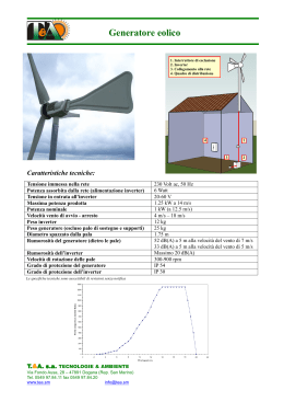
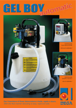
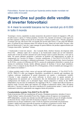
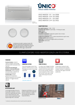
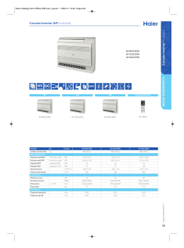
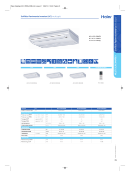
PUMP INVERTER
IT VARIATORE
ELETTRONICO
DI FREQUENZA
DGFLOW srl
Via Emilia, 5 - 46030 Bigarello (Mantova) Italy
tel. +39 0376 340922 - fax. +39 0376 249525
[email protected] - www.dgflow.it
EN VARIABLE
FREQUENCY DRIVE
Made in Italy by
10011707A
2
IT INDICE
EN INDEX
Norme di sicurezza
Safety Standards
Pag. 4
Descrizione del prodotto
Product description
Pag. 5
- Generalità
- General remarks
- Codice di identificazione del prodotto
- Product identification code
- Applicazione in parallelo con altri inverter
- Parallel applications with other inverters
- Dati tecnici generali
Campo lavoro e parametri funzionamento
- General technical data
Range and Operational Parameters
- Parametri di base
- Basic Parameters
- Parametri avanzati
- Advanced Parameters
- Requisiti EMC
- EMC requirements
- Condizioni operative e limiti di impiego
- Operational conditions and working limits
- Dimensionamento serbatoio autoclave
Pag. 7
- Surge tank dimensioning
Dimensioni e pesi
Dimensions and weights
Pag. 11
Installazione
Installation
Pag. 11
- Controlli preliminari
- Preliminary checks
- Collegamento idraulico
- Hydraulic connection
- Collegamento elettrico
- Electric connection
- Adescamento
- Priming
Configurazione dei parametri
Parameters configuration
Pag. 15
- Descrizione della tastiera
- Description of the keyboard
- Configurazione parametri principali (SET1)
- Main parameters configuration (SET1)
- Configurazione parametri avanzati (SET2)
- Advanced parameters configuration (SET2)
- Impostazioni di fabbrica
Prima messa in marcia
- Factory settings
Starting up
- Accensione
- Start-up
- Test
- Test
- Funzionam. normale (NORMAL MODE)
- Normal functioning (NORMAL MODE)
Manutenzione
Maintenance
- Allarmi
- Alarms
- Messa fuori servizio
- Put out of service
- Ricerca guasti
- Troubleshooting
- Cablaggi e Connessioni
- Wiring and Connections
- Garanzia
Pag. 24
Pag. 30
- Warranty
Smaltimento
Disposal
Pag. 37
Dichiarazione di conformità
Declaration of Conformity
Pag. 37
Esploso ricambi
Spare parts diagram
Pag. 38
3
IT NORME DI SICUREZZA
Istruzioni importanti per la sicurezza.
EN SAFETY STANDARDS
Safety important instructions.
Questo simbolo avverte che la mancata osservanza della prescrizione comporta un rischio di
scosse elettriche.
This symbol warns that failure to comply with
the prescription leads to a risk of electric
shocks.
Questo simbolo avverte che la mancata osservanza della prescrizione comporta un rischio di
danno a persone o cose.
This symbol warns that failure to comply with
the prescription leads to a risk of injury/damage to persons/objects.
Prima di installare e utilizzare il prodotto
leggere attentamente il presente manuale in
tutte le sue parti. L’installazione e la manutenzione
devono essere eseguite da personale qualificato,
responsabile di eseguire i collegamenti idraulici
e elettrici secondo le applicabili norme vigenti. Il
produttore declina ogni responsabilità per danni
derivanti da uso improprio del prodotto e non è
responsabile di danni causati da manutenzioni o
riparazioni eseguite da personale non qualificato
e/o con parti di ricambio non originali. L’utilizzo di
ricambi non originali, manomissioni o usi impropri,
fanno decadere la garanzia sul prodotto.
In fase di prima istallazione
assicurarsi che:
- Non ci sia tensione sulla rete di
alimentazione elettrica;
- La rete di alimentazione elettrica sia dotata
di protezioni e di messa a terra conformi alle
norme.
In caso di manutenzione
assicurarsi che:
- L’impianto non sia in pressione
(aprire un rubinetto);
- Non ci sia tensione sulla rete di
alimentazione elettrica;
- Prima di rimuovere il coperchio dell’inverter
o iniziare interventi su di esso, è necessario
scollegare l’impianto dalla rete elettrica ed
attendere almeno 5 Minuti affinchè i condensatori
del circuito intermedio, che possono raggiungere
tensioni fino ad 800V, abbiano il tempo di scaricarsi mediante i resistori di scarica incorporati.
Before installation and use of the product,
read this manual completely and thoroughly.
Installation and maintenance must be carried out
by qualified staff, responsible for performing the
hydraulic and electric connections according to
the applicable Standards in force. The manufacturer declines all responsibility for damage deriving
from improper use of the product and is not liable
for damage caused by maintenance or repairs that
are carried out by unqualified staff and/or using
non-original spare parts. The use of non-original
spare parts, tampering or improper use, make the
product warranty null and void.
First installation
make sure that:
- the electric power supply network
is not live;
- The electric power supply network is
protected by ground connections in
compliance with the Standards.
When carrying out maintenance
make sure that:
- the plant is not pressurised
(open a tap);
- the electric power supply network
is not live;
- Before removing the inverter cover or starting interventions on it, the system must be
disconnected from the mains electricity and
you must wait for 5 mins until the intermediate
circuit condensers, which can reach voltages of up
to 800V, have the time to discharge via the built-in
discharge resistors.
Arresto di emergenza
Mentre l’inverter è in funzione, è possibile eseguire un arresto di emergenza, premendo il tasto
START/STOP.
Nelle applicazioni con inverter in parallelo è solo
l’inverter MASTER che blocca il sistema; l’arresto
di emergenza si effettua perciò premendo il tasto
START / STOP dell’inverter MASTER. Premendo il
tasto START / STOP di un inverter SLAVE, si ha il
solo effetto di arrestare quell’inverter, e non l’intero
gruppo.
Emergency stop
An emergency stop can be performed while the
inverter is running, by pressing the START/STOP
key.
In installations with parallel inverters only the MASTER inverter blocks the system. An emergency
stop is performed by pressing the START / STOP
switch on the MASTER inverter. If the START /
STOP switch on a SLAVE inverter is pressed the
only effect is that that single inverter is stopped;
not the entire system.
4
IT DESCRIZIONE DEL PRODOTTO
Generalità:
STEADYPRES è un regolatore di velocità alimentato in monofase per elettropompe con motori
elettrici a c.a. monofase e trifase.
• Mantiene costante la pressione di impianto
ad un valore definito dall’utenza, adeguando la
prestazione della pompa alla richiesta istantanea,
tramite variazione del numero di giri del motore.
• Effettua continuamente controlli sui parametri
elettrici e di funzionamento, garantendo la protezione del gruppo di pompaggio da ogni tipo di
comune anomalia (sovracorrenti, marcia a secco,
etc)
• Lavora in configurazione stand-alone oppure
in parallelo con altri inverter tramite connessione
seriale (modulo opzionale).
• Si adatta ad ogni tipologia di impianto, anche
esistente, mentre semplifica la progettazione e
la complessità dei nuovi impianti, riducendone i
costi, poiche evita l’impiego di pressostati, vasi di
espansione importanti, quadri elettrici di controllo,
valvola di ritegno.
• Aziona le elettropompe con rampe di avviamento
a velocità progressiva che limitano le correnti di
spunto, allungando la vita dei motori e consentendo un notevole risparmio energetico.
• Quando lavora in configurazione parallela con
altri inverter, STEADYPRES gestisce l’alternanza
degli avviamenti, per uniformare l’utilizzo della
pompe.
1 - Sistema di controllo
2 - Connettore elettrico estraibile
3 - Passacavi di I/O potenza
4 - Coperchio della scheda di potenza
5 - Giunto in tre pezzi
6 - Targhetta dati tecnici
7 - Interruttore
8 - Fusibile
9 - Gruppo valvola di non ritorno
10 - coperchio della scheda di espansione
EN PRODUCT DESCRIPTION
General remarks:
STEADYPRES is a speed regulator powered in
single-phase for electric a.c. single-phase and
three-phase motors.
• It keeps the system pressure constant at a value
defined by the user, adapting pump performance
to instant request, changing the number of motor
revs.
• It carries out continuous controls on electric and
functioning parameters, saving the pumping unit
from all common anomalies (over-currents, dry
running, etc)
• It works in stand-alone configuration or in parallel
with other inverter via serial connection (optional
module).
• It adapts to all type of systems, even existing,
while it simplifies design and complexity of new
systems, thus reducing costs, because it prevents
the use of pressure switches, important expansion
vessels, electric control boards and non-return
valve.
• It activates the electric pump with starting
ramps at a progressive speed, which limit current
peaks, thus lengthening the life of the motors and
allowing a great energy saving.
• When working in parallel with other inverters,
STEADYPRES controls the alternation of starting
to make the use of the pumps uniform.
1 - Control system
2 - Removable electric connector
3 - I/O power cable bushing
4 - Power board cover
5 - Three-piece joint
6 - Technical data plate
7 - Switch
8 - Fuse
9 - Non-return valve unit
10 - expansion board cover
OUT
5
6
4
10
3
1
5
IN
7
2
8
9
5
Descrizione del prodotto
Product description
IT
EN
Codice di identificazione del prodotto
STEADYPRES viene identificato secondo il seguente codice:
Product identification code
STEADYPRES is identified by the following code:
Famiglia di
prodotto.
Product family.
Alimentazione
Monofase.
Single-phase
power supply.
Opzione/Option:
ST M / T 10
Modello
Uscita/Output
Model
T = trifase/three-phase
M= monofase/single-phase
Applicazione in parallelo con altri inverter
STEADYPRES può essere collegato ad uno o due
inverter in parallelo, per mezzo della Scheda di
espansione, che permette di gestire un segnale
RS485 (ed inoltre un segnale di ingresso ed un
segnale in uscita).
Quando più inverter sono collegati in parallelo, è
necessario che uno di essi svolga la funzione di
MASTER, e controlli completamente gli altri, che
perdono ogni autonomia ed assumono il ruolo
di SLAVE (dalla tastiera di un inverter SLAVE in
funzionamento si possono solo scorrere i parametri “frequenza” e “corrente”, e si può spegnere
l’inverter, qualsiasi altro comando proviene dal
MASTER).
Gli inverter (che non siano già installati su gruppi
DGFLOW) escono di fabbrica in configurazione
STAND ALONE; il settaggio MASTER / SLAVE è
rapido e semplice, ed è descritto dettagliatamente
nel Capitolo “Parametri Avanzati (SET2)”.
Una peculiarità del sistema è che se il master
viene spento, gli slave tornano ad essere
indipendenti e completamente autonomi, e
questo aspetto risulta molto utile nella fase di adescamento dei gruppi di pompaggio con inverter
in parallelo (v. paragrafo “Adescamento”) quando
le pompe devono essere manovrate una ad una,
ed in generale risulta comodo spegnere le altre
pompe e poter operare indipendentemente su una
particolare pompa.
Anche in caso di fermata, programmata o
accidentale, dell’inverter MASTER, il fatto che gli
SLAVE funzionino in modo indipendente permette
che il gruppo continui a funzionare regolarmente;
la fermata di uno SLAVE non modifica il comportamento del sistema; il MASTER lavorerà regolarmente con lo SLAVE rimanente.
Modelli con funzionamento a due voltaggi.
I modelli di STEADYPRES contrassegnati da
suffisso “D” possono lavorare indifferentemente a
115V o 230V (Dual Voltage), senza alcuna modifica o programmazione del software.
6
D
Dual voltage
Opzione/Option:
P
Modello/Model
P = Parallelabile
Parallelable
E = Espandibile
Expandable
Parallel applications with other inverters
STEADYPRES can be connected in parallel with
one or two inverters using the expansion board,
which allows it to manage an RS485 signal (as
well as an input and output signal).
When more than one inverter is connected in
parallel, one must be the MASTER with complete
control over the others, which loose their autonomy and become SLAVES. From the keypad of
an operating SLAVE inverter only the “frequency”
and “current” parameters can be scrolled through
and the inverter can be turned off. All other commands come from the MASTER.
The inverters (not already installed on DGFLOW
units) exit the factory in STAND ALONE configuration. The MASTER/SLAVE setup is quick and
simple, and is described in detail in the chapter
“Advanced Parameters (SET2)”.
One feature of the system is that if the master is
turned off the slaves return to being independent
and fully self-governing. This is very useful when
priming the pump units with the inverters in parallel
(see “Priming”). In this phase the pumps must be
controlled one at a time and, in general, it is beneficial to turn off the other pumps in order to focus
on one specific pump.
Even during shutdown, planned or accidental, of
the MASTER inverter, the fact that the SLAVES
operate independently allows the unit to continue
to function normally. If one of the SLAVES stops,
it does not effect the behavior of the system. The
MASTER operates normally with the remaining
SLAVES.
Models with two voltage operation.
The STEADYPRES models with a “D” suffix can
operate at either 115 V or 230 V without distinction (Dual Voltage), without any changes to or
programming of the software.
Campo di lavoro e parametri di funzionamento
Work range and functioning parameters
Dati tecnici generali
- Tensione di alimentaz. 230-115Vac monofase.
- Frequenza 50-60 hz
- Grado di protezione IP65
- Pressione max di esercizio: 10 bar (140 p.s.i.)
- Posizione di lavoro: in qualsiasi posizione; si
consiglia di installarlo nella posizione normale
(ingresso del liquido dal basso, uscita dall’alto)
per poter agevolmente leggere il display ed
utilizzare la tastiera.
- Per tutti i restanti dati tecnici specifici di
ogni modello, fare riferimento alla scheda
tecnica allegata ad ogni inverter.
- Per le condizioni operative ed i limiti di
impiego, fare riferimento al capitolo relativo, in questo manuale.
General technical data
- 230-115Vac power supply voltage.
- Frequency 50-60 hz
- IP65 protection rating
- Maximum working pressure: 10 bar (140 p.s.i.)
- Work position: in any position. It is recommended to install it in a normal position (liquid inlet
from below, outlet from above) in order to read
the display easily and use the keyboard.
- For the remaining specific technical data
of every model, refer to the technical sheet
attached to every inverter.
- For the operational conditions and limits
for use, refer to the relative chapter in this
manual.
IT
EN
CAMPO DI LAVORO E
PARAMETRI DI FUNZIONAMENTO
STEADYPRES mantiene costante la pressione di
impianto (ad un valore definito dall’utenza) al variare della portata richiesta, adeguando la prestazione della pompa tramite variazione del numero
di giri del motore elettrico. Il dimensionamento
dei passaggi idraulici interni e la cura del disegno
idraulico permettono all’inverter
di elaborare portate sino a 200 l/
min con perdite di carico molto
contenute .
Per ottimizzare i risultati in
termini di utilizzo della pompa,
servizio all’utenza e risparmio di
energia, devono essere correttamente dimensionati sia la pompa
che l’inverter, oltre ai parametri
principali di funzionamento i quali si suddividono
in: parametri di base e parametri avanzati.
Parametri di base: sono i parametri che è indispensabile impostare in funzione dell’applicazione:
- p: la pressione di funzionamento richiesta
dall’impianto
- A: la corrente nominale del motore dell’elettropompa
- Ro: senso di rotazione della pompa
WORK RANGE
AND FUNCTIONING PARAMETERS
STEADYPRES keeps the system pressure constant (at a value defined by the user) on variation
of the flow rate requested, adapting pump performance, via variation of the number of electric motor revs. The dimensioning of the internal hydraulic
passages and the careful hydraulic design allow
the inverter to elaborate
flow rates up to 200 l/min
with very small pressure
drops
In order to optimise the
results in terms of pump
use, service to the user
and energy saving, both
the pump and inverter
must be correctly dimensioned, as well as the main functioning parameters, which are divided into: basic parameters and
advanced parameters.
Basic Parameters: these are parameters that are
necessary for setting up the application function:
- p: The operating pressure required by the system
- A: The nominal current of the electric pump
motor
- Ro: Direction of rotation of the pump
- 2P seconda pressione di funzionamento richiesta
dall’impianto (alternativa a “p”). Il parametro 2P
appare quando si attiva l’ingresso ausiliario (vedi
cap. Configurazione dei parametri).
- 2P: second operating pressure required by the
system (alternative to “p”). The 2P parameter
appears only when the auxiliary input is activated
(see Para. Parameter Configuration).
La descrizione della logica, dei limiti e dei valori
suggeriti per questi parametri sono al Cap. “Parametri Principali (SET 1).
The description of the logic, the limits, and the
recommended values are found in Para. “Main
Parameters (SET 1)”.
Parametri avanzati: sono i parametri che
Advanced Parameters: these are parameters
7
Campo di lavoro e parametri di funzionamento
Work range and functioning parameters
IT
EN
perfezionano il funzionamento e richiedono una
conoscenza approfondita del sistema:
- d differenziale di intervento
that fine-tune the operation of the inverter and
require in depth knowledge for proper
application of the system:
- d intervention differential
- LF lowest work frequency
- HF highest work frequency
- Td operating time under dry running
conditions.
- Tp time interval between the automatic attempts
to reset following faults in dry running
- Tf stop delay time for the pump from when no
flow is detected
- RF dynamic reaction of the inerter (quick or slow
response)
- Fs switching frequency
- US “unlock” function: Activates the pump periodically to avoid that the rotating parts grip
- EI setting of the auxiliary input function
- EO setting of the auxiliary relay output
- AF “antifreeze” function: activates the pump
periodically to avoid that the liquid freezes. The
AF parameter appears only when the EO auxiliary
input is activated (see Para. Parameter Configuration).
- W address of the inverter assembled with other
inverters (MASTER or SLAVE)
- LF frequenza minima di lavoro
- HF frequenza massima di lavoro
- Td tempo di funzionamento in condizioni di
”dry running”, ossia in marcia a secco.
- Tp intervallo di tempo tra due tentativi automatici
di ripristino dopo anomalia di “dry running”
- Tf ritardo all’arresto della pompa dal rilievo di
assenza di flusso
- RF reazione dinamica dell’inverter (risposta
rapida o lenta)
- Fs frequenza di switching
- US funzione “unlock”: attiva la pompa periodicamente per evitare il bloccaggio delle parti rotanti
- EI settaggio della funzionalità dell’ingresso
ausiliario
- EO settaggio della funzionalità dell’uscita a relè
- AF funzione “antifreeze”: attiva la pompa periodicamente per evitare il congelamento del liquido.
Il parametro AF appare quando si attiva l’uscita
ausiliaria EO (v. cap. Configurazione dei parametri)
- W indirizzo dell’inverter in batteria con altri inverter (MASTER o SLAVE)
HF
+
HF
Curva della pompa alla
frequenza nominale HF
Pump curve at the nominal HF frequency
FO
Curva della pompa alla
frequenza FO
Pump curve at the FO
frequency
FO
Pset
-
LF
LF
Q min = 2 l/min
Curva della pompa alla
frequenza minima LF
Pump curve at the LF
frequency
- SET. F ripristino set di fabbrica
La descrizione della logica, dei limiti e dei valori
suggeriti per questi parametri sono al Cap. “Parametri Avanzati” (SET 2).
- SET. F restore factory settings
The description of the logic, the limits, and the recommended values are found in Para. “Advanced
Parameters (SET 2)”.
Introdotti i parametri di funzionamento e con
riferimento al grafico sopra, si possono illustrare i
concetti di ottimizzazione del campo di lavoro.
Considerando che la pompa lavorerà a frequenze
comprese tra la frequenza max (HF) e la frequenza di lavoro alla portata nulla (F0):
• HF può essere selezionata nei parametri avanzati, e normalmente è pari a 50 oppure a 60 Hz.
Once the operating parameters are entered, and
referring to the figure above, the concepts for
range optimization can be described.
Considering that the pump will work at a frequency
that falls between the High Frequency (HF) and the
operating frequency at zero flow (F0):
• HF can be selected in the advanced parameters
and is usually equal to 50 or 60 Hz.
8
Campo di lavoro e parametri di funzionamento
Work range and functioning parameters
IT
EN
• F0 non è un parametro selezionabile in modo
indipendente, poiché il suo valore dipende dalla
curva caratteristica della pompa e dal valore impostato come pressione di funzionamento Pset.
• F0 is not an parameter that can be selected independently. Its value depends on the pump curve
and the value set for the operating pressure Pset.
Un corretto accoppiamento inverter / pompa deve
garantire:
- che F0 sia superiore alla minima frequenza di
lavoro (LF); se così non fosse, alle basse portate la
pressione risulterebbe sempre superiore alla Pset
impostata. In questo caso, modificare il valore di
LF accedendo ai Parametri avanzati.
- che F0 risulti di almeno 10 Hz inferiore ad HF; se
così non fosse non vi sarebbe alcun problema di
funzionamento, ma il risparmio energetico risulterebbe poco significativo.
- che alla Pset la pompa, funzionante alla frequenza HF, fornisca una portata prossima alla portata
massima (e quindi normalmente superiore alla
portata di massimo rendimento); se così non fosse
non vi sarebbe alcun problema di funzionamento, ma il risparmio energetico risulterebbe poco
significativo.
A proper inverter / pump connection must guarantee:
- That F0 is greater than the minimum operating
frequency (LF). If this is not the case, the pressure
will always be greater than the Pset set at low flow
rates. In this case, change the LF value using the
Advanced Parameters.
- That F0 is at least 10 Hz less than HF. If this were
not true, there would be no operative problems
but energy savings would be minimal.
- That at Pset, the pump, operating at the HF
frequency, supplies a flow rate close to that of the
maximum flow rate (and therefore normally greater
than the maximum yield flow rate). If this is not the
case, there would not be any operation problems,
but the energy savings would be very slim.
Requisiti EMC
EMC requirements
I requisiti di compatibilità elettromagnetica (EMC)
rispondono alla Direttiva 2004/108/CE (EMC) ed
alle norme armonizzate di riferimento per ambienti
residenziali e industriali.
The electromagnetic compatibility requirements
(EMC) comply with Directive 2004/108/CE (EMC)
and harmonised reference Standards for residential and industrial environments.
Condizioni operative e limiti di impiego
Operational conditions and limits of use
• Fluidi ammessi: gli inverter STEADYPRES sono
utilizzabili con acqua pulita e liquidi chimicamente
non aggressivi ; il loro utilizzo e’ subordinato alle
direttive e legislazioni locali.
Se nel liquido sono presenti impurità, installare un
filtro a monte.
• Pericolo di incendio/esplosione: gli inverter
STEADYPRES non sono adatti al pompaggio di
liquidi infiammabili o ad operare in ambienti con
pericolo di esplosione.
• Limiti di Esercizio:
Pressione massima di esercizio: 10 bar (140 p.s.i.)
Temperatura massima del liquido ammessa dalla
normativa EN60335-2-41: +35°C
Temperatura massima del liquido ammessa dai
materiali: +50°C
Temperatura ambiente massima: +40°C
Variazione di tensione di alimentazione ammessa:
+/- 10% rispetto ai dati di targa.
• Fluids accepted: the STEADYPRES inverter
can be used with clean water and non-aggressive
chemical liquids. Their use is subject to the local
legislation and Directives.
If there are impurities inside the liquid, install a filter
upstream.
• Fire/explosion hazard: the STEADYPRES
inverter is not suitable for pumping inflammable
liquids or for use in environments with risk of
explosion.
• Working Limits:
Maximum working pressure: 10 bar (140 p.s.i.)
Maximum liquid temperature accepted by the
EN60335-2-41 Standard: +35°C
Maximum liquid temperature accepted by the
materials: +50°C
Maximum environment temperature: +40°C
Accepted power supply voltage variation:
+/- 10% with respect to plate data.
Dimensionamento del serbatoio autoclave
Dimensioning of the surge tank
i serbatoi autoclave fungono da accumulo di
acqua in pressione, per evitare che ogni (anche
the surge tanks act as a pressurised water accumulators, to prevent that every user request (also
9
Campo di lavoro e parametri di funzionamento
IT
minima) richiesta dell’utenza, si trasformi nell’avviamento delle pompe.
Svolgono inoltre l’importantissima funzione di
assorbire eventuali colpi d’ariete (sovrapressioni) provenienti dall’impianto, a causa di
manovre brusche, arresti improvvisi, ecc..; in
queste condizioni, le sovrapressioni raggiungono facilmente picchi di alcune decine di bar
(anche se per periodi brevissimi), e possono
danneggiare l’impianto ed anche la struttura
meccanica dell’inverter.
Per questo motivo,
un ammortizzatore deve essere obbligatoriamente previsto.
Il principio di funzionamento dell’inverter permette una notevolissima riduzione
del volume totale dei serbatoi autoclave,
poiché il controllo fa coincidere la prestazione della pompa o del gruppo con la richiesta
dell’utenza.
In condizioni di funzionamento controllato da inverter, ed utilizzando serbatoi a membrana, è sufficiente un volume totale del serbatoio, espresso
in litri, non inferiore al 10% della portata massima
della singola pompa espressa in litri/min.
Ad esempio, una pompa che abbia portata massima di 80 l/min ed un’applicazione standard, necessita indicativamente di un serbatoio di volume:
Vt = 80 x 10% = 8 litri
Il valore risultante deve essere arrotondato per
eccesso alla più vicina taglia commerciale.
10
Work range and functioning parameters
EN
minimum) is transformed into pumps start-up.
They also perform the very important function of absorbing any hammering (overpressure) coming from the system due to
sudden manoeuvres, unexpected stops,
etc.....In these conditions the over-pressures
easily reach peaks of several tens of bar.
(even if for brief periods) and can damage the
system and also the mechanical structure of
the inverter.
For this reason,
a shock absorber must be provided.
The functioning principle of the inverter
allows an important reduction of the total
volume of the surge tanks, because the control makes the pump or unit performance
coincide with the user’s request.
In working conditions controlled by the inverter,
and using membrane tanks, a total tank volume
of 10% of the maximum flow rate of the individual
pump (expressed in litres/min) is sufficient.
For example, a pump with a maximum flow rate
of 80l/min and standard application, requires a
tank with volume of:
Vt = 80 x 10% = 8 litres
The resulting value must be rounded up to the
nearest size on the market.
IT DIMENSIONI E PESI
EN DIMENSIONS AND WEIGHTS
Peso dell’inverter, inclusi 2 giunti in 3 pezzi di
collegamento: 2,9 kg
Weight of the inverter, including 2 3-piece connection joints: 2.9 kg
Dimensioni dell’imballo A x B x H:
310 x 200 x 225 mm
Dimensions of the packaging A x B x H:
310 x 200 x 225 mm
Dimensioni dell’inverter: v. disegno sotto.
Dimensions of the inverter: see drawing below.
IT INSTALLAZIONE
EN INSTALLATION
Prima di installare ed utilizzare STEADYPRES,
leggere attentamente il presente Manuale in
tutte le sue parti e riferirsi alle norme di sicurezza
descritte a pag. 4.
Controlli preliminari:
estrarre il prodotto dall’imballo e controllare:
• che non abbia subito danni,
• che i dati di targa siano quelli desiderati ed
adeguati all’impianto,
• che siano presenti tutti i componenti elencati nel
presente Manuale,
• che le bocche di ingresso ed uscita dell’inverter
siano pulite e libere da eventuali residui del materiale di imballo.
Before installing and using STEADYPRES,
read this manual thoroughly and carefully and
refer to the Safety Standards described
on page 4.
Preliminary controls:
remove the product from the packaging and
control:
- that it has not undergone damage
• that the plate data is that required and suitable
for the system,
• that all components listed in this manual are
present
• that the inverter inlet and outlet are clean and
free from packaging material residues.
L’inverter deve essere installato rispettando le
seguenti condizioni:
- in un locale protetto dalle intemperie e dall’esposizione al sole,
- nelle vicinanze della pompa,
- non deve ricevere vibrazioni nocive dall’ambiente
o dagli apparecchi installati sul circuito,
- non deve ricevere sforzi meccanici dalle tubazioni
collegate.
The inverter must be installed under the following
conditions:
- In a room protected from the weather and from
exposure to sunlight
- Near the pump,
- There can be no harmful vibrations from the
surroundings or from the equipment installed in
the circuit.
- There can be no mechanical stresses due to the
connected piping.
11
Installazione
Installation
IT
EN
Collegamento idraulico.
Hydraulic connection.
l’installazione deve essere effettuata da installatori
competenti ed autorizzati.
Durante l’installazione applicare tutte le disposizioni di sicurezza emanate dagli organi competenti e
dettate dal buon senso.
Installare l’inverter in luogo asciutto e ben ventilato
utilizzando il giunto in tre pezzi (in dotazione) per
il collegamento rapido e sicuro all’impianto (vedi
pag. 5).
installation must be performed by skilled and
authorised installers.
During installation, apply all safety behaviours
suggested by law and common sense.
Install the inverter in a dry, well-ventilated place
using the three-piece joint (supplied) for quick
and safe coupling to the system (see page 5).
Nota: NON applicare sigillanti all’interno del
giunto in 3 pezzi perchè è già provvisto di
o-ring interno di tenuta.
Note: DO NOT apply sealant inside the 3-piece
joint because it already has an internal o-ring.
L’inverter può lavorare in qualsiasi posizione,
anche capovolto (è però sconsigliabile perché la
programmazione e la lettura dei parametri risulterebbero scomodi); in funzionamento non dovranno
verificarsi vibrazioni.
The inverter can work in any position, also upsidedown (however not recommended because the
programming and the reading of the parameters
would be uncomfortable). Vibrations must not
occur during functioning.
Collegamento elettrico.
Electric connection.
• Collegamento alla linea di alimentazione
monofase.
• Connection to the single-phase power
supply line.
Prima di effettuare i collegamenti assicurarsi
che non vi sia tensione ai capi dei conduttori
di linea. Assicurarsi inoltre che la rete di
alimentazione elettrica sia dotata di protezioni
ed in particolare di interruttore differenziale ad
alta sensibilità (30 mA, in classe A oppure AS)
e di messa a terra conformi alle norme.
Before making the connections, make certain
that the ends of the wires are not live. Also make
certain that the electric power network is equipped
with safeties, in particular highly sensitive differential circuit breakers (30 mA, in Class A or AS),
and with ground connections in compliance with
current regulations.
La tensione della linea di
alimentazione dell’inverter potrà
variare in un range compreso
tra il +/-10% della tensione di
alimentazione di targa. Il Cavo
di alimentazione dovrà essere a
3 conduttori (2 fasi + Terra), la
sezione del Cavo da utilizzare,
per una lunghezza della linea
fino a 30m, dovrà essere di
almeno 2,5mm2.
Il collegamento alla linea di alimentazione andrà
effettuato sui morsetti L, N e GND dell’inverter
(vedi figura).
The inverter power supply line
voltage can vary in a range
between +/-10% of the plate
power supply voltage. The
power supply cable must have
3 wires (2 phase + ground), the
section of the cable to use, for
line length up to 30 m, must be
at least 2.5mm2.
The connection to the power
supply line will be performed on the L, N and GND
clamps of the inverter (see figure).
• Collegamento all’elettropompa.
Versione con Inverter alimentato in monofase
con pompa trifase.
Controllare che la corrente nominale assorbita dal
motore sia compatibile con i dati di targa dell’inverter. La tensione di alimentazione del motore
dell’elettropompa installata deve essere 230V
12
• Connection to the electric pump.
Version with inverter powered in single-phase
with three-phase output.
Check that the nominal current absorbed by the
motor is compatible with the inverter plate data.
The power supply voltage of the electric motor,
must be 230V three-phase. The connection
cable between inverter and electric pump must be
Installazione
Installation
IT
EN
Trifase. Il Cavo di connessione
tra inverter ed elettropompa
dovrà essere schermato a 4
conduttori (3 fasi + Terra), la
sezione del Cavo da utilizzare, dovrà essere di almeno
1,5mm2. Il collegamento
tra inverter e motore andrà
effettuato sui morsetti U, V, W
e GND dell’inverter secondo
lo schema. Il collegamento tra
motore e inverter dovrà rispettare la normativa sulla compatibilità EMC.
• Collegamento all’elettropompa.
Versione con Inverter alimentato in monofase
con pompa monofase.
Controllare che la corrente
nominale assorbita dal motore
sia compatibile con i dati di
targa dell’inverter. La tensione
di alimentazione del motore
dell’elettropompa installata
deve essere 230V Monofase. Il Cavo di connessione tra
inverter ed elettropompa dovrà
essere schermato a 3 conduttori (2 fasi + Terra),
la sezione del Cavo da utilizzare, dovrà essere di
almeno 2,5mm2.
Il collegamento tra inverter e motore andrà
effettuato sui morsetti U, V e GND dell’inverter
secondo lo schema.
Il collegamento tra motore e inverter dovrà rispettare la normativa sulla compatibilità EMC.
• Collegamento dei segnali.
La scheda di espansione, situata nella parte
posteriore dell’inverter, contiene i morsetti di collegamento dei segnali (vedi figura sotto).
shielded with 4 wires (3 phases
+ ground), the section of the
cable to be used must be at
least 1.5mm2. The connection
between the inverter and motor
will be performed on the U, V,
W and GND clamps of the inverter, according to the layout.
The connection between motor
and inverter must respect the
Standard regarding EMC.
• Connection to the electric pump.
Version with inverter powered in single-phase
with single-phase output.
Check that the nominal current absorbed by the
motor is compatible with the
inverter plate data. The power
supply voltage of the electric
motor, must be 230V Singlephase. The connection cable
between inverter and electric
L
N
pump must be shielded with 3
wires (2 phases + ground), the
section of the cable to be used
must be at least 2.5mm2.
The connection between the inverter and motor
will be performed on the U, V and GND clamps of
the inverter, according to the layout. The connection between motor and inverter must respect the
Standard regarding EMC.
• Signal Connections.
The expansion board, located in the back of the
inverter, holds the signal connection terminal clamps (see the figure below).
a) Segnale RS485: per la comunicazione tra gli
10
9
8
7
6
5
4
3
2
1
IT Descrizione funzione
morsetti:
10) comune Rs 485
9) Tx+/D+
8) Tx- /D7) Rx6) Rx+
5) Ingresso Livello
4) Gnd
3) NC (Relè Uscita Allarme)
2) N (Relè Uscita Allarme)
1) NO (Relè Uscita Allarme)
EN Terminal clamp operation description:
10) common RS 485
9) Tx+/D+
8) Tx- /D7) Rx6) Rx+
5) Level input
4) Gnd
3) NC (Alarm Output Relay)
2) N (Alarm Output Relay)
1) NO (Alarm Output Relay)
13
Installazione
Installation
IT
EN
inverter o tra inverter e quadro; sono i contatti
indicati alle posizioni 6,7,8,9 e 10.
b) Uscita segnale di allarme: segnala l’eventuale stato di fermo per anomalia; il segnale è
collegabile sia con logica NC sia con logica NO; il
carico massimo collegabile è 5A a 250 VAC; sono
i contatti indicati alle posizioni 1,2 e 3.
c) Ingresso segnale di livello (o altro segnale in
ingresso): permette il collegamento di un sensore
di livello che inibisce il funzionamento se il segnale
non è attivo. Il sensore di livello da collegare dovrà
fornire un contatto ON/OFF; sono i contatti indicati
alle posizioni 4 e 5.
a) RS485 signal: to communicate between inverters or between the inverters and the panel. These
the contacts shown in points 6, 7, 8, 9, and 10.
b) Alarm signal output: signals if there is a stop
due to a fault. The signal can be connected to
both NC and NO control. The maximum load
for connection is 5A at 250 V AC. These are the
contacts shown in positions 1, 2, and 3.
c) Level signal input (or other input signal):
This allows a level sensor to b connected which
stops operation if the signal is not active. The level
sensor connected must provide an ON/OFF contact. These are the contacts shown in positions 4
and 5.
a) Collegamento del segnale tra gli inverter
(segnale RS485). Con riferimento alla figura sopra,
procedere nel seguente modo:
- collegare tra loro i morsetti 9 dei diversi inverter
- collegare tra loro i morsetti 8 dei diversi inverter
Il cavo di segnale dovrà essere a 2 conduttori e la
sezione minima del cavo da utilizzare di 0,5 mm2.
La distanza massima tra gli inverter collegati in
parallelo non dovrà superare i 10 m.
b) Collegamento del segnale di allarme
(dall’inverter MASTER). Con riferimento alla figura
sopra, i morsetti da collegare con il cavo di segnale (a 2 conduttori e sezione minima di 0,5 mm2) il
sono il 2 ed il 3 per funzionamento NC, il 2 e l’1
per funzionamento NO.
c) Collegamento del segnale di livello o altro
segnale in ingresso (dall’inverter MASTER). Con
riferimento alla figura sopra, i morsetti da collegare
con il cavo di segnale (a 2 conduttori e sezione
minima di 0,5 mm2 ) sono il 5 ed il 4.
a) Connection of signal between inverters
(RS485 signal). With reference to the figure shown
above, proceed in the following manner:
- Connect terminal 9 of the inverters together
- Connect terminal 8 of the inverters together
The signal wire must have 2 conductors and the
minimum wire cross-section is 0.5 mm2. The
maximum distance between inverters connected
together in parallel must not be greater than 10 m.
b) Connection of the Alarm Signal
(from the MASTER inverter). Referring to the figure
shown above, the terminals to be connected with
the signal wire (two conductions, minimum crosssection 0.5 mm2) are 2 and 3 for NC operation,
and 2 and 1 for NO operation.
c) Connection of level sensor or other input
signal (from the MASTER inverter). Referring to the
figure shown above, the terminals to be connected
with the signal wire (two conductions, minimum
cross-section 0.5 mm2) are 5 and 4.
Adescamento
Priming
Un sistema di pompaggio non può per alcun motivo essere avviato a secco; il funzionamento a
secco delle pompe, anche per brevissimi periodi,
causa danni irreversibili alla tenuta meccanica ed
agli accoppiamenti rotanti interni.
Prima dell’avviamento del sistema è indispensabile effettuare l’adescamento di tutte le pompe,
svitando il tappo di riempimento e riempiendo
d’acqua il corpo pompa (e la tubazione di aspirazione ad esso collegata); ad operazione completata, riavvitare il tappo e far partire la pompa,
con la valvola di intercettazione in mandata quasi
completamente chiusa, con il sistema in modalità
di funzionamento manuale (TEST).
A pumping system must never be started dry for
any reason. Dry running of the pumps, even for
very brief periods, can cause irreversible damage to mechanical sealing and internal rotating
couplings.
All pumps must be primed before starting the
system by unscrewing the filler cap and filling
the pump body with water (and the intake piping
connected to it). When the operation has been
completed, tighten the cap and start the pump,
with the cut-off valve in flow almost completely
closed, with the system in manual functioning
mode (TEST).
Se dopo poche decine di secondi la pompa non
si fosse adescata, spegnerla, verificare che l’aspirazione sia libera, che non vi siano sacche d’aria
14
If, after a few tens of seconds, the pump is not
primed, switch it off, check that the intake is free,
that there are no air pockets upstream from the
inlet, that the body is full of water and then repeat
the operation.
Configurazione dei parametri
Configuration of the parameters
IT
EN
a monte dell’imbocco, che il corpo sia pieno di
acqua, e ripetere l’operazione.
In the units, priming is performed for each individual pump, turning off the other pumps and performing the operations described above for each
pump. To make priming of each pump simpler,
STEADYPRES suspends the SLAVE operation
if the MASTER is off (that is, the inverter returns
to being completely independent) so that each
inverter can be maneuvered independently during
the priming or test phase.
Once all of the pumps are primed, the operative
parameters can be set on the MASTER inverter
(see Para. “Main Parameters (SET1) and Advanced Parameters (SET 2)) . These are automatically
sent to the SLAVE inverters when they are turned
on.
Nei gruppi, l’adescamento avviene per pompa singola, spegnendo tutte le altre pompe ed
effettuando le operazioni sopra descritte per ogni
pompa. Per rendere semplice l’adescamento di
ogni pompa, STEADYPRES sospende la funzione
di SLAVE se il MASTER è spento (ossia l’inverter
torna ad essere completamente autonomo), in
modo che ogni inverter possa essere manovrato
autonomamente durante la fase di adescamento
o test.
Una volta adescate tutte le pompe, è possibile
settare i parametri di funzionamento sull’inverter
MASTER (v. Parametri Principali (SET 1) e Parametri Avanzati (SET 2) ) e questi saranno automaticamente inviati agli inverter SLAVE, quando saranno
accesi.
IT CONFIGURAZIONE
EN CONFIGURATION
DEI PARAMETRI
OF THE PARAMETERS
Descrizione della tastiera
STEADYPRES è provvisto di tastiera e display che
fungono da interfaccia utente e permettono il controllo dei parametri di funzionamento, degli allarmi
e la programmazione del sistema.
Description of the keyboard
STEADYPRES has a keyboard and display that
act as a user interface and allow to control the
functioning parameters and alarms and also
system programming.
1 - Pulsante accensione/spegnimento
2 - Spia luminosa rossa di messa in rete
3 - Spia luminosa verde di marcia
4 - Display
5 - Pulsante di Test/Set
6 - Pulsante di conferma
7 - Frecce di scorrimento
8 - Impostazione Parametri
1 - On/off button
2 - Luminous red voltage present indicator
3 - Luminous green start indicator
4 - Display
5 - Test/Set button
6 - Confirm button
7 - Scrolling arrows
8 - Setting Parameters
8
7
1
2
3
4
5
6
15
Configurazione dei parametri
Configuration of the parameters
IT
EN
Parametri Principali (SET1)
Main Parameters (SET1)
A partire dal FUNZIONAMENTO NORMALE o dal
FUORI SERVIZIO è possibile entrare in modalità
SET 1 per settare i 3 parametri di base.
Starting from NORMAL FUNCTIONING or from
OUT OF SERVICE, it is possible to enter SET 1
mode to set the 3 basic parameters.
P - pressione di funzionamento richiesta dall’impianto (pressione di settaggio); ha limiti da 1 a
9 bar (15 ÷ 130 p.s.i.) con passo di 0,1 bar (1,5
p.s.i.).
A - corrente nominale di targa del motore: serve
per caratterizzare i parametri di funzionamento
dell’inverter (comprese le sovracorrenti ammissibili)
sulla tipologia di motore utilizzato; i limiti variano
a seconda del modello (v. Scheda Tecnica) con
passo di 0,1 A
Ro - senso di rotazione della pompa: permette l’inversione del senso di rotazione in modo
elettronico, senza la necessità di invertire i cavi in
morsettiera.
P – operation pressure required by the line (set-up
pressure). It is limited from 1 to 9 bar (15 ÷ 130
p.s.i.) in steps of 0.1 bar (1,5 p.s.i.).
A – rated current of the motor tag: this is used to
characterize the operational parameters of the inverter (including the allowable overcurrents) on the
type of motor used. The limits vary according to
the model (see the Data Sheet) with 0.1 A steps.
Ro - Direction of rotation of the pump: allows the
direction of rotation of the pump to be inverted
electronically, without the need to invert the wires
in the terminal board.
2P - seconda pressione di funzionamento richiesta
dall’impianto (alternativa a “p”) ha limiti da 1 a 9
bar (15 ÷ 130 p.s.i.) con passo di 0,1 bar (1,5
p.s.i.).Il parametro 2P appare quando si attiva
l’ingresso ausiliario EI (v. cap. Parametri avanzati
SET 2).
2P - second operative pressure required by the
system (alternative to “p”) is limited from 1 to 9 bar
(15 ÷ 130 p.s.i.) in steps of 0.1 bar (1,5 p.s.i.).
The 2P parameter appears only when the EI
auxiliary input is activated (see Para. Advanced
Parameters SET 2).
Attenzione: quando STEADYPRES è fornito
già installato su pompe o gruppi DGFLOW i
valori dei 3 parametri di base sono preimpostati in fabbrica in funzione del tipo di pompa
collegata all’inverter.
Attention: when STEADYPRES is supplied
already installed on pumps or DGFLOW units,
the values of the 3 basic parameters are set
in the factory depending on the type of pump
connected to the inverter.
Segnalazioni visive
Visual signals
Luce spenta
Light off
POWER
STATUS
P X.X
Lampeggio Alternato.
Alternate Flashing.
16
Luce accesa
Light on
E’ in corso il Settaggio dei
parametri principali.
Note: con i tasti Freccia si passa alla visualizzazione degli altri
Parametri. Con i tasti “+“ e “-“
si variano i valori attuali indicati
con il lampeggio.
Luce lampeggiante
Light flashing
Main parameters setting is
in progress.
Notes: use the arrow keys to
display the other parameters.
Use the “+“ and “-“ keys to
vary the current values indicated by flashing.
Configurazione dei parametri
Configuration of the parameters
IT Modifica dei Parametri Principali (SET1)
EN Modification of Main Parameters (SET1)
A partire dal Funzionamento Normale
Starting from Normal Functioning
A partire dal Fuori
Servizio
P 3.1
Premere insieme,
per primo il tasto “-”
Press together, first
the “-” key
P 3.4
P 3.6
P 3.7
A 7.5
Change
Parameter
P 3.8
A 8.5
A 8.0
A 7.0
A 9.0
Cambio
parametro
RO
Change
Parameter
A 9.5
RO
RO
RO
RO
Cambio
parametro
Change
Parameter
Il parametro 2P appare quando si attiva l’ingresso
ausiliario.
Seconda
pressione di
funzionamento richiesta
dall’impianto
(alternativa a
“p”).
Flashing indication
to confirm using
“ENTER”
P 3.5
Cambio
parametro
A 6.5
Modifica del
senso di
rotazione.
Modification
of the
direction of
rotation.
SET 1
P 3.3
P 3.2
Modifica della
corrente.
Modification
of the
current.
OFF
+
Indicazione lampeggiante da confermare con “ENTER”
Modifica della
pressione.
Modification
of the
pressure.
2P 2,4
2P 2,5
2P 2,3
Conferma delle modifiche e ritorno allo
stato iniziale
Starting from Out
of Service
Cambio
parametro
Confirmation of the
modifications and
return to initial state
EXIT
The parameter 2P appears when the auxiliary input
is activated.
Second operating pressure
2P 2,6
required by
the system
2P 2,7 (alternative to
“p”).
Change
Parameter
Ritorno al settaggio parametri
Return to setting
parameters
17
Configurazione dei parametri
IT
Parametri Avanzati (SET2)
A partire dal FUNZIONAMENTO NORMALE o dal
FUORI SERVIZIO è possibile entrare in modalità
SET 1 per settare i 3 parametri di base.
- d: differenziale di intervento: determina la condizione di avvio della pompa: es. se d = 0,2 bar (3
p.s.i.) e Pset = 3 bar (43 p.s.i.), la pompa si avvia
quando la pressione dell’impianto scende sotto i
2,8 bar (40 p.s.i.). - LF: limite di frequenza inferiore: limita la frequenza minima alla quale far lavorare
la pompa; i valori limite sono da 25 a 40 Hz con
passo 1 Hz. - HF: frequenza massima di lavoro:
normalmente deve coincidere con la frequenza
di targa della pompa (50/60 Hz), ma è prevista
la possibilità di variazioni in difetto di 5 Hz ed in
eccesso di 3 Hz, per necessità di impianto;
Attenzione: la scelta di eccedere la frequenza
massima è sotto la responsabilità dell’installatore, che deve essere competente e conoscere
le conseguenze di un innalzamento della frequenza massima sui rischi connessi al motore,
alla pompa ed all’impianto elettrico.
- Td: tempo di funzionamento in condizioni di ”dry
running”, ossia in marcia a secco (non c’è rilevamento di flusso né la pressione richiesta è stata
raggiunta). Le pompe autoadescanti possono, in
fase di adescamento, lavorare in assenza di flusso
anche per decine di secondi, mentre per le pompe
non autoadescanti occorre non eccedere con il
periodo di funzionamento a secco, per non creare
danni irreversibili alle parti rotanti interne. Il tempo
di “dry running” impostato in fabbrica è di 10 sec,
per evitare fermate per falsi allarmi. I limiti sono da
0 a 100 sec, con passo di 1 s.
- Tp: intervallo di tempo tra due tentativi automatici di ripristino dopo anomalia di “dry essere
running”; settando Tp a zero si elimina la funzione
di ripartenza automatica, ed il ripristino dovrà
manuale; il settaggio di fabbrica è a 10 min; i limiti
vanno da 0 a 100 min con passo di 1 min.
- Tf: ritardo all’arresto della pompa dal rilievo di
assenza di flusso (raggiunta condizione di impianto, in assenza di prelievo): un ritardo eccessivo
comporta un inutile funzionamento a vuoto ed uno
spreco energetico, un ritardo troppo breve non
permette la perfetta stabilizzazione del sistema;
i limiti sono da 1 a 15 sec, con passo di 1 s, il
settaggio di fabbrica è a 3 s.
- RF: “reaction factor”, è il parametro che sintetizza la reazione dinamica dell’inverter (risposta rapida o lenta); per situazioni non standard (risonanze,
impianti lunghi, ecc.) può essere necessario
spostarsi dal valore di default (4). I limiti vanno da 1
(reazione rallentata) a 5 (reazione rapida).
- FS: frequenza di commutazione: caratterizza
l’onda elettrica in uscita dall’inverter, affinché sia
18
Configuration of the parameters
EN Advanced Parameters (SET2)
A partire dal FUNZIONAMENTO NORMALE o dal
FUORI SERVIZIO è possibile entrare in modalità
SET 1 per settare i 3 parametri di base.
- d: intervention differential: Determines the conditions for starting the pump: For ex. If d = 0.2 bar (3
p.s.i.) and Pset = 3 bar (43 p.s.i.), the pump starts
when the system pressure drops below 2.8 bar
(40 p.s.i.).
- LF: Lower frequency limit: Lower frequency limit
for the pump to operate. The limit values are from
25 to 40 Hz in 1 Hz steps.
- HF: Highest work frequency: Normally this must
coincide with the plate frequency of the pump
(50/60 Hz), but a -5 Hz / +3 Hz variation is allowed
based on the line.
Warning: the choice to have an excess
maximum frequency is the responsibility of
the installer, who must be skilled and know
the consequences of raising the maximum
frequency and the risks related to the motor,
the pump, and the electric system.
- Td: Operative time under dry running conditions
(when flow is not detected, and the pressure
required has been reached). Self-priming pumps
can, during priming, work without flow even for
dozens of seconds, whereas non-self-priming
pumps cannot withstand a prolonged dry running
period in order to avoid creating irreversible
damages to the rotating parts. The dry running
time factory setting is 10 seconds in order to avoid
stops due to false alarms. The limits are from 0 to
100 seconds in steps of 1 s.
- Tp: Time interval between two attempts to automatically reset following a fault during dry running.
By setting Tp to zero the automatic restart function
is eliminated and must be performed manually.
The factory setting is 10 minutes; the limits are
from 0 to 100 minutes in 1 min. steps.
- Tf: Pump stop delay from when no flow detected (at system conditions, without pick-up): A too
long delay means useless dry running and a waste
of energy; a too short delay time does not allow
the system to stabilize. The limits range from 1 to
15 s with 1 s steps. The factory setting is 3 s.
- RF: “Reaction factor” is the parameter that summarizes the dynamic reaction of the inverter (quick
or slow response). For non-standard situations
(resonance, long lines, etc.) it may be necessary to
shift the default value (4). The limits range from 1
(slow reaction) to 4 (quick reaction).
- FS: Switching frequency: Characterizes the
electric wave output by the inverter so that it is
optimized for installations with long wires. This
parameter is programmed based on the length of
Configurazione dei parametri
Configuration of the parameters
IT
EN
ottimizzata nelle applicazioni con cavi lunghi. Si
programma in funzione della lunghezza dei cavi
e sono previste tre condizioni d’onda: HI per cavi
lunghi sino a 5 m, ME per cavi da 5 a 20 m, LO
per cavi oltre i 20 m . il settaggio di fabbrica è HI.
- US: funzione “unlock system” per evitare il bloccaggio della tenuta meccanica o altre parti rotanti
causato da lunghi periodi di inattività; se attivata,
avvia la pompa per 5 s alla frequenza minima impostata, ad intervalli di tempo predefiniti settando
il parametro “US (da 1 a 999 min con passo 10
min); settando US a zero la funzione è disabilitata.
- EI: permette di settare la funzionalità dell’ingresso ausiliario (Morsetti 4-5) posto sulla scheda di
espansione; le funzionalità programmabili sono 0,
1, 2, 3, 11, 12, 13.
the wires and three wave conditions are available:
HI for wires up to 5 m long, ME for wires from 5 to
20 m long, and LO for wires more than 20 m long.
The factory setting is HI.
- US: “Unlock system” function to avoid the mechanical seal or other rotating parts from gripping
due to long periods of no activity. If activated, it
starts the pump for 5 s at the minimum frequency
set, at the time intervals set using the “US” parameter (from 1 to 99 min in 10 min steps. When set
to zero this function is disabled.
- EI: Allows the auxiliary input function on the
expansion board to be set-up (Terminals 4-5).
The programmable functions are 0, 1, 2, 3, 11, 12,
and 13.
0 = Nessuna Funzione: lo stato dell’ingresso viene
ignorato.
1 = Ingresso Segnale di livello. Se il segnale di
livello non è presente L’inverter non parte e segnala
l’allarme “LOW LEVEL” quando è presente il
segnale la scritta scompare e l’inverter torna a
funzionare normalmente.
2 = Avvio & messa fuori servizio mediante segnale
esterno. Se il segnale non è presente l’inverter
non parte e compare la scitta “Ext OFF” quando è
presente il segnale la scritta scompare e l’inverter
torna a funzionare normalmente.
3 = Passaggio a 2° setpoint di pressione. Quando
si attiva l’ingresso, l’inverter legge un secondo
valore di Pset (memorizzato nel parametro 2P del
SET1) e regola in funzione di quello.
11 = stessa funzione di 1 ma con logica NC
12 = stessa funzione di 2 ma con logica NC
13 = stessa funzione di 3 ma con logica NC
0 = No Function: The status of the input is ignored.
1 = Level signal input. If the level signal is not
present, the inverter does not start and the “LOW
LEVEL” alarm is triggered. When the signal is
present, the message disappears and the inverter
returns to normal operation.
2 = Start & Out of Service using external signal. If
the signal is not present, the inverter does not start
and the “Ext OFF” alarm is triggered. When the
signal is present, the message disappears and the
inverter returns to normal operation.
3 = Pass to second pressure set point. When the
input is activated the inverter reads a second Pset
value (saved in parameter 2P of SET1) and responds based on it.
11 = same function as 1 but with NC logic
12 = same function as 2 but with NC logic
13 = same function as 3 but with NC logic
Nota: Per attivazione dell’ingresso con logica N.O.
si intende la chiusura del contatto (Ponte), tra i
morsetti 4 e 5 della scheda di espansione.
- EO: Permette di settare la funzionalità dell’uscita
a relè (C-NO-NC Morsetti 1-2-3) posta sulla scheda di espansione, le funzionalità programmabili
sono: 0, 1, 2, 3, 4.
0 = Nessuna Funzione (Il relè non viene mai
attivato)
1 = Uscita di Allarme (livello 1). Il rele si attiva
ogni volta che l’inverter va in allarme (INVERTER
ERROR, OVER CURRENT, HIGHT TEMPERATURE, OVER TEMPERATURE, NO COMUNICATION,
LOW LEVEL, LOW VOLTAGE).
2 = Pompa in funzione.
3 = Funzione Antifreeze. Attiva il rele di uscita ad
intervalli di tempo predefiniti impostati nel parametro “AF” del Set 2.
Nota: Activation of the input with NO logic is the
closure of the contact (Jumper) between terminals
4 and 5 on the expansion board.
- EO: Allows the relay output function on the expansion board to be set-up (C-NO-NC Terminals
1-2-3). The programmable functions are 0, 1, 2,
3, and 4.
0 = No Function (the relay is never activated)
1 = Alarm Output (Level1). The relay activates
each time the inverter goes into alarm (INVERTER
ERROR, OVER CURRENT, HIGH TEMPERATURE,
OVER TEMPERATURE, NO COMMUNICATION,
LOW LEVEL, OR LOW VOLTAGE)
2 = Pump running
3 = Antifreeze Function. Activates the output relay
at the time intervals predefined in parameter “AF”
of SET2.
19
Configurazione dei parametri
Configuration of the parameters
IT
EN
- AF: intervallo di intervento della funzione
“antifreeze”; (v. parametro avanzato EO), i limiti
dell’intervallo di intervento vanno da 1 a 999 min
con passo 10 min.
Il parametro AF appare quando si attiva l’uscita
ausiliaria EO (v. in precedenza).
- AF: time interval for the antifreeze function (see
Advanced Parameter EO). The limits of the interval
for activation range from 1 to 999 min in 10 min
steps.
At AF parameter appears when the EO auxiliary
output is activated (see above).
- W: caratterizza il comportamento dell’inverter
quando è collegato ad altri inverter: può assumere il ruolo di MASTER, SLAVE oppure essere in
STAND ALONE. W prende i seguenti valori: NC
(STAND ALONE), MS (MASTER), S1 (SLAVE 1),
S2 (SLAVE 2).
- W: Defines the behavior of the inverter when
connected to other inverters. It can be either
MASTER, SLAVE or STAND ALONE. W has the
following values: NC (STAND ALONE), MS (MASTER), S1 (SLAVE 1), or S2 (SLAVE 2).
L’assegnazione dell’indirizzo MASTER / SLAVE deve essere effettuata a partire dall’inverter
MASTER, accendendo, settando e spegnendo un
inverter alla volta.
The assignment of the MASTER / SLAVE address
must be performed from the MASTER inverter, turning it on, setting it up and turning off the inverter.
I segnali di ingresso e uscita sono gestiti solo
dall’unità MASTER.
The input and output signals are managed only by
the MASTER units.
- SET. F: ripristino SET di fabbrica: nel caso in
cui le modifiche apportate ai parametri creino
problemi di funzionamento e si intenda ritornare al
settaggio di fabbrica, è possibile farlo rapidamente
con questa funzione.
- SET. F: Reset the factory settings. If the changes
made to the parameters create problems in operation and you want to return to the factory settings,
this can be done quickly using this function.
Attenzione: anche questi parametri, quando STEADY PRES è fornito già installato su pompe o gruppi
DGFLOW, sono preimpostati in fabbrica in funzione
del tipo di pompa collegata all’inverter. Non sarà
pertanto necessario intervenire su questi parametri se
non in caso di particolari situazioni di impianto.
Visual signals
Segnalazioni visive
Luce spenta
Light off
POWER
STATUS
d X.X
Lampeggio Alternato.
Alternate Flashing.
20
Attention: when STEADYPRES is supplied already
installed on pumps or DGFLOW units, also these parameters are set in the factory depending on the type
of pump connected to the inverter. It will therefore
not be necessary to set these parameters, unless in
particular system situations.
Luce accesa
Light on
E’ in corso il Settaggio dei
parametri avanzati (attività
necessaria solo in caso di particolari esigenze d’impianto).
Note: con i tasti Freccia si passa alla visualizzazione degli altri
Parametri. Con i tasti “+“ e “-“
si variano i valori attuali indicati
con il lampeggio.
Luce lampeggiante
Light flashing
Setting of advanced
parameters is in progress
(activity necessary only in
the case of particular system
requirements). Notes: use the
arrow keys to display the other
parameters. Use the “+“ and
“-“ keys to vary the current
values indicated by flashing.
Configurazione dei parametri
Configuration of the parameters
IT Settaggio dei Parametri Avanzati (SET2)
EN Advanced Parameters Setting (SET2)
+
P 3.1
Indicazione lampeggiante da confermare con “ENTER”
d 0.2
LF 26
+
SET 2
OFF
Flashing indication
to confirm using
“ENTER”
d 0.3
d 0.4
d 0.5
LF 27
LF 28
LF 29
d 0.6
LF 30
HF 62
HF 61
HF 52
HF 51
HF 50
+
HF 50
+
HF 60
HF 59
HF 58
HF 49
HF 48
Td 8
Tp 8
Tf 01
RF 1
Fs ME
Td 9
Td 10
Td 11
Tp 9
Tp 10
Tp 11
Tf 02
Tf 03
Tf 04
RF 2
RF 3
RF 4
Fs HI
Fs LO
Fs ME
Continua
Td 12
Tp 12
Tf 05
RF 5
Fs HI
Next page
21
US 980
EI 12
EO 2
AF 980
US 990
US 0
US 10
EI 13
EI 0
EI 1
EO 3
EO 0
EO 1
AF 990
AF 60
AF 10
Il parametro AF appare quando si attiva
l’uscita ausiliaria EO
W S1
W S2
US 20
EI 2
EO 2
AF 20
The AF parameter appears when the EO
auxiliary output is activated.
W NC
SET. F
W MS
W S1
WAIT
3 s.
Premere per 3 secondi
Press for 3 seconds.
Conferma delle modifiche e
ritorno allo stato
iniziale.
Confirmation of the modifications and return to initial
state.
22
EXIT
Ritorno al settaggio
parametri.
Return to setting parameters.
Configuration of the parameters
Configurazione dei parametri
IT
Impostazioni di fabbrica
EN Factory settings
Nel caso di fornitura del solo inverter, i parametri di
base ed avanzati sono settati di fabbrica su valori
medi ottimali per la maggior parte delle applicazioni, in particolare:
SET 1
P
A
Ro
2P
IT
Pressione di funzionamento
If just the inverter is supplied, the basic and advanced parameters are factory set on optimal average
values for most applications, in particular:
EN
Operating Pressure
Corrente nominale di targa
del motore per ST M/T 10 e
ST M/M 10
Corrente nominale di targa
del motore per ST M/T 07 e
ST M/M 07
Corrente nominale di targa
del motore per ST M/M 11
Corrente nominale di targa
del motore per ST M/M 13
Senso di rotazione
Seconda pressione di funzionamento
Nominal plate current of the
motor for ST M/T 10 and ST
M/M 10
Nominal plate current of the
motor for ST M/T 07 and ST
M/M 07
Nominal plate current of the
motor for ST M/T 11
Nominal plate current of the
motor for ST M/T 13
Direction of rotation
Second operating Pressure
Differenziale di ripartenza
Restart differential
SET 2
d
LF
HF
Frequenza minima di lavoro
Frequenza massima di
lavoro (50/60 Hz)
Td
Tempo di Dry Running
Tp
Tempo di attesa per ripartenza dopo Dry Running
Tf
Tempo di attesa per arresto
dopo assenza di flusso
(raggiunta condizione di
impianto)
RF
Reaction Factor
Fs
Frequenza di switching
US
Unlock System (antibloccaggio tenuta meccanica)
EI
Funzione Ingresso (scheda
di espansione)
EO
Funzione Uscita ((scheda di
espansione)
AF
AntiFreeze (funzione antigelo)
W
Configurazione nel collegamento di più dispositivi
Set. F Ripristino SET di fabbrica
Lowest work frequency
Highest work frequency
(50/60 Hz)
Dry running time
Waiting time for restart after
dry running
Waiting time to stop after no
flow (under line conditions)
Reaction Factor
Switching frequency
Unlock System (anti-grip of
mechanical seal)
Input function (expansion
board)
Output function (expansion
board)
Antifreeze function
Configuration for the connection of multiple devices
Reset factory settings.
Nel caso di fornitura dell’inverter montato su
pompa o gruppo DGFLOW, i parametri di base ed
avanzati sono preimpostati in fabbrica in funzione
del tipo di pompa collegata all’inverter e differiscono da quanto sopra esposto.
Default
Min.
Max.
Step
u.m.
3,5
50
1
15
9
130
0,1
1,5
bar
p.s.i.
10
1
12
0,1
A
7
1
7
0,1
A
11
1
13
0,1
A
13
->
2,5
35
1
16
->/<9
130
0,1
0,1
1,5
A
bar
p.s.i.
1
15
Default
Min.
Max.
Step
u.m.
0,2
3
25
0,2
3
25
1
15
40
0,1
1,5
1
bar
p.s.i.
Hz
50/60
10
45/53
0
55/63
100
1
1
Hz
sec
10
0
100
1
min
3
4
HI
1
1
15
5
LO-ME-HI
1
1
sec
-
0
0
990
10
min
0
0-1-2-3-11-12-13
-
0
0-1-2-3
-
60
NC
10
990
10
NC-MS-S1-S2
min
-
If the inverter is supplied installed on a pump or
the DGFLOW unit, the base and advanced parameters are factory pre-set for the type of pump
connected to the inverter and therefore differ from
the information provided herein.
23
IT PRIMA MESSA IN MARCIA
EN STARTING UP
Prima della messa in marcia è indispensabile aver
letto attentamente il presente Manuale e seguire
le istruzioni; si prevengono così impostazioni e manovre errate che potrebbero causare anomalie di
funzionamento. Il sistema non può per alcun
motivo essere avviato a secco; il funzionamento a secco delle pompe, anche per brevissimi periodi, causa danni irreversibili alla tenuta
meccanica ed agli accoppiamenti rotanti interni.
Prima dell’avviamento del sistema è indispensabile
effettuare l’adescamento (v. pag. 14)
Dopo aver eseguito le operazioni descritte nel
Capitolo INSTALLAZIONE è possibile passare
all’accensione dell’inverter.
Before starting up, please read carefully this
Manual and follow the instructions. In this way
incorrect settings and manoeuvres are prevented,
which could cause functioning anomalies. The
system must never be started dry for any
reason. Dry running of the pumps, even for very
brief periods, can cause irreversible damage
to mechanical sealing and internal rotating
couplings.
Priming must be performed before system start-up
(see page 14)
When the operations described in the INSTALLATION chapter have been performed, the inverter
can be started.
Accensione
Quando l’apparecchiatura viene
alimentata dalla rete (alla prima
installazione, dopo uno spegnimento volontario o in caso di
caduta e successivo ritorno della
tensione di rete), entra in una fase di STARTING
della durata di circa 10 secondi, trascorsi i quali
STEADYPRES ritorna nelle stesse
condizioni di funzionamento in
cui era al momento dell’ultimo
spegnimento (anche in caso di caduta accidentale dell’alimentazione),
in quanto tutti i parametri di funzionamento, comprese le condizioni di
allarme o di blocco, vengono memorizzate su una memoria non volatile.
Se all’ultimo spegnimento STEADYPRES era
in condizione di ON, superati i 10
secondi, la pompa si avvia se rileva
una pressione inferiore a quella di
settaggio; è possibile mettere FUORI
SERVIZIO il gruppo, prima del suo avviamento automatico, battendo START
/ STOP. Se all’ultimo spegnimento STEADYPRES
era in condizione di OFF, superati i 10 secondi,
il gruppo entra in FUORI SERVIZIO, per avviarlo
battere START / STOP.
Start-up
Whenever the equipment is powered by the mains (upon initial
installation, following voluntary
shutdown or in the event of a
power cut and the subsequent
return of power), it will enter a START phase
lasting about ten seconds. Because all of the operating parameters - including its alarm/
blocking conditions - are stored on a
non-volatile memory, the STEADYPRES will resume the same operating conditions as when it was last
shut-down (including in the event of
accidental power supply failure) after
this 10-second start phase.
Where the STEADYPRES was ON when the
last shut-down occurred, the pump will activate
after these 10 seconds if the pressure
detected is less than the predetermined
threshold; you can put the group OUT
OF SERVICE prior to the automatic
start-up by hitting START/STOP.
Where the STEADYPRES was OFF
when the last shut-down occurred, the group will
remain OUT OF SERVICE following the10-second
start phase. To start-up, hit START/STOP.
Nelle applicazioni con inverter in parallelo, l’inverter
MASTER controllerà completamente gli inverter
SLAVE, che potranno operare autonomamente
solo se il MASTER è spento.
In ogni gruppo può esserci UN SOLO MASTER,
un solo SLAVE 1 ed un solo SLAVE 2.
24
In parallel inverter installations, the MASTER inverter fully controls the SLAVE inverters, which can
operate independently only when the MASTER is
turned off.
In each unit there can be ONLY ONE MASTER,
one SLAVE 1 and one SLAVE 2.
Prima messa in marcia
Starting up
IT
EN
Segnalazioni visive
Visual signals
Luce spenta
Light off
POWER
STATUS
POWER
STATUS
STA....
Luce accesa
Light on
Luce lampeggiante
Light flashing
Assenza di alimentazione
elettrica.
Il gruppo non è alimentato elettricamente.
No electric power supply.
The unit is not powered electrically.
Avviamento.
Il gruppo è stato alimentato elettricamente da meno di 10 secondi.
Note: viene visualizzato il messaggio “STARTING” a scorrimento per
10 secondi, poi il gruppo ritorna
nella stessa condizione di funzionamento in cui era prima dello
spegnimento.
Start-up.
The unit has been powered electrically for less than 10 seconds.
Notes: the running “STARTING”
message is displayed for 10 seconds and then the unit goes back
to the same functioning condition
as at the time of switch-off.
25
Prima messa in marcia
IT
Starting up
Test
EN Test
A partire dallo stato di FUORI SERStarting from the OUT OF SERVIVIZIO è possibile entrare in modalità
CE status, enter the TEST mode to
TEST per avviare, modulare ed arrestamanually start, modulate and stop the
re manualmente la pompa.
pump.
Utilizzando i tasti “+” e “-” si incremenUsing the “+” and “-” keys, increase or
ta o decrementa di 5 Hz la velocità del motore.
decrease the motor speed by 5 Hz.
Nel contempo si possono verificare i parametri
In the meantime, it is possible to check the paraP (Pressione), A (Assorbimento), F (Frequenza)
meters P (Pressure), A (Absorption), F (Frequency)
utilizzando i tasti di scorrimento.
using the scroll keys.
Dopo 30 secondi di funzionamento in modalità
After 30 seconds of functioning in TEST mode, the
TEST la pompa avviata si arresta AUTOMATICAstarted pump stops AUTOMATICALLY
MENTE
Durante il TEST è possibile verificare il
During the TEST it is possible to
corretto funzionamento del SENSORE
check the correct functioning of the
DI PORTATA integrato nella valvola di
FLOW RATE SENSOR, integrated
non ritorno. Se il sensore rileva una
in the non-return valve. If the sensor
portata SUPERIORE a 2 litri/min viene
Indicatore di flusso. detects a flow rate EXCEEDING 2
visualizzato un trattino sul display.
Flow indicator. litres/min, a hyphen is shown on the
Nel caso di flusso inferiore il trattino
display. If the flow is lower, the hyphen
scompare.
disappears.
OFF
TEST
EXIT
+ 5 = Aumento giri motore
a passi di 5 Hz.
- 5 = Diminuzione giri
motore a passi di 5 Hz.
+ 5 = Increase of motor
revs at steps of 5 Hz.
P ...
- 5 Hz
+ 5 Hz
F ...
- 5 Hz
+ 5 Hz
- 5 = Decrease of motor
revs at steps of 5 Hz.
A ...
- 5 Hz
26
+ 5 Hz
Prima messa in marcia
Starting up
Segnalazioni visive
Visual signals
Luce spenta
Light off
POWER
STATUS
POWER
STATUS
POWER
STATUS
POWER
STATUS
Luce accesa
Light on
Luce lampeggiante
Light flashing
TEST
Il sistema è predisposto per
effettuare il Test di marcia
Manuale della pompa.
La pompa non è in marcia.
Note: il sistema permette di
mettere in marcia la pompa.
The system is set-up to
perform the manual run test
The pump is not running.
Notes: the system allows to
start pump up.
P_X.X
Il Test di marcia Manuale
della pompa è in corso.
Nota: viene visualizzata la
Pressione d’impianto. Il “TRATTINO“ dopo la lettera “P“
indica che il sistema rileva un
flusso superiore a 2 litri/min.
The Manual Test of pump is
in progress.
Note: the plant pressure is
displayed. The “HYPHEN”
after the letter “P” indicates
that the system detects a flow
exceeding 2 litres/min.
A X.X
Il Test di marcia Manuale
della pompa è in corso.
Nota: viene visualizzata la Corrente assorbita dalla pompa in
fase di Test.
The Manual Test of pump is
in progress.
Note: the current absorbed by
the pump in Test is displayed.
F XX.X
Il Test di marcia Manuale
della pompa è in corso.
Nota: viene visualizzata la frequenza di lavoro della pompa
in fase di test.
The Manual Test of pump is
in progress.
Note: the pump work frequency is displayed.
27
Prima messa in marcia
Starting up
IT
EN Normal functioning
Funzionamento Normale
In funzionamento normale è possibile:
• visualizzare la pressione di impianto.
• visualizzare l’assorbimento del
motore (se il motore è in funzione).
• visualizzare la tensione di alimentazione (se il motore è fermo).
• visualizzare la frequenza di lavoro.
• visualizzare eventuali condizioni di allarme della
pompa.
• mettere FUORI SERVIZIO la pompa.
• settare i parametri SET1 e SET2.
Nei gruppi, l’inverter MASTER permette di verificare che gli inverter comunichino correttamente tramite la visualizzazione dello STATO DEL SISTEMA
(v. tabelle seguenti).
Segnalazioni visive
STATUS
POWER
STATUS
POWER
STATUS
POWER
STATUS
POWER
STATUS
POWER
STATUS
POWER
STATUS
28
In units, the MASTER inverter allows you to check
that the inverters communicate correctly using the
SYSTEM STATUS display (see the tables below).
Visual signals
Luce spenta
Light off
POWER
In normal functioning it is possible:
• to display the system pressure
• to display motor absorption (if the
motor is running).
• to display the power supply voltage (if
the motor is not running).
• to display the work frequency.
• to display any pump alarm conditions.
• to put the pump OUT OF SERVICE.
• to set the parameters SET1 and SET2.
Luce accesa
Light on
Luce lampeggiante
Light flashing
P X.X
Pompa ferma.
Nota: viene visualizzata la
pressione d’impianto che risulterà maggiore o uguale della
pressione P di settaggio.
Pump at standstill.
Note: the system pressure is
displayed, which is greater
than or the same as the pump
setting pressure P.
P_X.X
Pompa in marcia.
Nota: viene visualizzata la
pressione d’impianto. La
presenza del “trattino” dopo la
lettera “P” indica che il sistema
rileva un flusso superiore a 2
litri/min.
Pump running.
Note: the plant pressure is
displayed. The presence of
the “hyphen” after the letter
“P” indicates that the system
detects a flow exceeding 2
litres/min.
Pompa in marcia.
Nota: viene visualizzato l’assorbimento del motore.
Pump running.
Note: motor absorption is
displayed.
F XX.X
Pompa in marcia.
Nota: viene visualizzata la
frequenza di lavoro.
Pump running.
Note: the work frequency is
displayed.
V XXX
Pompa ferma.
Nota: viene visualizzata la
tensione di alimentazione.
Pump at standstill.
Note: the power supply voltage is displayed.
Solo per Inverter configurato
come MASTER:
Only for inverters in MASTER
configuration:
Pompa in marcia o pompa
ferma.
Nota: viene visualizzato lo
stato del sistema;
in questo caso sono collegati
uno SLAVE S1 e uno SLAVE
S2.
Pump running or stopped.
A X.X
S1 S2
S1 S2
Note: The system status is
displayed.
In this case one SLAVE S1 and
one SLAVE S2 are connected.
Prima messa in marcia
Starting up
IT
EN
Possible combinations
Combinazioni possibili
Display
Stato del sistema
System status
XX
XX
Nessun collegamento rilevato dal MASTER
No connections detected by the MASTER
S1
XX
Collegamento attivo con SLAVE 1
Active connection to SLAVE 1
XX
S2
Collegamento attivo con SLAVE 2
Active connection to SLAVE 2
S1
S2
Collegamento attivo con SLAVE 1 e SLAVE 2
Active connection to SLAVE 1 and SLAVE 2
Fase di avviamento
Start-up phase
POWER
STATUS
STARTING
OFF
Funzionamento
normale
Normal
functioning
10 s.
P 3.1
Fuori servizio
Out of service
*
Motore spento
Motor OFF
Motore acceso
Motor ON
F 45.5
*
*Visualizzazione
parametri di funzionamento.
Display of functioning parameters
OFF
A 8.0
V 230
*
Fuori servizio
Out of service
S1 S2
Di nuovo in servizio
Back in service
La visualizzazione dello
STATO del SISTEMA avviene
solo per l’Inverter configurato come MASTER.
S1 S2
The SYSTEM STATUS is
displayed only on MASTER
inverters.
29
IT MANUTENZIONE
Allarmi
STEADYPRES effettua controlli continui sui
parametri elettrici e di funzionamento, garantendo
la protezione della pompa da ogni tipo di comune
anomalia. Inoltre distingue anomalie leggere e gravi, ed agisce di conseguenza bloccando o meno la
pompa, ed emettendo un segnale luminoso ed un
messaggio sul display.
• Assorbimento eccessivo di corrente,
dopo un periodo dipendente dall’entità
dell’eccesso (v. scheda tecnica allegata al
prodotto) STEADYPRES arresta il sistema,
comunicando ”OVER CURRENT”. Prima
di riarmare battendo ON, individuare e rimuovere la causa che ha generato sovracorrente. Se
l’assorbimento di corrente ha superato la capacità
dell’inverter, STEADYPRES arresta il sistema ma
questa volta il messaggio è “INVERTER
ERROR”. Prima di riarmare battendo ON,
individuare e rimuovere la causa che ha
generato sovracorrente.
• Riscaldamento eccessivo dell’inverter viene emesso il messaggio “HIGH TEMPERATURE”.
- se l’eccesso di temperatura è sopportabile
dall’inverter, STEADYPRES continua
a funzionare, lasciando in vista il messaggio “HIGH TEMPERATURE”; per
eliminare il messaggio, battere ON.
- se l’eccesso di temperatura non è
sopportabile, STEADYPRES si blocca,
comunicando “OVER TEMPERATURE”;
in questo caso, il riarmo è automatico,
ma la temperatura deve essere rientrata
nei normali limiti.
• Mancanza di flusso all’aspirazione, durante
il funzionamento (mancanza di acqua in aspirazione o ostruzione dell’aspirazione), viene
visualizzato il messaggio “DRY RUNNING”
e la pompa viene arrestata. Ad intervalli
di tempo predefiniti l’inverter effettua dei
tentativi automatici di messa in marcia.
• Problemi di segnale interni all’inverter (problemi ai connettori o alla scheda elettronica), STEADYPRES si blocca viene
visualizzato il messaggio “COMMUNICATION ERROR”.
Se l’anomalia scompare, il ripristino è
automatico. E’ possibile forzare il ripristino
battendo il tasto ON.
LOW LEVEL - se l’ingresso ausiliario è
utilizzato per il segnale di livello (parametro
EI = 1), quando il segnale di livello non è
presente l’inverter non parte e segnala l’allarme
“LOW LEVEL”. Quando il segnale di livello
è presente, la scritta scompare e l’inverter
torna a funzionare normalmente.
30
EN MAINTENANCE
Alarms
STEADYPRES carries out continuous controls on
electric and functioning parameters, protecting the
pumping unit from all common anomalies.
Moreover, it distinguishes slight and serious
anomalies and acts consequently, blocking the
pump or not and emitting a luminous signal and a
message on the display.
• Excessive current absorption, after
a period depending from the excess (see
technical data sheet attached) STEADYPRES stops the system, indicating “OVER
CURRENT”. Before re-arm by pushing ON,
identify and remove the cause of over current.
If the current absorption is greater than inverter
limit, STEADYPRES stops the system, indicating
“INVERTER ERROR”. Before re-arm by pushing
ON, identify and remove the cause of
over current.
• Excessive heating of the inverter
a “HIGH TEMPERATURE” message is
emitted.
- if the excess temperature can be supported by
the inverter, STEADYPRES continues to function,
leaving the “HIGH TEMPERATURE”
message on view. To eliminate the
message, push ON.
- if the excess temperature cannot be
supported, STEADYPRES blocks, communicating “OVER TEMPERATURE”. In
this case, rearm is automatic, but the
temperature must have returned within
normal limits.
• If there is no intake flow, during
functioning (no intake water or obstruction of intake), the “DRY RUNNING” message is displayed
and the pump is stopped. At pre-defined
intervals of time, the inverter makes automatic start-up attempts.
• Signal problems inside the inverter
(problems at the connectors or circuit
board), STEADYPRES blocks and the “COMMUNICATION ERROR” message is
displayed. If the anomaly disappears,
restore is automatic.
Restore can be forced by pushing
ON.
LOW LEVEL - if the auxiliary input is used
for the level signal (parameter EI = 1), when
the level signal is not present the “LOW
LEVEL” alarm is triggered.
When the level signal is present, the alarm
disappears and the inverter returns to normal
operation.
Manutenzione
Maintenance
Segnalazioni visive
Visual signals
Luce spenta
Light off
POWER
STATUS
POWER
STATUS
POWER
STATUS
POWER
STATUS
POWER
STATUS
POWER
STATUS
POWER
STATUS
OVER CURRENT
INVERTER ERROR
HIGH
Luce accesa
Light on
Luce lampeggiante
Light flashing
Over current.
Il sistema è entrato in fuori
servizio per un assorbimento
eccessivo di corrente, non
sopportabile.
Il riarmo è solo manuale.
Over current.
The system has entered out of
service due to excessive current absorption, which cannot
be supported.
Rearm is only manual.
Inverter error
Il sistema è entrato in fuori servizio per un eccesso di corrente o di temperatura superiore
alla capacità dell’inverter. Se il
problema deriva dalla corrente,
il riarmo è solo manuale; se il
problema deriva dalla temperatura, il riarmo è automatico
ma la temperatura deve essere
rientrata nei normali limiti.
Inverter error
The system entered out of service for a current or temperature excess greater than inverter limit. If the problem is the
current, re-arm is only manual;
if the problem is the temperature, re-arm is automatic but
the temperature must be back
within normal limits.
High temperature.
Riscaldamento eccessivo
TEMPERATURE dell’inverter, anche se sopportabile; il sistema continua a
funzionare.
High temperature.
Excessive heating of the inverter, even if it can be supported;
The system continues to
function.
Over temperature.
Il sistema è entrato in fuori
servizio per un riscaldamento eccessivo dell’inverter,
TEMPERATURE
non sopportabile. Il riarmo è
automatico ma la temperatura deve essere rientrata nei
normali limiti.
Over temperature
The system entered out of service for an excessive inverter
heating. Re-arm is automatic
but the temperature must be
back within normal limits.
OVER
DRY RUNNING
COMMUNICATION
LOW LEVEL
Dry running.
Il sistema si è arrestato a
seguito di mancanza d’acqua
all’aspirazione; l’inverter effettua dei tentativi automatici di
messa in marcia ad intervalli di
tempo predefiniti.
Communication error.
Il sistema si è arrestato a
seguito di problemi di segnale
ERROR
interni all’inverter (problemi
ai connettori o alla scheda
elettronica)
Low level.
Il segnale di livello non e’
presente (mancanza di acqua
in aspirazione) ed il sistema
si è arrestato; al ritorno del
segnale di livello l’inverter torna
a funzionare normalmente.
Dry running.
The system stops following
lack of water at intake. The inverter makes automatic startup attempts and pre-defined
time intervals.
Communication error.
The system has stopped following signal problems inside
the inverter (problems at the
connectors or circuit board)
Low level.
The level signal is not present
(no water at the suction) and
the system stops.
When the level signal returns,
the inverter returns to normal
operation.
31
Maintenance
Manutenzione
IT
EN Put out of service and rearm
Messa fuori servizio e riarmo
Il sistema può essere messo fuori servizio manualmente, in qualsiasi momento, al fine di effettuare il
TEST (v. pag. 22) o per esigenze di arresto temporaneo, premendo il tasto START/STOP.
L’uscita dalla condizione di fuori servizio manuale
può avvenire solo manualmente, premendo il tasto
START/STOP.
Nelle applicazioni con inverter in parallelo è solo
l’inverter MASTER che agisce sul sistema; l’arresto
temporaneo si effettua perciò premendo il tasto
START / STOP dell’inverter MASTER. Lo steso
vale per l’uscita dalla condizione di fuori servizio.
The system can be put out of service manually at
any time, in order to carry out the TEST (see page
22) or for temporary shutdown requirements, by
pressing the START/STOP key and confirming
with ENTER
The exit from the manual out of service condition
can only take place manually, by pressing the
START/STOP key and confirming with ENTER.
In parallel inverters installations, only the MASTER
inverter acts on the system. A temporary stop
is therefore performed by pressing the START /
STOP switch on the MASTER inverter. The same
is true for output of the out of service condition.
Attenzione: in stato di FUORI SERVIZIO (lampeggio del led rosso) STEADYPRESS rimane
in tensione.
Prima di intervenire per scopi manutentivi
sulla pompa o sull’inverter è tassativo togliere
l’alimentazione dal gruppo.
Before intervening on the pumps or inverter for
maintenance reasons, the power supply must
be removed from the unit.
Segnalazioni visive
Visual signals
Luce spenta
Light off
POWER
STATUS
32
OFF
Attention: in OUT OF SERVICE status
(flashing red LED) STEADYPRESS remains live.
Luce accesa
Light on
Fuori servizio.
Il sistema è stato messo in
condizione di fuori servizio.
Qualunque sia la pressione
di impianto, il sistema non si
avvia; per rimetterlo in funzione
è necessario intervenire manualmente.
Luce lampeggiante
Light flashing
Out of service.
The system has been put in
out of service conditions.
Whatever the system pressure
the device does not start-up.
Intervene manually to re-start.
Manutenzione
IT Ricerca guasti
Luce spenta
Luce accesa
Luce lampeggiante
Problema
Causa
Intervento
La pompa non si
accende
Interruzione dell’alimentazione elettrica
Fusibili bruciati
Intervento delle
protezioni di linea
Ripristinare l’alimentazione
elettrica
Sostituire i fusibili
Verifica della corretta
taratura delle protezioni,
individuazione e rimozione
della causa
Intervento
dell’interruttore
differenziale a protezione della linea
di alimentazione
dell’inverter
L’interruttore differenziale è inadeguato all’alimentazione
di inverter
Sostituire l’interruttore differenziale con un modello
idoneo alle componenti
pulsanti e in corrente
continua (classe A)
La pompa
non si avvia
La pompa è fuori
servizio (messa fuori
servizio manuale).
La pompa è fuori
servizio per anomalia di dry running.
Il motore è in avaria
Rimettere la pompa in
servizio
POWER
Individuare e rimuovere la
causa dell’allarme
POWER
La pompa è bloccata
Segnale di livello
non presente con
Ingresso Segnale di
livello attivo
Messa fuori servizio
mediante segnale
esterno
Pompa sempre in
funzione, anche
in assenza di
richiesta
Prestazioni della
pompa inferiori a
quelle di targa
Perdite nell’impianto
Smontare la pompa e
sostituire il motore
Smontare la pompa,
individuare ed eliminare il
blocco
Verificare la presenza di
acqua in aspirazione o il
funzionamento del segnale
di livello
Verificare il segnale esterno
POWER
STATUS
POWER
STATUS
STATUS
STATUS
POWER
STATUS
POWER
STATUS
POWER
STATUS
Individuare le perdite e
bloccarle
POWER
Guasto o ostruzione
al sensore di portata
Verificare che la valvola si
muova liberamente
STATUS
Guasto al sensore di
pressione
Ispezionare e verificare il
sensore di pressione
POWER
Presenza di aria
nel collettore di aspirazione
Pompa ostruita o
danneggiata
Grossa perdita di
carico a valle del
gruppo
Spurgare l’aspirazione
Ispezionare la pompa ed
eliminare il problema
Individuare ed eliminare la
grossa perdita di carico.
STATUS
POWER
STATUS
OFF
DRY RUNNING
OVER CURRENT
LOW LEVEL
EXT OFF
P_X.X
P X.X
P_X.X
33
Maintenance
EN Troubleshooting
Light off
Light on
Light flashing
Problem
Cause
Intervention
The pump does
not switch on
Electric power supply cut-off
Fuses burned
Intervention of the
line protections
Restore the electric power
supply
Replace the fuses
Check the correct calibration of the protections,
identifying and removing
the cause
Intervention of
the differential
switch to protect
the inverter power
supply line
The differential
switch is inadequate
for inverter power
supply
Replace the differential
switch with a model suitable for the buttons and in
direct current (class A)
The pump does
not start
The pump is out of
service (put out of
service manually).
The pump is out of
service due to dry
running anomaly.
Motor breakdown
Push ON + ENTER to
put the pump back into
service
Identify and remove the
cause of the alarm
Pump always
functions, even
without request
Pump performances lower that
those on the plate
34
POWER
STATUS
POWER
STATUS
POWER
STATUS
POWER
STATUS
The pump is blocked
Remove the pump and
replace the motor
Remove the pump, identify
and eliminate the block
Level signal not present with active level
input signal active.
Check for water at the
suction or the level signal
function.
POWER
Out of Service using
external signal.
Check the external signal.
POWER
Leaks in the plant
Identify the leaks and
block them
POWER
STATUS
STATUS
STATUS
POWER
Flow rate sensor
broken or obstructe
Check that the valve
moves freely
STATUS
Pressure sensor
broken
Inspect and check the
pressure sensor
POWER
Presence of air in
the intake manifold
Bleed the intake
Pump blocked or
damaged
Large pressure drop
downstream from
the unit
Inspect the pump and
eliminate the problem
Identify and eliminate the
large pressure drop.
STATUS
POWER
STATUS
OFF
DRY RUNNING
OVER CURRENT
LOW LEVEL
EXT OFF
P_X.X
P X.X
P_X.X
Manutenzione
IT
Maintenance
EN Wiring and connections
Cablaggi e connessioni
L’inverter si compone di 3 schede:
A - Scheda di controllo
B - scheda di potenza
C - scheda di alimentazione e uscita motore.
The inverter is composed of 3 boards:
A - Control board
B - Power board
C - power supply and motor output board.
Più una quarta scheda nella versione
PARALLELABILE:
D - scheda di espansione.
Plus a fourth board in the model
PARALLELABLE
D – expansion board.
Negli schemi riportati di seguito vengono rappresentate le schede ed i relativi collegamenti.
The boards and relative connections are represented in the layouts below.
Scheda di controllo: situata sotto la parte frontale dell’inverter (Posizione A) costituisce l’interfaccia
dell’inverter con l’operatore, memorizza i parametri
di funzionamento e i settaggi di impianto.
La scheda di controllo è dotata di tastiera (1) e
display da cui si possono monitorare le condizioni di funzionamento dell’inverter e modificarne
i settaggi; la tastiera viene collegata alla scheda
mediante cavo flat e connettore a 7 poli (2).
Il sensore di pressione (3) viene collegato alla
scheda mediante connettore a 4 poli (4).
La comunicazione tra scheda di controllo e scheda di potenza è di tipo seriale RS232.
Il collegamento tra le due porte seriali (6) e (7)
viene effettuato mediante cavo a 4 poli (5).
Control board: situated under the front part of
the inverter (Position A), is the inverter interface
with the operator, memorises the functioning
parameters and system settings.
The control board has a keyboard (1) and display
from which it is possible to monitor the functioning
conditions of the inverter and modify settings. The
keyboard is connected to the board via a flat cable
and 7-pole connector (2).
The pressure sensor (3) is connected to the board
via the 4-pole connector (4).
The communication between the control board
and power board is the RS232 serial type.
The connection between the two serial ports (6)
and (7) is via 4-pole cable (5).
B
A
5
6
2
4
1
5
9
Presente solo nella versione trifase.
Present only in the three-phase version.
3
7
U
V
W
N1 G1 L1
10
11
12
8
U V W GND L N
C
35
Maintenance
Manutenzione
IT
EN
Scheda di potenza: situata nella parte posteriore
dell’inverter (Posizione B) contiene i componenti di
potenza dell’inverter
La scheda è collegata alla rete elettrica mediante i
cavi saldati ai terminali L1,G1,N1 (10)
L’interruzione dell’alimentazione e la protezione da
cortocircuiti avviene mediante interruttore bipolare
(12) e fusibile (11).
I cavi di alimentazione motore, vengono saldati ai
capi dei terminali U,V,W (9)
Power board: situated in the rear of the inverter
(position B), it contains the inverter power components
The board is connected to the electric mains via
cables welded to the terminals L1, G1, N1 (10)
The cut-off of the power supply and the protection
against short circuits takes place via bipolar switch
(12) and fuse (11).
The motor power supply cables are welded to the
ends of the U,V,W (9) clamps.
Scheda di Input-Output: Situata nella parte
laterale dell’inverter (Vano C)
La scheda, mediante connettore estraibile(8)
consente il collegamento dell’inverter alla linea di
alimentazione e al motore.
Input-Output board: Situated in the lateral part
of the inverter (Compartment C)
The board, via removable connector (8), allows the
connection of the inverter to the power supply line
and the motor.
Scheda di espansione: situata nella parte
posteriore dell’inverter, contiene i morsetti di
collegamento dei segnali, ed in particolare RS485,
uscita segnale, ingresso segnale; per i dattegli di
collegamento, v. Cap. INSTALLAZIONE – collegamento dei segnali.
Expansion board: located in the back of the inverter it houses the terminals for signal connection
and, in particular, RS485, output signal, input signal. For detailed information on the connections,
see Para. INSTALLATION - Signal Connections.
10
9
8
7
6
5
4
3
2
1
IT Descrizione funzione
morsetti:
10) comune Rs 485
9) Tx+/D+
8) Tx- /D7) Rx6) Rx+
5) Ingresso Livello
4) Gnd
3) NC (Relè Uscita Allarme)
2) N (Relè Uscita Allarme)
1) NO (Relè Uscita Allarme)
EN Terminal clamp operation description:
10) common RS 485
9) Tx+/D+
8) Tx- /D7) Rx6) Rx+
5) Level input
4) Gnd
3) NC (Alarm Output Relay)
2) N (Alarm Output Relay)
1) NO (Alarm Output Relay)
Garanzia
Warranty
Prima di installare e utilizzare il prodotto leggere
attentamente il presente manuale in tutte le sue
parti. L’installazione e la manutenzione devono
essere eseguite da personale qualificato , responsabile di eseguire i collegamenti idraulici e elettrici
secondo le applicabili norme vigenti.
Il produttore declina ogni responsabilità per danni
derivanti da uso improprio del prodotto e non è
responsabile di danni causati da manutenzioni o
riparazioni eseguite da personale non qualificato
e/o con parti di ricambio non originali. L’utilizzo di
ricambi non originali, manomissioni o usi impropri,
fanno decadere la garanzia sul prodotto che copre
un periodo di 24 mesi dalla data di acquisto.
Before installation and use of the product, read
this manual completely and thoroughly. Installation
and maintenance must be carried out by qualified
staff, responsible for performing the hydraulic and
electric connections according to the applicable
Standards in force.
The manufacturer declines all responsibility for
damage deriving from improper use of the product
and is not liable for damage caused by maintenance or repairs that are carried out by unqualified
staff and/or using non-original spare parts. The
use of non-original spare parts, tampering or improper use making the warranty, which covers for
a period of 24 months from the date of purchase,
null and void.
36
IT SMALTIMENTO
EN DISPOSAL
Per lo smaltimento dei particolari che compongono gli inverter STEADYPRES attenersi
alle norme e leggi in vigore nei paesi dove
viene utilizzato il gruppo.
Non disperdere parti inquinanti nell’ambiente.
IT DICHIARAZIONE
For the disposal of STEADYPRES components, follow the Standards and Laws in force
in the countries where the unit is used.
Do not disperse pollutant parts in the environment
EN DECLARATION
DI CONFORMITA’
OF CONFORMITY
Dichiariamo, sotto la nostra esclusiva responsabilità, che il prodotto in oggetto è conforme
alle seguenti direttive europee e disposizioni
nazionali di attuazione:
We declare, under our own responsibility, that
the product in question is in compliance
with the following European Directives and
national implementation provisions.
2006/95/CEE Direttiva Bassa Tensione
2002/95/CEE Sostanze pericolose nelle
apparecchiature elettroniche (RoHS)
2002/96/CEE e 2003/108/ CEE
Sostanze pericolose nelle apparecchiature
elettroniche (RAEE)
2004/108/CE Direttiva Compatibilità Elettromagnetica (EMC): CEI EN 61800
2006/95/EEC Low Voltage Directive
2002/95/EEC Dangerous substances in
electronic appliances (RoHS)
2002/96/EEC and 2003/108/EEC,
Dangerous substances in electronic appliances
(WEEE)
2004/108/CE Electromagnetic Compatibility
Directive (EMC): CEI EN 61800
Bigarello 09.09.09
DGFLOW S.r.l.
President - Amministratore Unico
Stefano Concini
37
EN Spare parts diagram
IT Esploso ricambi
n°.
no.
Codice
Code
Descrizione
Description
Kit 1
DR1141K01
Kit 2
DR1141K02
Kit 3
DR1141K03
Kit coperchio con tastiera
- Coperchio
- Tastiera
Kit sensore di pressione
- Pressure sensor
- Tappo sensore pressione
- Guarnizione sensore
- Guarnizione OR114
Kit valvola di non ritorno/sensore
di flusso
- Valvola non ritorno
- Guarnizione OR153
Kit coperchio passacavi
- Guarniz. coperchio passacavi
- Coperchio passacavi
- Passacavi Kit Coperchio scheda di espansione ST M/x
Coperchio scatola inverter
Scheda di controllo inverter
Giunto a 3 pz 1” GAS M
Giunto a 3 pz 1” NPT
Porta fusibile + fusibile
Interruttore
Scheda espansione RS485 +
allarmi ST M/x
Cover kit with keyboard
- Cover
- Keyboard
Pressure sensor kit
- Pressure sensor
- Pressure sensor cap
- Sensor gasket
- OR114 gasket
Non-return valve/flow sensor kit
Kit 4
DR1141K04
Kit 5
DR1141K05
5
6
7 GAS
7 NPT
8
9
10
10004003A
10005006A
00108300A
10017201A
100083030
100084030
10032106A
1
1
1
1
1
1
- Non-return valve
1
- OR153 gasket
1
Cable-bushing cover kit
- Cable-bushing cover gasket 1
- Cable-bushing cover 1
-Cable-bushing
2
ST M/x expansion board cover kit
1
Inverter box cover
1
Inverter control board
1
GAS M 1” 3-piece joint
2
NPT 1” 3-piece joint
2
Fuse holder + fuse
1
Switch
1
RS485 expansion board + ST M/x
1
alarms
7
KIT 2
KIT 1
6
KIT 3
7
38
Quantità
Quantity
KIT 5
10
5
KIT 4
8
9
39
40
10011707A rev 21
Scarica