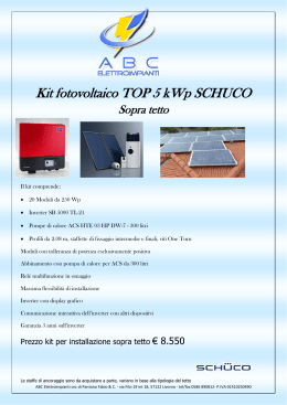
MANUALE D’ISTRUZIONI ALL’USO, INSTALLAZIONE E ALLA MANUTENZIONE USE, INSTALLATION AND MAINTENANCE INSTRUCTIONS MANUAL ITALIANO 1 1.1 1.2 2. 3. 4. 5 6 7 7.1 8 8.1 9 9.1 9.2 9.2.1 9.2.2 9.2.3 9.2.4 10 11 1.1 INDICE DATI DI IDENTIFICAZIONE GARANZIA MAGAZZINAGGIO AVVERTENZE DATI TECNICI FUNZIONALITA’ INSTALLAZIONE ELETTRICA RIFERIMENTI E MORSETTI DI COLLEGAMENTO RIFERIMENTI E COLLEGAMENTI PER IMPIANTI CON UN HERTZ TWIN PULSANTI DI COMANDO E SEGNALAZIONI LUMINOSE PANNELLO SINOTTICO COMANDI AVVIAMENTO DELL’IMPIANTO TABELLA PARAMETRI VISUALIZZATI SENZA PASSWORD MODALITA’ PER IMPOSTARE I PARAMETRI NELL’HERTZ TWIN TABELLA DEI PARAMETRI DA IMPOSTARE NELL’HERTZ ONE MASTER TABELLA DEI PARAMETRI DA IMPOSTARE NELL’HERTZ ONE SLAVE VERIFICA DEL CORRETTO FUNZIONAMENTO TABELLA DEI CODICI ALLARMI ELENCO PEZZI DI RICAMBIO DICHIARAZIONE DI CONFORMITA’ pag. 1 1 1 1 2 2 3 3 4 5 6 7 8 8 8 9 10 11 12 12 25 DATI DI IDENFICAZIONE Dati costruttore: EBARA PUMPS EUROPE S.p.A. SEDE LEGALE Via Campo Sportivo,30 38023 CLES (TN) ITALIA Telefono: 0463/660411 Fax:0463/422782 DIREZIONE DI STABILIMENTO Via Pacinotti, 32 36040 Brendola (VI) ITALIA Telefono: 0444/706811 Fax: 0444/706950 TELEX: 480536 Web site: www.ebaraeurope.com 1.2 GARANZIA L’INOSSERVANZA DELLE INDICAZIONI FORNITE IN QUESTO LIBRETTO ISTRUZIONI, E/O L’EVENTUALE INTERVENTO NELL’HERTZ ONE, NON EFFETTUATO DAI NOSTRI CENTRI ASSISTENZA, INVALIDERANNO LA GARANZIA E SOLLEVERANNO IL COSTRUTTORE DA QUALSIASI RESPONSABILITA’ IN CASO D'INCIDENTI A PERSONE O DANNI ALLE COSE E/O ALL’ HERTZ ONE STESSO. 2. MAGAZZINAGGIO Un lungo periodo d’inattività in condizioni di magazzinaggio precarie, può provocare danni alle apparecchiature, facendole diventare pericolose nei confronti del personale addetto all’installazione, ai controlli ed alla manutenzione. E’ buona regola procedere ad un corretto magazzinaggio dell’HERTZ TWIN, avendo particolare cura di osservare le seguenti indicazioni : − deve essere riposto in un luogo completamente asciutto e lontano da fonti di calore. − deve essere perfettamente chiuso ed isolato dall’ambiente esterno, al fine di evitare l’ingresso d'insetti, umidità e polveri che potrebbero danneggiare i componenti elettrici compromettendo il regolare funzionamento. 2 ITALIANO 3. AVVERTENZE Prima di procedere all’installazione leggere attentamente questa documentazione. E’ indispensabile che l’impianto elettrico ed i collegamenti siano realizzati da personale qualificato ed in possesso dei requisiti tecnici indicati dalle norme di sicurezza riguardanti l’installazione e la manutenzione degli impianti tecnici del paese d’installazione del prodotto. Il mancato rispetto delle norme di sicurezza, oltre a creare pericolo per l’incolumità delle persone e danneggiare le apparecchiature, farà decadere ogni diritto di intervento in garanzia. Per personale qualificato s’intende colui che per formazione, esperienza ed istruzione, conoscenza delle relative norme, prescrizioni provvedimenti per la prevenzione degli incidenti e sulle condizioni di servizio, è stato autorizzato dal responsabile della sicurezza dell’impianto ad eseguire qualsiasi necessaria attività ed in questa essere in grado di conoscere ed evitare qualsiasi perico1o. (Definizione per il personale tecnico IEC 364). Verificare che l’HERTZ TWIN e il gruppo non abbiano subito danni dovuti al trasporto o al magazzinaggio. In particolare occorre controllare che l’involucro esterno sia perfettamente integro ed in ottime condizioni ; tutte le parti interne dell’HERTZ TWIN (componenti, conduttori, ecc.) devono risultare completamente privi di tracce di umidità, ossido o sporco : procedere eventualmente ad una accurata pulizia e verificare l’efficienza di tutti i componenti contenuti nell’HERTZ TWIN ; se necessario, sostituire le parti che non risultassero in perfetta efficienza. E’ indispensabile verificare che tutti i conduttori dell’HERTZ TWIN risultino correttamente serrati nei relativi morsetti. In caso di lungo magazzinaggio (o comunque in caso di sostituzione di qualche componente) è opportuno eseguire nell’ HERTZ TWIN tutte le prove indicate dalle norme EN 60204-1. LEGGERE ATTENTAMENTE QUANTO RIPORTATO NELLA TARGHETTA INTERNA ALL’HERTZ TWIN. Prima di fare qualunque intervento all’interno del quadro elettrico disinserire HERTZ TWIN dalla rete elettrica e attendere 3 minuti. 4. DATI TECNICI − tensione nominale 230 V +10%, - 15%. d’alimentazione : 1 + neutro. − fasi : 50-60 Hz − frequenza : Due Due − numero pompe collegabili : − Modelli quadro: HERTZ HERTZ TWIN TWIN 2x 1,1M 2x 1,5 T 2x1,1 2x1,5 − Potenza nominale massima di impiego(kW) (motori monofasi): 2x8 − Corrente nominale massima di impiego (A) (motori monofasi): Motori monofasi − Limite di corrente x 60 sec. (A): HT 2x1,1M – HT 2x1,5T. − Limite corrente max di picco (A): HT 2x1,1M – HT 2x1,5T. − Frequenza di modulazione (KhZ): − Limiti d’impiego temperatura ambiente : − Limite temperatura ambiente di stoccaggio : − Umidità relativa (senza condensazione): − Altitudine max : − Grado di protezione : − Costruzione dei quadri: 2x8 Motore trifase (collegato a triangolo) 1,5 volte la corrente nominale impostata per 60 secondi (autoripristinante per tre volte, ripristino manuale al quarto intervento). 35 A (autoripristinante per tre volte, ripristino manuale al quarto intervento). 10 kHZ PWM vettoriale. -10°C + 50°C -25°C +55°C 50% a 40°C MAX (90% a 20°C ). 1000 m (s.l.m.); declassamento della corrente del 2% ogni 100 m sopra i 1000 m. IP55. Secondo EN 60204-1, EN 60439-1, Standard EMC applicati: EN61000-6-1, EN61000-6-3 per impiego civile. Costruzione nel rispetto della direttiva RHOS del 2002. 3 ITALIANO 5. FUNZIONALITA’. GLI HERTZ TWIN predispongono il funzionamento del gruppo come segue: − Avviamento e controllo delle elettropompe a velocità variabile. − Pulsanti da marcia e arresto per ogni elettropompa con relative segnalazioni luminose. (vedi cap. 8). − Pulsanti per la parametrizzazione dell’impianto. ((vedi cap. 8). − Visualizzazione con display a quattro digit, dei parametri istantanei di impianto: (vedi tab. 9.1). − Visualizzazione con display a quattro digit, dei parametri da impostare (vedi tabella 9.2.1 e 9.2.2). − Protezione delle elettropompe con indicazione nella lista degli allarmi, del tipo di allarme intervenuto (vedi tabella 9.2.3). − Controllo delle ore di lavoro di ogni elettropompa con indicazione della manutenzione. − Arresto automatico dell’impianto, dopo un minuto, nelle condizioni di portata a zero litri/min. − Rotazione dell’ordine di avviamento delle elettropompe . − Ripartenza automatica con una pressione di riferimento ridotta di 0,5 bar onde evitare frequenti avviamenti. − Protezione dell’HERTZ TWIN e della linea di alimentazione con fusibili per ogni inverter. − Partenza automatica dell’inverter fermo in caso di fuori servizio dell’inverter in marcia (intervento dei fusibili, intervento della protezione contro il sovraccarico. − Completo di sezionatore generale con blocco porta. 6. INSTALLAZIONE ELETTRICA. Rispettare rigorosamente i valori d’alimentazione elettrica indicati nella targhetta dati . Il quadro elettrico deve essere installato su delle superfici asciutte in atmosfera prive di gas ossidanti ne tantomeno corrosivi ed esenti da vibrazioni. Se installato all’aperto, il quadro deve essere il più possibile protetto dall’irraggiamento diretto; è necessario, provvedendo con opportuni accorgimenti, mantenere la temperatura esterna al quadro compresa nei limiti di impiego elencati nel cap. 4. Le temperature elevate portano ad un invecchiamento accelerato di tutti i componenti, determinando disfunzioni più o meno gravi. E’ inoltre opportuno garantire la chiusura stagna dei pressacavi da parte di chi effettua l’installazione. Assicurarsi che l’interruttore generale del quadro di distribuzione di energia sia in posizione OFF (O) e che nessuno né possa ripristinare accidentalmente il funzionamento, prima di procedere al collegamento dei cavi di alimentazione ai morsetti L1 - N del sezionatore. Osservare scrupolosamente tutte le disposizioni vigenti in materia di sicurezza e prevenzione infortuni. Assicurarsi che tutti i morsetti siano completamente serrati. Eseguire i collegamenti dei cavi in morsettiera in accordo allo schema elettrico riportato a pag 6. Controllare che tutti i cavi di collegamento siano in ottime condizioni e con la guaina esterna integra. ATTENZIONE! Installare nell’ impianto un interruttore differenziale da 30 mA, Classe A, protetto contro scatti intempestivi ritardo allo scatto di 0.5 secondi. Prevedere la protezione contro i cortocircuiti della linea di alimentazione, mediante fusibili tipo “AM” da: MODELLI HERTZ HERTZ TWIN HERTZ TWIN TWIN 2 x-1,1M 1x-3T CALIBRO DIMENSIONI 20 A AM 10x38 20 A AM 10x38 Si raccomanda un corretto e sicuro collegamento a terra dell’impianto come richiesto dalle normative vigenti in materia. A seconda della sezione del cavo utilizzata, limitare la lunghezza massima del cavo di alimentazione. Verifiche strumentali a carico dell’installatore: a) Continuità dei conduttori di protezione e dei circuiti equipotenziali principali e supplementari; b) Resistenza di isolamento dell’impianto elettrico; c) Prova di efficienza della protezione differenziale; d) Prova di tensione applicata; e) Prova di funzionamento. 4 ITALIANO 7 RIFERIMENTI E MORSETTI DI COLLEGAMENTO FU1 Fusibile di protezione della parte di potenza dell’inverter contro i corti circuiti da 10 A Gg mod. 10x38 . MASTER FU1 SLAVE FU2 L'intervento inibisce il funzionamento della pompa alimentata da inverter i rimanenti circuiti e elettropompe restano attivi. Togliere tensione prima di procedere alla manutenzione e attendere 3 minuti per l’ azzeramento delle tensioni interne. Fusibile di protezione dei circuiti ausiliari dell’inverter, contro corti circuiti, da 1 A rapido mod. 5x20. MASTER FU2 SLAVE ALARM 1– 2—3 MASTER ALARM 1– 2—3 SLAVE REMOTE CONT. INV MASTER 4–5 REMOTE CONT. INV SLAVE 4–5 PR.TR. 6-7 - 9 MASTER PR.TR. 6-7 - 9 SLAVE L - N U –V -W 14 – 15 – 15A L–N U–V-W 14 – 15 –15A L'intervento inibisce il funzionamento del quadro e spegne tutte le segnalazioni. Togliere tensione prima di procedere alla manutenzione e attendere 3 minuti per l’ azzeramento delle tensioni interne. Morsetti per segnalare a distanza eventuali allarmi del quadro come riportato in tab 9.2.3. Caratteristiche di contatto: (contatto N.A – N.C. da 5 A 250 V). Morsetti per segnalare a distanza eventuali allarmi del quadro come riportato in tab 9.2.3. Caratteristiche di contatto: (contatto N.A – N.C. da 5 A 250 V). Morsetti di collegamento del controllo remoto configurabile nel parametro Sin come: - comando remoto caratteristiceìhe contatto N.O. per la partenza e arresto TWIN. ( Nel caso di utilizzo togliere il ponticello di by-pass previsto di serie tra i morsetti n° 4 e 5 della morsetiera derl MASTER). - comando da un galleggiante caratteristiceìhe contatto N.O. Caratteristiche di ingresso:24 V a.c. 0.04 A . Morsetti NON UTILIZZATI. Morsetti di collegamento del trasmettitore di pressione PR.TR1. per il controllo di velocità dell’elettropompa n° P1 e della pressione di impianto da collegare all’inverter master. Attenzione rispettare la corrispondenza: Morsetto 6 alimentazione. Morsetto 7 ingresso segnale. Morsetto 8 per il collegamento a terra dello schermo del cavo del trasduttore. Caratteristiche di ingresso: 15 V d.c. 4-:-20 mA. Morsetti NON UTILIZZATI . I comandi esterni non richiedono collegamento a optoisolamento certificati. Collegamenti dell’elettropompa P1 all’inverter MASTER. Rispettare rigorosamente la corrispondenza prevista. Passare tre spire nel nucleo di ferrite in dotazione. Collegare lo schermo al collegamento di terra . Collegamenti dell’elettropompa P2 all’inverter SLAVE. Rispettare rigorosamente la corrispondenza . Passare tre spire nel nucleo di ferrite in dotazione. Collegare lo schermo al collegamento di terra . 5 in quanto sono stati usati sistemi di START FU1 10A gG 230V L1 N ! ! SHIFT DECREASE INCREASE ENTER Attention: Slave TR.P1 Before to do any intervention inside of electric board switch off the power supply and wait 3 minutes STOP 6 LINE 230V 50-60HZ Slave Before to do any intervention inside of electric board switch off the power supply and wait 3 minutes Attention: P1 STANDBY Attenzione: ENTER STOP P1 ON Prima di fare qualunque intervento all'interno del quadro elettrico disinserire hertz one dalla rete elettrica e attendere 3 minuti Master DECREASE P1 Attenzione: ! SHIFT INCREASE FLOAT / REMOTE CONTROL CN1 STANDBY CN1 Prima di fare qualunque intervento all'interno del quadro elettrico disinserire hertz one dalla rete elettrica e attendere 3 minuti Master ! P1 START ON FU1 10A gG 230V ITALIANO 7.1 RIFERIMENTI E COLLEGAMENTI ELETTRICI PER IMPIANTI CON UN HERTZ TWIN 2x1,1M - 2X1,5T . ITALIANO 8 PULSANTI DI COMANDO E INDICAZIONI LUMINOSE Rif. Funzione. simboli ! P1 Indicazione luminosa rossa che indica allarme generico con codice riportato nel display Elenco allarmi riportati in tabella 9.2.3. Indicazione luminosa gialla che segnala elettropompa P1 alimentata dall’inverter MASTER predisposta per la partenza. INV. MASTER P1 Indicazione luminosa verde che segnala elettropompa P1 alimentata . INV. MASTER STOP Tasto per escludere l’elettropompa P1 dalla marcia automatica; il led P1 si spegne. INV. MASTER START MANUAL P1 START = Premuto per 1 secondo, predispone la partenza AUTOMATICA dell’elettropompa P1. MANUAL = Premuto più di 5 secondi, attiva la partenza dell’elettropompa, al rilascio si arrresta. INV. MASTER P1 Indicazione luminosa gialla che segnala elettropompa P1 alimentata dall’inverter MASTER predisposta per la partenza. INV. SLAVE P1 Indicazione luminosa verde che segnala elettropompa P1 alimentata . INV. SLAVE STOP Tasto per escludere l’elettropompa P1 dalla marcia automatica; il led P1 si spegne. INV. SLAVE START MANUAL P1 START = Premuto per 1 secondo, predispone la partenza AUTOMATICA dell’elettropompa P1. MANUAL = Premuto più di 5 secondi, attiva la partenza dell’elettropompa, al rilascio si arrresta. INV. SLAVE Tasto per confermare il dato modificato. Tasto per incrementare il numero da modificare o passare nella riga superiore dei parametri . QS1 Tasto per diminuire il numero da modificare o passare nella riga inferiore dei parametri . Tasto per scegliere la cifra da modificare. Interruttore sezionatore della linea di alimentazione con maniglia di blocco porta lucchettabile. 7 DECREASE ! ALARM SHIFT DECREASE INCREASE ENTER ENTER STOP STANDBY M ANUAL START ON MANUAL START 8 SHIFT DECREASE INCREASE ENTER Via Campo Sportivo, 30 - 38023 Cles (TN) - Italy Via Pacinotti, 32 - 36040 Brendola (VI) - Italy Phone: +39 0444 706811 http:/ /www.ebaraeurope.com ! ALARM EBARA Pumps Europe S.p.A. HERTZ TWIN M T STOP STOP STANDBY M ANUAL START ON 8.1 SHIFT INCREASE ! ITALIANO PANNELLO SINOTTICO COMANDI ITALIANO 9 AVVIAMENTO DELL’IMPIANTO 9.1 Tabella parametri visualizzati, senza password. All’accensione l’HERTZ TWIN visualizza la P. 00.0 = Pressione istantanea di impianto. Tutti i led sono spenti e le elettropompe non devono partire. Per accedere a tutti gli altri parametri riportati in tabella digitare il tasto . Digitare il tasto per visualizzare la Pressione di istantanea di impianto. ELENCO PARAMETRI ISTANTANEI SEMPRE VISUALIZZATI Sigla Descrizione Parametro P. 00.0 r-00.0 F00.0 A00.0 nAn1 PSET CP AL 0 SrE5 PASS 9.2 Pressione istantanea impianto. Pressione di set. Frequenza di rotazione del motore alimentato da inverter. Assorbimento del motore della pompa uno. Ore di lavoro effettuate dal motore M1 (una unità visualizzata corrisponde a 10 ORE di lavoro). Taratura della pressione di impianto da mantenere costante. Taratura delle oscillazioni di pressione da ridurre al minimo (impostate < 50 risposta lenta inverter, > 50 risposta veloce dell’inverter) . Memoria allarmi: vedere quanto riportato in tabella 9.2.3. Software release del S.W. 05 del 15/02/2010 Password da inserire: 2222. Modalità per impostare i parametri nell’HERTZ TWIN. Per accedere alla programmazione procedere come segue: Digitare il tasto fino alla riga più in basso il dispaly indica: PASS. Digitare il tasto per accedere alla pagina per l’inserzione dalla PASSWORD; il display indica: _ _ _0. Digitare il tasto per entrare nella pagina; il dispaly indica: _ _ _ 0. Digitare il tasto fino al 2 e il dispalay indic a: _ _ _ 2. Digitare il tasto per entrare nuovamente nella pagina; il display indica: _ _12. Digitare il tasto fino al 2 e il display indic a: _ _ 22. Digitare il tasto per passare alla terza cifra da modificare e procedere come per le altre fino ad avere visualizzato 2222. Digitare il tasto ; e compare il primo parametro da modificare: il display indica: (A). Dalla posizione di cui sopra, si entra nella tabella 9.2..1 sotto riportata a pag. 10. (Ritorno automatico dopo 10 minuti alla tabella 9.1 e al parametro pressione istantanea di impianto). 9 ITALIANO 9.2.1 TABELLA DEI PARAMETRI DA IMPOSTARE NELL’HETZ ONE MASTER. Per la messa in servizio, modificare unicamente i parametri in grassetto relativi ai dati di targa dei motori e delle prestazione idrauliche delle pompe, utilizzando i tasti per introdurre la password. Parametro VEL ad autoimpostazione in funzione dei parametri PSET e Pn; confermare il dato con i tasti Sigla Dati di Visualiz. Descrizione fabbrica Parametro Taratura limite corrente del motore M1 alimentato da inverter. 8.0 A CI (Impostare la corrente di targa del motore). Correzione nel tempo dell'errore tra la pressione di impianto e la P.Riferimento. (Mantenere il valore di fabbrica) Pn Pressione nominale pompa a 0 litri. VEL Pr VrP rP InTr PH2O PPEr PFS 100 8 SHIFT e ENTER .. Campo di regolazione Unità di misura 0-:-10 Ampere 0-:-255 DATO 0.1-:-25.5 Bar (Impostare la pressione della pompa a portata zero). Set del livello di velocità minima dell'inverter al di sotto della quale è abilitato l’arresto delle pompe due e tre. Confermare il valore con i tasti e . Eventualmente, diminuire il dato per ridurre eventuali partenze indesiderate delle pompe due e tre. Pressione di ripartenza e fascia di pressione dentro la quale non vi è correzzione di velocità dell’HERTZ ONE. (Mantenere il valore di fabbrica) Set del livello di velocità minima dell'inverter al di sotto della quale è abilitato l’arresto dell’inverter. (Mantenere il valore di fabbrica) Riduzione pressione di riferimento per arrestare la pompa con inverter. (Mantenere il valore di fabbrica). Tempo di intervallo per introdurre la riduzione del PSET per arrestare la pompa sotto inverter. (Mantenere il valore di fabbrica) Set di pressione minima al di sotto della quale il controllo arresta la pompa per mancanza acqua all’aspirazione. (Mantenere il valore di fabbrica; aumentare in impianti con colonna d’acqua superiore a 5 mt). Set Pressione dove l’HERTZ ONE esclude tutte le pompe. P.Pericolo = PSETx1,5 x (Pn –PSET). (Mantenere il valore di fabbrica) Pressione di fondo scala del Trasmettitore di pressione in uso. Press. Sensore. (Mantenere il valore di fabbrica) 70 0-:-100% % 0,3 0,0-:-2 Bar 85 0-:-100% % 0,5 0,0-:-2 bar 10 0,0-:-99 secondi 0,5 0-:-25,5 Bar 100 0.0-:-100 % 10 0-:-25,5 DATO TIP Selezione impianto a una o due . (Mantenere il valore di fabbrica) 2 1,2,3 DATO roT Senso di rotazione motore. 1= rotazione oraria, 2= rotazione antioraria. 1 1-2 DATO Addr Indirizzo porta seriale. PC DATO - Comunicazione seriale tra HERTZ ONE: - DUE HERTZ ONE: 1° HO impostato, 1, 2° HO impostato , 2. 1 SEO. TnAm Ora dello scambio giornaliero dell'ordine di avviamento della pompa 2^ e 3^. Impostato 0 = sequenza di partenza prima la 2^ pompa poi la 3^ pompa. Impostato tra 1 a 24 = scambio dell’ordine di partenza in base l’ora impostata. Impostato 25 = scambio dell’ordine di partenza ad ogni ripartenza del gruppo. Ora Manutenzione Pompe ( una unità indicata corrisponde a 10 ore di lavoro) Interv. Man. P1 Interv. Man. P2 Interv. Man. P3 1000 (Mantenere il valore di fabbrica) 1°H0 master 25 0-:-25 25 600 0-:-9999 unità Acc. Tempo avviamento inverter da VEL. Min alla velocità MAX. 1 1-:-3 secondi F.F. Taratura del fondo scala della frequenza max uscita inverter: 50 HZ 60 HZ Selezione velocità minima sotto la quale l'inverter viene arrestato. 50 50/60 HZ 50 0-:-100% % Configurazione dell'ingresso remoto collegato ai morsetti 4-5 del MASTER come: - 0 = REMOTE CONTROL - 1 = GALLEGGIANTE MANCANZA ACQUA 1 0-:-1 - LLS S In 10 9.2.2 ITALIANO TABELLA DEI PARAMETRI DA IMPOSTARE NELL’HETZ ONE SLAVE. Per la messa in servizio, modificare unicamente i parametri in grassetto relativi ai dati di targa dei motori e delle prestazione idrauliche delle pompe, utilizzando i tasti per introdurre la password. Parametro VEL ad autoimpostazione in funzione dei parametri PSET e Pn; confermare il dato con i tasti Sigla Dati di Visualiz. Descrizione fabbrica Parametro Taratura limite corrente del motore M1 alimentato da inverter. 8.0 A CI (Impostare la corrente di targa del motore). Correzione nel tempo dell'errore tra la pressione di impianto e la P.Riferimento. (Mantenere il valore di fabbrica) Pn Pressione nominale pompa a 0 litri. VEL Pr VrP rP InTr PH2O PPEr PFS SHIFT e ENTER .. Campo di regolazione Unità di misura 0-:-10 Ampere 100 0-:-255 DATO 8 0.1-:-25.5 Bar 70 0-:-100% % 0,3 0,0-:-2 Bar 85 0-:-100% % 0,5 0,0-:-2 bar 10 0,0-:-99 secondi 0,5 0-:-25,5 Bar 100 0.0-:-100 % 10 0-:-25,5 DATO (Impostare la pressione della pompa a portata zero). Set del livello di velocità minima dell'inverter al di sotto della quale è abilitato l’arresto delle pompe due e tre. Confermare il valore con i tasti e . Eventualmente, diminuire il dato per ridurre eventuali partenze indesiderate delle pompe due e tre. Pressione di ripartenza e fascia di pressione dentro la quale non vi è correzzione di velocità dell’HERTZ ONE. (Mantenere il valore di fabbrica) Set del livello di velocità minima dell'inverter al di sotto della quale è abilitato l’arresto dell’inverter. (Mantenere il valore di fabbrica) Riduzione pressione di riferimento per arrestare la pompa con inverter. (Mantenere il valore di fabbrica). Tempo di intervallo per introdurre la riduzione del PSET per arrestare la pompa sotto inverter. (Mantenere il valore di fabbrica) Set di pressione minima al di sotto della quale il controllo arresta la pompa per mancanza acqua all’aspirazione. (Mantenere il valore di fabbrica; aumentare in impianti con colonna d’acqua superiore a 5 mt). Set Pressione dove l’HERTZ ONE esclude tutte le pompe. P.Pericolo = PSETx1,5 x (Pn –PSET). (Mantenere il valore di fabbrica) Pressione di fondo scala del Trasmettitore di pressione in uso. Press. Sensore. (Mantenere il valore di fabbrica) TIP Selezione impianto a una o due o tre pompe. (Mantenere il valore di fabbrica) 1 1,2,3 DATO roT Senso di rotazione motore. 1= rotazione oraria, 2= rotazione antioraria. 1 1-2 DATO Addr Indirizzo porta seriale. PC DATO - Comunicazione seriale tra HERTZ ONE: - DUE HERTZ ONE: 1° HO impostato, 1, 2° HO impostato , 2. 2 2°HO=slave SEO. TnAm Ora dello scambio giornaliero dell'ordine di avviamento della pompa 2^ e 3^. Impostato 0 = sequenza di partenza prima la 2^ pompa poi la 3^ pompa. Impostato tra 1 a 24 = scambio dell’ordine di partenza in base l’ora impostata. Impostato 25 = scambio dell’ordine di partenza ad ogni ripartenza del gruppo. Ora Manutenzione Pompe ( una unità indicata corrisponde a 10 ore di lavoro) Interv. Man. P1 Interv. Man. P2 Interv. Man. P3 1000 (Mantenere il valore di fabbrica) 0 0-:-25 25 600 0-:-9999 unità Acc. Tempo avviamento inverter da VEL. Min alla velocità MAX. 1 1-:-3 secondi F.F. Taratura del fondo scala della frequenza max uscita inverter: 50 HZ 60 HZ Selezione velocità minima sotto la quale l'inverter viene arrestato. 50 50/60 HZ 50 0-:-100% % Configurazione dell'ingresso remoto collegato ai morsetti 4-5 del MASTER come: - 0 = REMOTE CONTROL - 1 = GALLEGGIANTE MANCANZA ACQUA 1 0-:-1 - LLS S In 11 9.2.3 ITALIANO VERIFICA DEL CORRETTO FUNZIONAMENTO. 1) Ad impostazioni effettuate nella tabella 9.2.1, premere il tasto istantanea. fino a fare comparire il parametro P 00,0 pressione START 2) Con valvola di mandata aperta su un quarto della capacità di portata max del gruppo, premere il tasto MANUAL ,e P1 l’indicazione gialla si deve accendere automaticamente. P1 3) Se la pressione di impianto è minore di PSET, la pompa uno alimentata da inverter si mette in rotazione e il led verde si accende; la pressione deve aumentare gradualmente fino alla pressione di set eeventualmente, l’inverter deve ridurre la velocità al motore per mantenere la pressione impostata. START 4) Premere il tasto MANUAL delle pompe due e tre i rispettivi led gialli si devono accendere ma le pompe non devono partire. 5) Aprire gradualmente la valvola di mandata, la frequenza del motore uno deve andare fino a 50 HZ, e superati due secondi, si deve avviare la seconda elettropompa a ripristinare la pressione di impianto ed eventualemnte la velocità della pompa uno deve ridursi per evitare sovrapressioni. 6) Aprire nuovamente la valvola di mandata fino al max , la frequenza del motore uno deve andare fino a 50 HZ e superati i due secondi, si deve avviare la terza elettropompa a ripristinare la pressione di impianto ed eventualmente la velocità della pompa uno deve ridursi per evitare sovrapressioni. 7) Alla successiva ripartenza di tutte e tre le elettropompe, la pompa uno parte alimentata con inverter mentre le rimanenti due si scambiano l’ ordine di partenza. 8) Dalla condizione di portata max chiudere gradualmente la valvola la pressione deve mantenersi nei limiti di fabbrica +0,2 bar rispetto la PSET e quando la frequenza della pompa uno scende al di sotto del parametro VEL, la pompa in cascata si deve arrestare. 9) Nel momento dell’arresto, la pompa uno alimentata da inverter deve compensare se necessario, con aumenti di velocità, la pressione di impianto. Se l’inverter è lento a compensare le sovra o sotto pressioni, aumentare il parametro CP . Se nell’impianto ci sono oscillazzioni di pressione al variare della portata, ridurre il parametro CP. 10) Nella condizione della sola pompa uno in marcia, chiudere gradualmente e totalmente la volvola e attendere il tempo (60 sec max) per l’arresto automatico della pompa ; tutti i led verdi si devono spegnere, i led gialli restano accesi a segnalare elettropompe predisposte per la marcia. 11) Eventuali condizioni di allarmi segnalati del led rosso ! devono essere analizzati nella tabella 9.2.3. 12) Verificare la partenza in cascata del secondo HERTZ ONE verificando che il primo abbia raggiunto la velocità max di 50 HZ e che siano passati due secondi. Se la richiesta d’acqua non aumenta si deve notare una riduzione di frequenza dei due HERTZ ONE . Se la richiesta d’acqua aumenta entrambi gli HERTZ ONE aumenteranno la frequanza fino a 50 HZ. Chiudere le valvole di mandata e entrambi gli HERTZ ONE devono ridurre la frequenza fino ad un valore inferiore del dato impostato in VEL, dopo due secondi uno dei due HERTZ ONE si deve escludere. L’HERTZ ONE rimasto in marcia, temporaneamente aumenterà la sua velocità se la valvola permane parzialmente aperta altrimenti ridurrà la sua velocità per poi arrestarsi. Verificare alla prossima apertura della valvola di mandata, lo scambio dell’ordine di partenza degli HERTZ ONE. 12 ITALIANO TABELLA DEI CODICI ALLARMI VISUALIZZATI DALL’HETZ TWIN. 9.2.4 ELENCO ALLARMI AL1 CAUSA ALLARME AL2 - AL4 AL8 Ore lavoro motori, superate Nell’impostazione TnAm - AL16 - AL32 - PSET>Pn Pn>PF.S. sensore Collegamento trasduttore interrotto o invertito. Sovraccarico motori (tre autoripristini ogni minuto manuale al quarto). Guasto fusibili linea e controllo. Ripristino manuale. Protezione inverter: - limite di corrente inverter > di 35A. - Sottotensione Per < del+20% di Vn. - Sovratensione Per > del +20% di Vn. - Sovratemperatura Per > di 90°C Sovrapressione EFFETTO SULLA SEGNALAZIONE LL1 Accesa a luce fissa EFFETTO SULL’ IMPIANTO P1 , P2 Funzionano regolarmente RELE’ DI ALLARME REM. Segnala a distanza Accesa a luce fissa INDICAZIONE SUL DISPLAY AL1- 1M1 - 2 M2 - 3 M3 AL2 P1, P2 restano ferme Segnala a distanza Accesa a luce fissa AL4 P1, P2 restano ferme Segnala a distanza Accesa a luce fissa AL8 (lampeggiante prime tre volte fisso al quarto) e indica: - a 8 = P1 fault, - b 8 = P2 fault AL16 (lampeggiante prime tre volte fisso al quarto) Pompa in sovraccarico Segnala a distanza La pompa resta ferma e parte l’altro HERZT ONE Segnala a distanza AL 32 Arresta l’impianto Ripartenza automatica dopo 5 sec e al rientro della pressione Arresta l’impianto Ripartenza automatica alla chiusura del galleggiante. Arresta l’impianto dopo un min. di pressione 0, tempo ripristino 15 minuti. Segnala a distanza Accesa a luce fissa Accesa a luce fissa AL64 Accesa a luce fissa Mancanza acqua. - controllo da Ripristino automatico alla galleggiante chiusura del galleggiante. esterno. - controllo Mancanza acqua. automatico Ripristino automatico per tre Accesa a luce fissa SET sotto volte manuale al quarto. pressione min. H2O ATTENZIONE: più allarmi presenti, vengono visualizzati come somma degli stessi: - allarme 12 = ad allarmi 4+8. - allarme 24 = ad allarmi 8+16. - Allarme 68 = ad allarmi 4+64 - Allarme 72 = ad allarmi 8+64. AL64 (lampeggiante finchè esiste l'allarme) AL64 La segnalazione MANUTENZIONE MOTORI AL 1, è esclusa portandosi con il cursore Segnala a distanza Segnala a distanza e selezionando alla fine della tabella 9.1 il parametro TnAm relativo al motore che ha raggiunto le ore di funzionamento impostate, digitare con il tasto per escludere la manutenzione motore. compare la scritta ON, digitare il tasto Il display visualizza nuovamente 0000.La memoria allarmi mantiene memorizzati gli ultimi tre allarmi, per visualizzarli premere il pulsante per cancellarli premere per più di 5 secondi il pulsante 10 . ELENCO PEZZI DI RICAMBIO HERTZ TWIN 2x1,5 M RIF Codice 362302026 362302027 362302025 Descrizione SCHEDA DI POTENZA INVERTER TRIFASE Cod. 80.019.00.3 SCHEDA FILTRO MONOFASE 12° Cod. 80.029.00.0 SCHEDA DISPLAY 4 DIGITIX 1-2 MOTORI TRIFASE Cod. 80.020.00.2 13 Modello/fornitore EBARA EBARA EBARA , ENGLISH 1 1.1 1.2 2. 3. 4. 5 6 7 7.1 8 8.1 9 9.1 9.2 9.2.1 9.2.2 9.2.3 9.2.4 10 11 1.1 INDEX IDENTIFICATION DATA WARRANTY STORAGE WARNINGS TECHNICAL DATA OPERATION ELECTRICAL INSTALLATION REFERENCES AND CONNECTION TERMINALS REFERENCES AND CONNECTIONS FOR SYSTEMS WITH A HERTZ TWIN CONTROL BUTTONS AND SIGNAL LIGHTS SYNOPTIC CONTROL PANEL SYSTEM START-UP TABLE OF PARAMETERS DISPLAYED WITHOUT PASSWORD HERTZ ONE PARAMETER SETTINGS HERTZ TWIN PARAMETER SETTINGS TABLE MASTER INV HERTZ TWIN PARAMETER SETTINGS TABLE SLAVE INV OPERATIONAL CONTROL ALARM CODES TABLE SPARE PARTS DECLARATION OF CONFORMITY page 13 13 13 13 14 14 15 15 16 17 18 19 20 20 20 21 22 23 24 24 25 IDENTIFICATION DATA Manufacturer: EBARA PUMPS EUROPE S.p.A. LEGAL ADDRESS Via Campo Sportivo,30 38023 CLES (TN) ITALY Telephone: 0463/660411 Fax: 0463/422782 FACTORY ADDRESS Via Pacinotti, 32 36040 Brendola (VI) ITALY Telephone: 0444/706811 Fax: 0444/706950 TELEX: 480536 Web Site: www.ebaraeurope.com 1.2 WARRANTY FAILURE TO COMPLY WITH THE INSTRUCTIONS PROVIDED IN THIS INSTRUCTIONS HANDBOOK AND/OR ANY SERVICING OF THE HERTZ ONE WHICH IS NOT PERFORMED BY OUR SERVICE CENTRES WILL RESULT IN INVALIDATION OF THE WARRANTY AND WILL RELIEVE THE MANUFACTURER FROM ANY LIABILITY IN THE EVENT OF PERSONAL INJURIES OR DAMAGE TO PROPERTY OR THE HERTZ ONE ITSELF. 2. STORAGE A long inactive storage period in unstable conditions may cause damage to the equipment making them hazardous to those performing the installation, controls and maintenance. It is good practice to provide proper storage for the HERTZ TWIN in compliance with the following instructions: it must be stored in a perfectly dry location, away from any heat sources. it must be perfectly sealed and isolated from the external environment, in order to prevent infiltration of moisture and dust which could damage the electrical components thereby compromising its correct operation. 14 ENGLISH 3. WARNINGS Read these instructions carefully before proceeding with the installation. The electrical system and connections must be made by qualified personnel according to the safety regulations pertaining to the installation and maintenance of technical systems in force in the country where the product is installed. In addition to generating dangers for personal safety and damage to the equipment, failure to comply with the safety regulations will result in the invalidation of all service coverage under the warranty. By qualified personnel we mean those people who, possessing the required training, experience and skills, as well as knowledge of the pertinent regulations, provisions and prescriptions regarding accident prevention and operating conditions, have been authorized by the plant safety supervisor to carry out any activity aimed at preventing safety hazards. (IEC 364 definition for technical personnel). Make sure that the HERTZ TWIN and the unit have not suffered any damage during transportation or storage. In particular, make sure that the external casing is undamaged and in perfect conditions. All the internal parts of the HERTZ TWIN (components, wires, etc) must be completely free of humidity, oxides or dirt: if this is not so, carefully clean all components within the HERTZ TWIN and ensure they are working correctly and if they are not, replace them. It is of the utmost importance that all HERTZ TWIN wires are correctly tightened in their terminals. In the event of long storage (or replacement of any of the components) all the tests specified by EN standard 60204-1 should be conducted on the HERTZ TWIN. READ THE PLATE INSIDE THE HERTZ TWIN CAREFULLY. Disconnect the HERTZ TWIN from the mains power supply and wait 3 minutes before performing any work inside the electrical panel. 4. TECHNICAL DATA rated supply voltage: phases : frequency : number of connectable pumps: Panel models: Maximum rated output (kW) (singlephase motors): 230 V +10%, - 15%. 1 + neutral 50-60 Hz Two Two HERTZ TWIN HERTZ TWIN 2x 1.1M 2x 1.5 T 2x1.1 2x1.5 Maximum rated current (A) (single2x8 2x8 single-phase motors three-phase motors phase motors): 1.6 times the set rated current for 60 seconds (three times auto-reset, manual reset − Current limit x 60 sec. (A): on the fourth) 35 A (three times auto-reset, manual reset on the fourth). − Max. peak current limit (A): 10 kHZ Rotating voltage vector. − Frequency modulation (HZ): − Operating limits at room temperature: -10°C + 50°C − Storage temperature limit: -25°C +55°C − Relative humidity 0% a 40°C MAX (90% a 20°C). (without condensation): 1000 m (a.s.l.); 2% current derating every 100 m over 1000 m. − Max. altitude: IP55. − Protection class: According to EN 60204-1, EN 60439-1, − Panels construction: Applied EMC standards: EN61000-6-1, EN61000-6-3 for civil applications. Construction in accordance with the RHOS - 2002 directive. 15 ENGLISH 5. OPERATION The HERTZ TWIN operates the unit as follows: Starting and control of all electric pump at variable speed with the inverter. Start and stop button for each electric pump with related signal light. (see chap. 8). Button for the parameterization of the system. (see chap. 8). Four digit display of the instantaneous system parameters: (see tab. 9.1). Four digit display of the settable system parameters (see tab. 9.2.1 and 9.2.2). Protection of the electric pumps with indications in the alarms list of the type of alarm tripped (see tab. 9.2.3) Control of the operating time of each electric pump with maintenance signalling. Automatic shutdown of the system after 10 seconds, when the delivery is at zero litres/min. Rotation of starting order of the electric pumps Automatic restart with a reduced reference pressure of 0.5 bar to avoid frequent starts. Fuse protection of the HERTZ TWIN and the power supply line. Including cutout switch with door locking. 6. ELECTRICAL INSTALLATION. The electrical power supply values indicated on the rating plate must be respected. The electrical panel must be installed on a dry and vibration free surface and in an environment free of oxidising and corrosive gases. If installed outside the panel must be protected as much as possible from direct irradiation. Suitable steps must be taken to ensure that the external temperature of the panel is within the limits indicated in chap. 4. High temperatures cause accelerated aging of all components causing more or less serious failures. Those performing the installation should also make sure that the cable clips are correctly sealed. Before connecting the power supply cables to the L1 – N terminals of the cutout switch, ensure that the power distribution panel cutout switch is in the OFF (O) position and that the panel operation cannot be accidentally restored again. Closely observe all the regulations in force regarding safety and accident prevention. Make sure that all the terminals are fastened securely. Connect the cables in the terminal board according to the wiring diagrams shown on page 6. Make sure that all the connection cables are in perfect condition, with the outer sheath undamaged. WARNING! Fit a Class A 30 mA differential switch on the system that is protected against inopportune tripping with a trip delay of 0.5 seconds. Make sure the power supply is protected against short circuits by means of “AM” type fuses of: HERTZ TWIN MODELS GAUGE DIMENSIONS HERTZ TWIN 2 x-1.1M 25 A AM 10x38 HERTZ TWIN 2x-1.5T 20 A AM 10X38 The system should ideally be correctly and safely grounded as required by the related standards. Limit the length of the power supply cable based on the section of the cable used. Instrumental controls to be performed by the installer: Stability of the protection conductors and of the main and auxiliary unipotential circuits Insulation resistance of the electrical system Differential protection efficiency test Applied voltage test Operating test 16 ENGLISH 7 CONNECTION REFERENCES AND TERMINALS FU1 MASTER FU1 SLAVE FU2 MASTER FU2 SLAVE ALARM 1– 2—3 MASTER ALARM 1– 2—3 SLAVE REMOTE CONT. MASTER 4–5 REMOTE CONT. SLAVE 4–5 PR.TR. 6 – 7- 9 SLAVE U – V –W 14 – 15 – 15A U–V–W 14 – 15 – 15A 10 A Gg mod. 10x38 type inverter short circuit protection fuses. 10 A Gg mod. 10x38 type inverter short circuit protection fuses. When triggered the function of the inverter supplied pump is prevented and the remaining circuits and electric pumps remain activated. Turn off the power supply and wait 3 minutes for the internal voltage to zero before performing any maintenance operations. 1 A quick-break mod. 5x20 type fuse against inverter short circuits. 1 A quick-break mod. 5x20 type fuse against inverter short circuits. When triggered the function of the panel is prevented and all signals are switched off. Turn off the power supply and wait 3 minutes for the internal voltage to zero before performing any maintenance operations. Terminals for the remote signalling of panel alarms as indicated in tab. 9.2.3. Contact characteristics: (5 A 250 V N.O – N.C. contacts). Terminals for the remote signalling of panel alarms as indicated in tab. 9.2.3. Contact characteristics: (5 A 250 V N.O – N.C. contacts). Terminals of the remote control configurable with the parameter Sin as: - contact N.O. remote control for the start and stop TWIN. (In case of using remove the bypass bridge planned series between n°4 and 5 terminals of the MASTER terminal ). - contact N.O. command by a float. Input characteristics: 24 V a.c. 0.04 A. UNUSED terminals UNUSED terminals The external commands do no require connections because certified optical isolation systems have been used. Connection of the P1 electric pump to the inverter ONE MASTER. Observe the required correspondence closely. Pass three coils in the supplied ferrite core. Connect the screen to the ground connection. Connection of the P1 electric pump to the inverter TWO SLAVE. Observe the required correspondence closely. Pass three coils in the supplied ferrite core. Connect the screen to the ground connection. 17 START FU1 10A gG 230V L1 N ! ! SHIFT DECREASE INCREASE ENTER Attention: Slave TR.P1 Before to do any intervention inside of electric board switch off the power supply and wait 3 minutes STOP 18 LINE 230V 50-60HZ Slave Before to do any intervention inside of electric board switch off the power supply and wait 3 minutes Attention: P1 STANDBY Attenzione: ENTER STOP P1 ON Prima di fare qualunque intervento all'interno del quadro elettrico disinserire hertz one dalla rete elettrica e attendere 3 minuti Master DECREASE P1 Attenzione: ! SHIFT INCREASE FLOAT / REMOTE CONTROL CN1 STANDBY CN1 Prima di fare qualunque intervento all'interno del quadro elettrico disinserire hertz one dalla rete elettrica e attendere 3 minuti Master ! P1 START ON FU1 10A gG 230V ENGLISH 7.1 ELECTRICAL REFERENCES AND CONNECTIONS FOR SYSTEMS WITH 1 HERTZ TWIN FOR THREE-PHASE MOTORS. ENGLISH 8 CONTROL BUTTONS AND SIGNAL LIGHTS Symbo Function l Ref. ! Red signal light that indicates a general alarm with displayed code Alarms list in table 9.2.3. P1 Yellow signal light that indicates that electric pump P1 is in standby. MASTER INV. P1 Green signal light that indicated that electric pump P1 is on. MASTER INV. STOP Button that stops the automatic running of electric pump P1; the P1 LED switches off. MASTER INV. START MANUAL P1 START = Pressed for 1 second, prepares the electric pump P1 for AUTOMATIC starting. MANUAL = Pressed for 5 seconds, starts the electric pump that stops when released. MASTER INV. P2 Yellow signal light that indicates that electric pump P2 is in standby. SLAVE INV. Green signal light that indicated that electric pump P2 is on. SLAVE INV. STOP Button that stops the automatic running of electric pump P2; the P1 LED switches off. SLAVE INV. START MANUAL P2 START = Pressed for 1 second, prepares the electric pump P2 for AUTOMATIC starting. MANUAL = Pressed for 5 seconds, starts the electric pump that stops when released. SLAVE INV. Button to confirm the modified data. Button to increase the number to be modified or to pass to the line above of the parameters. Button to decrease the number to be modified or to pass to the line below of the parameters Button to select the number to be modified. QS1 Mains power supply cutout switch with lockable door handle. 19 DECREASE ! ALARM SHIFT DECREASE INCREASE ENTER ENTER STOP STANDBY M ANUAL START ON MANUAL START SHIFT DECREASE INCREASE ENTER Via Campo Sportivo, 30 - 38023 Cles (TN) - Italy Via Pacinotti, 32 - 36040 Brendola (VI) - Italy Phone: +39 0444 706811 http:/ /www.ebaraeurope.com ! ALARM EBARA Pumps Europe S.p.A. HERTZ TWIN M T STOP STOP STANDBY M ANUAL START ON 8.1 SHIFT INCREASE ! ENGLISH SYNOPTIC CONTROL PANEL 20 ENGLISH 9 SYSTEM START-UP 9.1 Table of parameters displayed without password When the HERTZ TWIN is started it displays P. 00.0 = System instantaneous pressure. All LEDs are off and the electric pumps must not start. Press the button to access all other parameters indicated in the table. Press button to display the System instantaneous pressure. CONSTANTLY DISPLAYED INSTANTANEOUS PARAMETERS Parameter Description Abb. P. 00.0 r-00.0 F00.0 A00.0 nAn1 PSET CP AL 0 SrE5 PASS 9.2 System instantaneous pressure. Set pressure. Inverter powered motor rotation frequency. Pump one motor absorption. Operating hours performed by motor M1 (each displayed unit corresponds to 10 working hours). System pressure setting to be maintained constant. Setting to reduce to a minimum the pressure surging; set: (values < 50 slow inverter reaction, values > 50 fast inverter reaction) . Alarms memory: see that indicated in table 9.2.3. S.W. 05 software release dated 15/02/2010 Password to introduce: 2222. Alarm codes in table 9.2.3. HERTZ TWIN parameter settings. Proceed as follows for programming: Press button until the last line, the display shows: PASS. Press button to enter the PASSWORD page; the display shows: _ _ _0. Press button to enter the page; the display shows: _ _ _ 0. Press button Press button Press button until 2 and the display shows: _ _ _ 2. to enter the page once again; the display shows: _ _12. until 2 and the display shows: _ _ 22. Press button is displayed. to go to the next number to be modified and proceed as was done for the others until 2222 Press button ; the first parameter to modify appears: the display shows: (A). Entry is gained to table 9.2.1, illustrated below on page 10, from this position. (It automatically returns to table 9.1 and to the system instantaneous pressure parameter after 10 minutes). 21 ENGLISH 9.2.1 HERTZ TWIN PARAMETER SETTINGS TABLE IN THE MASTER INV. For start-up, modify the bold parameters related to the motor rating plate and the hydraulic performance of the pump only, using the buttons to introduce the password. The parameter VEL is auto-setting based on the PSET and Pn parameters; confirm the data with buttons SHIFT and ENTER .. Displayed Parameter abb. Factory settings Adjustment range Unit of measurement Current limit setting of the inverter powered motor M1. 8.0 0-:-10 Ampere CI (Set the rated current of the motor). Correction over time of the error between the system pressure and the reference pressure. (Maintain the factory setting) 100 0-:-255 DATA Pn Rated pressure of pump at 0 litres. A VEL Pr VrP rP InTr PH2O PPEr PFS TIP roT Addr SEO. TnAm Description 8 0.1-:-25.5 Bar (Set the pump pressure at zero delivery). Inverter’s minimum speed setting below which is enabled the cutout of pumps two and three. 0-:-100% % 0,3 0,0-:-2 Bar 85 0-:-100% % 0,5 0,0-:-2 bar 10 0,0-:-99 seconds 0,5 0-:-25,5 Bar 100 0.0-:-100 % 10 0-:-25,5 DATA Selects one or two or three pump system. (Maintain the factory setting) Dyrection rotation motor. 1=clockwise rotation 2 = anticlockwise rotation 2 1,2,3 DATA 1 1-2 DATO Serial port address. 1 1-2 DATA 25 0-:-25 25 600 0-:-9999 unit Confirm the value with buttons and . If necessary lower the value to reduce possible undesired starts of pumps two and three. Restart pressure. (Maintain the factory setting) Inverter’s minimum speed setting below which is enabled the cutout of the inverter. (Maintain the factory setting). Reference pressure reduction to stop the pump with inverter. (Maintain the factory setting). Interval time to introduce the PSET reduction to stop the inverter supplied pump. (Maintain the factory setting). Minimum pressure setting below which the control stops the pump due to the lack of intake water. (Maintain the factory setting; increase in systems with column of water greater than 5 m). Pressure setting where the HERTZ TWIN excludes all pumps. Dangerous pressure = PSETx1.5 x (Pn –PSET). (Maintain the factory setting) End scale pressure of the pressure transmitter in use. Sensor pressure (Maintain the factory setting) Serial inverters comunication. Master inv. set one, slave inv. set two Daily change over time of pumps 2 and 3 starting order. Setting 25 = starting order change over on every restart of the unit for master inv. Pump maintenance time (each displayed unit corresponds to 10 working hours) Main. Oper. P1 Main. Oper. P2 Main. Oper. P3 1000 (Maintain the factory setting) 70 Acc. Inverter start time, from minimun speed to maximum speed. 1 0,5-:-3 F.F. Maximum output inverter's frequency. 50 HZ 60 HZ Select the minimum speed below which the inverter is stopped 50 50/60 HZ 50 0-:-100% % Configuration of the remot control connected to the terminal 4 and 5 of the MASTER as: - 0 = remote control - 1 = lack of water floating 1 0-:-1 - L.L.S. S In 22 seconds ENGLISH 9.2.2 HERTZ TWIN PARAMETER SETTINGS TABLE IN THE SLAVE INV. For start-up, modify the bold parameters related to the motor rating plate and the hydraulic performance of the pump only, using the buttons to introduce the password. The parameter VEL is auto-setting based on the PSET and Pn parameters; confirm the data with buttons SHIFT and ENTER .. Displayed Parameter abb. Factory settings Adjustment range Unit of measurement Current limit setting of the inverter powered motor M2. 8.0 0-:-10 Ampere CI (Set the rated current of the motor). Correction over time of the error between the system pressure and the reference pressure. (Maintain the factory setting) 100 0-:-255 DATA Pn Rated pressure of pump at 0 litres. A VEL Description 8 0.1-:-25.5 Bar (Set the pump pressure at zero delivery). 0-:-100% % 0,3 0,0-:-2 Bar 85 0-:-100% % 0,5 0,0-:-2 bar 10 0,0-:-99 seconds 0,5 0-:-25,5 Bar 100 0.0-:-100 % 10 0-:-25,5 DATA Selects one or two or three pump system. (Maintain the factory setting) Dyrection rotation motor. 1=left rotation 2 = right rotation 2 1,2,3 DATA 1 1-2 DATO Addr Serial port address. 2 1-2 DATA SEO. Daily change over time of pumps 2 and 3 starting order. Setting 25 = starting order change over on every restart of the unit for master inv. 00 0-:-25 25 Pump maintenance time (each displayed unit corresponds to 10 working hours) Main. Oper. P1 Main. Oper. P2 Main. Oper. P3 1000 (Maintain the factory setting) 600 0-:-9999 unit Pr VrP rP InTr PH2O PPEr PFS TIP roT TnAm Inverter’s minimum speed setting below which is enabled the cutout of pumps two and three. Confirm the value with buttons and . If necessary lower the value to reduce possible undesired starts of pumps two and three. Restart pressure. (Maintain the factory setting) Inverter’s minimum speed setting below which is enabled the cutout of the inverter. (Maintain the factory setting). Reference pressure reduction to stop the pump with inverter. (Maintain the factory setting). Interval time to introduce the PSET reduction to stop the inverter supplied pump. (Maintain the factory setting). Minimum pressure setting below which the control stops the pump due to the lack of intake water. (Maintain the factory setting; increase in systems with column of water greater than 5 m). Pressure setting where the HERTZ TWIN excludes all pumps. Dangerous pressure = PSETx1.5 x (Pn –PSET). (Maintain the factory setting) End scale pressure of the pressure transmitter in use. Sensor pressure (Maintain the factory setting) 70 Serial inverters comunication. Master inv. set one, slave inv. set two Acc. Inverter start time, from minimun speed to maximum speed. 1 0,5-:-3 F.F. Maximum output inverter's frequency. 50 HZ 60 HZ Select the minimum speed below which the inverter is stopped 50 50/60 HZ 50 0-:-100% % Configuration of the remot control connected to the terminal 4 and 5 of the MASTER as: - 0 = remote control - 1 = lack of water floating 1 0-:-1 - L.L.S. S In 23 seconds ENGLISH 9.2.3 OPERATIONAL CONTROL. 1) Once the settings have been made in table 9.2.1, press button appears. until the instantaneous pressure parameter P 00,0 START P1 2) With the delivery valve open at a quarter of the unit’s maximum delivery, press button , the yellow signal should automatically light. 3) If the system pressure is lower than the PSET, the pump that is not supplied by the inverter starts to rotate and the green MANUAL P1 LED lights. The pressure should gradually increase to the set pressure otherwise, the inverter should reduce the motor speed in order to maintain the set pressure. START 4) Press button MANUAL of pumps two and three, the related yellow LEDs should light but the pumps shouldn’t start. 5) Gradually open the delivery valve, the frequency of motor one should reach 50 Hz, and after two seconds the second electric pump should start to restore the pressure of the system and the speed of the first pump should lower so as not to cause overpressure. 6) Fully open the delivery valve, the frequency of motor one should reach 50 Hz, and after two seconds the third electric pump should start to restore the pressure of the system and the speed of the first pump should lower so as not to cause overpressure. 7) The next time all three electric pumps start, pump one starts supplied by the inverter while the other two interchange the starting order. 8) With the maximum delivery, gradually close the valve, the pressure should remain within the factory limits +0.2 bar in relation to the PSET parameter and when the frequency of pump one drops below the VEL parameter, the pumps in cascade should stop one after the other. 9) When they stop the first inverter supplied pump should compensate the pressure of the system if necessary by increasing its speed. Increase the CP parameter if the inverter is slow in compensating the drop or increase in pressure. Reduce the CP parameter if pressure surges occur in the system when the delivery changes. 10) When pump one is running only, gradually and totally close the valve and wait for the pumps to automatically stop (max. 60 sec.). All green LEDs should switch off, and the yellow LEDs should remain on, signalling that the pumps are ready to start. 11) Possible alarms that are signalled by the red LED ! must be checked in table 9.2.3. 12) In systems with two and/or three and/or four HERTZ TWIN check the cascade starting of the second HERTZ ONE making sure that the first has reached the speed of 50 Hz and that two seconds have lapsed. A reduction in the frequency of the two HERTZ TWIN should be noted if the request of water does not increase. If the request of water increases, both HERTZ TWIN will increase their frequency up to 50 Hz. Close the delivery valve and both HERTZ TWIN should reduce their frequency to a value lower than the set VEL value and one of the two HERTZ TWIN should cut out after two seconds. If the valve remains partially open the HERTZ TWIN that is still running will temporarily increase its speed, otherwise it will reduce its speed and finally stop. The next time that the delivery valve is opened, check the starting order of the HERTZ TWIN. 24 ENGLISH 9.2.4 ALARM CODES TABLE DISPLAYED BY HERTZ TWIN. ALARMS CAUSE OF ALARM EFFECT ON THE DISPLAY LIST LL1 SIGNAL SIGNAL EFFECT ON THE SYSTEM REMOTE ALARM RELAY AL1 Exceeded the set TnAm working hours of the motor Permanently on AL1- 1M1 - 2 M2 P1 , P2 Operating normally Remote signal AL2 - PSET>Pn Pn>PF.S. sensor Transducer connection broken or inverted. Motors overload (three auto-resets every minute and manual on the fourth). fault line and control fuses . Manual reset Permanently on AL2 P1, P2 is stopped Remote signal Permanently on AL4 P1, P2 is stopped Remote signal Permanently on AL8 (flashing first three times, permanent on fourth) a8= P1 fault, b 8 = P2 fault Pump overload Remote signal Permanently on AL16 (flashing first three times, permanent on fourth) The pump is stopped and start with the other Hertz One. Remote signal Permanently on AL 32 System switch off. Automatic restart after 5 sec. and with return of pressure System switch off Auto-reset at the closure of the float It stopped the plant after 1 min. of pressure 0. Time of recovery: 15min. Remote signal AL4 AL8 AL16 - AL32 - Inverter protection: current limit inverter > 35A. Undervoltage For < of the +20% of Vn. Overvoltage For > of the 20% of Vn. Overtemperature For > 90°C Overpressure AL64 - Lack of water. Permanently on AL64 control : Auto-reset at the closure of the (flashing first three - external Float times, permanent on floating fourth) - automatic control set - Lack of water. Permanently on AL64 under three auto-resets every 15 minute pressure and manual on the fourth). min. H2O WARNING: several alarms together are displayed as the sum of the said alarms: - alarm 12 = alarms 4+8, - alarm 24 = alarms 8+16, - alarm 68 = alarms 4+64, - alarm 72 = alarms 8+64. Remote signal Remote signal to select the TnAm parameter at the end of table 9.1, related The AL 1 MOTOR MAINTENANCE signal is excluded by using the cursor to the motor that has reached the set number of working hours. Press the button ON appears, press the 0000 is once again displayed. button to exclude the motor maintenance. The alarm memory memorises the last three alarms, press the cancel them. 10 button to view them and press the button for more than 5 seconds to SPARE PARTS HERTZ TWIN 2x1,5 M REF Code 362302026 362302027 362302025 Description THREE-PHASE INVERTER POWER BOARD Cod. 80.019.00.3 MONOPHASE FILTER BOARD 12 A Cod. 80.029.00.0 MONOPHASE DISPLAY BOARD DIGITIX 1-2 MOTORS Cod. 80.020.00.2 25 Model/Vendor EBARA EBARA EBARA 11 DICHIARAZIONE DI CONFORMITÀ 11 DECLARATION OF CONFORMITY La Ditta EBARA PUMPS EUROPE S.p.A. Via Campo sportivo, 30 38023 CLES (TN) ITALY Sotto la propria esclusiva responsabilità dichiara che i quadri di comando pompe mod.: The Company EBARA PUMPS EUROPE S.p.A. Via Campo sportivo, 30 38023 CLES (TN) ITALY Declares under its own responsibility that the above-mentioned products: HERTZ TWIN 2x1,1M, HERTZ TWIN 2x1,5T , HERTZ TWIN 2x1,1M, HERTZ TWIN 2x1,5T , sono conformi a: Direttiva della Compatibilità elettromagnetica 2004/108/EC. Direttiva Bassa Tensione 2006/95/EC . Direttiva “RoHS” 2002 95/EC are comply with: Directive on electromagnetic compatibility no. 2004/108/EC. Directive on low voltage no. 2006/95/EC. Directive “RoHS”2002 95/EC. Legale rappresentante Legal rapresentative Brendola (VI), 30/03/2010 Cod. n. 19.011.012.4 rev. 04 del 30/03/2010 26
Scaricare