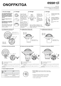
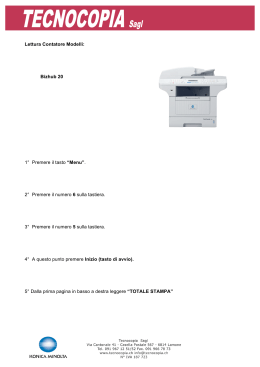
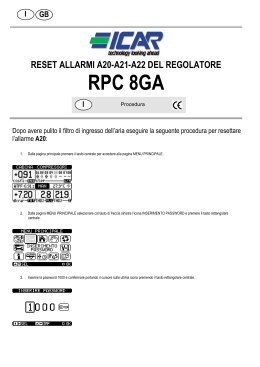
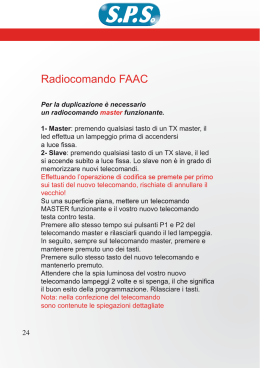
Climatizzatore Multisplit
Multisplit air conditioner
Manuale installatore
Installation manual
SMIV - SMOV Series
I prodotti elettrici ed elettronici di eventuale scarto dovranno essere disposti con i normali rifiuti domestici, ma
smaltiti a norma di legge RAEE in base alle direttive Europee 2002/96/CE e successive modifiche 2003/108/CE,
informandosi presso il Comune di residenza o presso il rivenditore nel caso in cui il prodotto venga sostituito
con uno analogo.
Possible wasted electrical or electronic devices/products should not be located together with normal
domestic waste, but disposed according to the current WEEE law in compliance with the European
Directive 2002/96/EC and following modifications 2003/108/EC. Please inform yourself at your local
ITALIANO
Note per il funzionamento
Leggere con cura questo manuale per un corretto utilizzo del condizionatore.
Quando la tensione è molto
alta, i componenti possono
venire facilmente danneggiati, quando è molto bassa,
il compressore vibra fortemente e quindi il sistema
refrigerante può danneggiarsi assieme al compressore e i componenti elettrici;
la tensione deve rimanere
costante e non subire forti
fluttuazioni.
Mai accoppiare il cavo di
Assicurarsi di togliere
alimentazione o usare proll’alimentazione quando il
unghe.
climatizzatore non viene
utilizzato per un tempo prolungato, altrimenti l’accumulo di
polvere può provocare
surriscaldamenti e incendi.
Non lasciare finestre e porte
aperte per lungo tempo
mentre il condizionatore è in
funzione altrimenti diminuisce
l’efficienza del condizionatore.
Non bloccare la presa d’aria e
le uscite delle unità interna ed
esterna.
Può diminuire l’effcienza del
condizionatore o verificarsi
malfunzionamenti.
Il gruppo di alimentazione
deve adottare un interruttore
di protezione.
Si prega di non accendere o
spegnere l'unità frequentemente, per non danneggiare
l’unità.
Spegnere l'alimentazione e
contattare il centro
assistenza se si avverte
odore di bruciato o fumo.
Tenere i liquidi infiammabili ad
oltre 1 m dall’unità .
Non tentare di riparare il
condizionatore da soli.
Possono verificarsi cortocircuiti.
Può provocare surriscaldamento o incendio.
Possono verificarsi incenti o
esplosioni.
4
Note per il funzionamento
Si prega di non tagliare o danneggiare i
cavi di alimentazione; se sono danneggiati è consigliabile di chiamare del
personale qualificato per la sostituzione.
Per regolare il flusso dell’aria regolare
le alette del condizionatore premendo
il tasto SWING sul telecomando.
Aletta
Non inserire le mani o stecchi nella
presa o nell'uscita d'aria.
Guida aletta
Non esporre piante o animali direttamente sotto il flusso d’aria.
lungo tempo per evitare problemi di salute
Non utilizzare il condizionatore per
altri scopi, come per asciugatura di
vestiti, conservazione alimenti, ecc.
Spruzzare l'acqua sul condizionatore può
causare una scossa elettrica e un malfunzionamento.
Non disporre il condizionatore vicino
a sorgenti di calore quali cucina ed
elettrodomestici.
5
Nomi e funzioni dei componenti
Unità interna
Ingresso aria
2
1
6
3
4 Uscita aria
(1) Interruttore manuale
5
(2) Pannello frontale
(3) Filtro
(4) Guida aletta
9
(5) Finestra ricezione
(6) Nastro fissazione
(7) Cavo connessione
7
(8) Tubo drenaggio
(9) Telecomando
8
Unità esterna
Air in
(1) Griglia uscita aria
(2) Valvola
1
2
Air out
Nota: le suddette figure sono solamente un esempio illustrativo, le unità acquistate
possono essere apparentemente diverse.
6
Funzionamento del telecomando
Nome e funzione dei tasti del telecomando
Nota: Assicurarsi che non ci siano ostacoli tra il ricevitore ed il telecomando. Non far cadere o
gettare il telecomando; non lasciare liquidi sul telecomando e non metterlo direttamente sotto la
luce del sole o vicino le fonti di calore.
Trasmettitore segnale
SLEEP
Tasto SLEEP
Premere questo tasto per selezionare la modalidà
Sleep On o Sleep Off. La modalità Sleep off è
quella prdefinita quando l’unità è sotto alimentazione. Dopo lo spegnimento dell’unità, la modalità
Sleep verrà annullata. Dopo l’impostazione della
modalità Sleep, l’indicatore Sleep si visualizzerà in
questa modalità, il Timer e attivo mentre questa
ultima funzione non è disponibile in modalità di
ventilazione e auto.
FAN
Tasto VENTILAZIONE
Premere questo tasto per selezionare la velocità
auto, bassa, media o alta del ventilatore. Dopo
l’elettrificazione dell’unità, la velocità auto del
ventilatore sarà quella predefinita. L’unica velocità
regolabile in modalità di ventilazione.
Telecomando
Vent. bassa
Ventilazione alta
CLOCK
Premere questo tasto per accendere l'unità, per
spegnere l’unità premere di nuovo lo stesso tasto.
La modalità Sleep verrà annullata, quando l’unità
è spenta.
Tasto MODALITA’
Premere questo tasto per selezionare l’impostare
della modalità auto, raffreddamento, deumidificazione, ventilazione o riscaldamento di calore può
essere selezionato di un modo circolare. La
modalità auto è la predefinita alimentando l’unità.
Nel funzionamento in modalità auto, la temperatura
non verrà visualizzata, nel riscaldamento sotto la
modalità auto, la temp. di partenza è 28°C (82°F),
sotto altre modalità, il valore iniziale è 25° (77°F).
AUTO
COOL
DRY
FAN
HEAT
Tasto OROLOGIO
Premere questo tasto per impostare l’orologio,
l’indicatore clock
comincia a lampeggiare. Entro
5 secondi, il valore può essere regolato premendo
il tasto + o -, se viene premuto continuamente
questo tasto per più di 2 minuti, in ogni 0.5 secondi,
il valore diceno dei minuti aumenta di unità.
Durante il lampeggiamento, se viene premuto il
tasto clock o confirm, l’indicatore verrà visualizzato
costantemente
confirmando
la
riuscita
dell’impostazione. Dopo l’elettrificazione dell’unità,
l’ora predefinita dell’orologio è 12:00 e l’indicatore
clock verrà visualizzato. Se quest’ultimo indicatore
viene visualizzato significa che l’ora visualizzata è
quella attuale del’orologio altrimenti è quella del
Timer
Tasto ON/OFF
MODE
Ventilazione media
TEMP
Tasto TEMPERATURA
Premere questo tasto per impostare la temperatura, (visualizzando the room), temp. ambiente
interna (visualizzando indoor temp), temp.
ambiente esterna (visualizzando outdoor temp), se
la temp. esterna non è visualizzata, l’unità partirà
mantenendo la condizione originale del display.
Nessun segnale visualizzato. Nota: Nel l’uso di
questo tasto, la temperatura impostata viene
visualizzata sul telecomando durante tutto il
periodo di funzionamento.
( Solo per le unità di raffreddamento e riscaldament)
7
Funzionamento del telecomando
Nome e funzione dei tasti del telecomando
Questo telecomando è universale e potrebbe essere usato per molte unità, quindi alcuni tastiche non sono
disponibili non saranno descritti qui di seguito.
+
Telecomando
-
BLOW
TURBO
Premere questo tasto per aumentare la
temp. pre-impostata. Tenete premuto
continuamente questo tasto per due
secondi, per cambiare rapidamente,
l’impostazione fino al rilascio del tasto,
dopo la trasmessione del segnale di
temperatura verrà visualizzato sul
display il simbolo di temp. (°F). La regolazione di temperatura non è disponibile
sotto la modalità auto, ma il segnale
d’impostazione può essere trasmesso
se viene premuto questo tasto.
L’intervallo d’impostazione di temp. in
centigradi è: 16°C - 30°C; che corresponde all’impostazione in Fahrenheit:
Tasto Premere questo tasto per diminuire la
temp. pre-impostata. Se viene premuto
continuamente per due secondi,
l’impostazione verà cambiata rapidamente, fino al rilascio del tasto, dopo la
trasmessione del segnale di temp. in
(°F) verrà visualizzato. La regolazione di
temperatura non è disponibile sotto la
modalità
auto,
ma
il
segnale
d’impostazione può essere trasmesso
se viene premuto questo tasto.
Tasto BLOW
Premere questo tasto per impostare la
funzione BLOW on o BLOW Off. Nella
modalità di raffreddamento e deumidificazione premere un volta questo tasto,
l'indicatore di deumidificazione verrà
visualizzato e la funzione BLOW si attiva.
Ripremendo di nuovo questo tasto per la
seconda volta, l'indicatore deumidificazione sparisce, dopo di che, la funzione
BLOW si disattiva. Dopo aver alimentato
l'unità, la funzione BLOW OFF è quella
predefinita. Premendo il tasto ON/OFF
cambiando la modalità in raffreddamento, deumidificazione, lo stato BLOW
rimarrà nella l'impostazione originale. Se
l'unità è spenta, solo la funzione BLOW
OFF che può essere regolabile ed il
segnale si trasmette. Questa funzione
non è disponibile nella modalità auto,
ventilazione e di riscaldamento.
Tasto +
LIGHT
Tasto LIGHT
Premere questo tasto se l’unità è accesa
o spenta, per impostare la funzione Light
On o Light Off. Dopo l’elettrificazione
dell’unità, la funzione predefionita è Light
On.
Tasto TURBO
Premere questo tasto in modalità di
raffreddamento o di riscaldamento per
accendere o spegnere l’unità. Dopo
l’attivazione della funzione Turbo,
l’indicatore Turbo verrà visualizzato e
sarà annullato automaticamente cambiando la modalità o la velocità del ventilatore.
8
Funzionamento del telecomando
Pulsanti e funzioni del telecomando
Quasto telecomando è universale e si può utilizzare per diverse unità.
Alcuni pulsanti possono essere relativi a funzioni non disponibili sulle unità.
TIMER ON
PULSANTE TIMER ON
-
Impostazioni Timer On: il simbolo “ON”
lampeggia, il simbolo
scompare, la
sezione numerica indica l’impostazione
del timer on. Durante i 5 sec.di lampeggio,
premendo i pulsanti ˇ oˉ si regola il
tempo nella sezione numerica, ad ogni
pressione del pulsante il valore aumenta
o diminuisce di 1 minuto. Tenendo premuto i pulsantiˇ o ˉ , dopo 2 secondi,
cambia rapidamentenel modo seguente:
nei primi 2.5 secondi, cambia di un minuto
alla volta e poi di dieci in dieci, fermo
restando il minuto impostato, nei primi
2.5 secondi.
Durante il lampeggio di 5s, premendo il
pulsante Timer l’impostazione del timer
è completata. Se è impostato il Timer On,
ripremendo il pulsante Timer, il Timer
On si cancella. Prima di impostare il
Timer, regolare l’orologio con l’orario
corrente.
Telecomando
PULSANTE SWING
-
Premere per impostare l’angolo di oscillazione
TIMER OFF
PULSANTE TIMER OFF
che varia circolarmente come sotto:
- Premendo una volta il pulsante si entra
nelle impostazioni TIMER OFF e l’icona
TIMER OFF inizia a lampeggiare
Le impostrazioni sono le stesse
OFF
del TIMER ON.
Questo telecomando è universale. Nelle
PULSANTE HEALTH
tre seguenti posizioni l’angolo di
oscillazione rimane invariato.
- Premendo queso pulsante si attivano
Health On e Off. Health On è di default
all’accensione (solo se c’è l’opzione)
Se l’aletta viene fermata quando oscilla
si blocca nella posizione attuale.
I FEEL
PULSANTE I FEEL
- Premere una volta per attivare la funzio-
indica che l’aletta si muove avanti e indietro
nelle cinque posizioni come indicato in
figura.
PULSANTE ARIA
- Premendo questo pulsante si seleziona
Air On e Air Off (solo per unità con ricircolo).
ne I FEEL e l’icona “I FEEL" viene
visualizzata. Dopo 200ms da qualsiasi
altra impostazione viene inviato il comando
I FEEL. Una volta attivata la funzione,
il telecomando invia la temperatura
rilevata all’unità interna ogni 10 minuti.
Ripremendo questo pulsante la funzione
si disattiva.
9
Funzionamento del telecomando
Guida per il funzionamento - Funzionamento generale
1. Dopo alimentazione dell’unità, premere il tasto ON/OFF, per avviare l'unità.
(Nota: Quando l’unità viene alimentata, l’aletta guida aria dell'unità principale
si chiuderà automaticamente.)
2. Premere il tasto MODE, per selezionare la modalità di funzionamento, o
premete la modalità COOL o HEAT per entrare direttamente nel funzionamento corrispondente.
3. Premendo il tasto + o -, per impostare la temperatura desiderata (Non è
necessario impostare la temperatura. in modalità AUTO.)
4. Premere il tasto FAN, per selezionare la velocità d’impostazione del ventilatore AUTO, BASSA, MEDIA e ALTA.
5. Premere il tasto
per selezionare la funzione oscillazione (swing).
Guida per il funzionamento - Funzionamento generale
1. Premere il tasto SLEEP per impostare la modalità sonno.
2. Premere il tasto TIMER ON e TIMER OFF, per impostare la modalità Timer
on o Timer off.
3. Premere il tasto LIGHT per controllare il ON e OFF della parte di visualizzazione dell'unità (questa funzione può essere non disponibile per alcune unità).
4. Premere il tasto TURBO, per attivare o disattivare la funzione TURBO.
Introduzione alla funzione speciale
Funzione BLOW
Questa funzione indica che l'umidità sull'evaporatore dell'unità interna verrà soffiata dopo l’arresto
dell’unità per eliminare la muffa.
1. Attivazione della funzione BLOW: Dopo lo spegnimento dell'unità, premere il tasto ON/OFF, il
ventilatore dell'interna partirà per circa 10 min. ad a bassa velocità. Premete il tasto BLOW per
arrestare direttamente il funzionamento del ventilatore interno.
2. Disattivazione della funzione BLOW: Premere il tasto ON/OFF per spegnere completamente,
l'unità completa.
Funzionamento AUTO
Quando il funzionamento in modalità AUTO verrà selezionato, la temperatura d’impostazione non
verrà visualizzata sul display, l'unità si adequa automaticamente alla temp. interna per partire nella
modalità corretta.
Funzione Turbo
Se viene attivata questa funzione, l'unità partirà a super-alta velocità di ventilazione per raffreddare
o riscaldare rapidamente così la temp. ambiente avvicina la temperatura la la temperatura di preimpostazione appena possibile.
10
Funzionamento del telecomando
Funzione Lock
Premere i tasti + e - simultaneamente per bloccare o sbloccare la tastiera. Se il telecomando è bloccato,
l'icona
verrà visualizzata sul display, se viene premuto qualsiasi tasto, il contrassegno tremolerà per tre
volte. Se la tastiera è sbloccata, il contrassegno sparirà.
Funzione Oscillazione su e giù dell’aletta
1. Premere continuamente per 2 secondi il tasto swing, l'aletta dell’unità principale oscillerà avante e indietro
da su a giù e dopo allentare il tasto l'unità arresterà l’oscillare mantenendo la posizione attuale dell’aletta.
2. Sotto la modalità oscillazione, l’indicatore viene visualizzato, se viene premuto il tasto swing di nuovo
dopo 2s, l’indicatore
sparisce dal display; premendo di nuovo questo tasto entro 2s, il cambiamento dello
stato d’oscillazione dipende dalla sequenza citata sopra.
Comutazione fra Fahrenheit and Centigrado
Quando l’unità è spenta premete i tasti + e -i, simultaneamente per commutare °F e °C.
Nuova funzione dello sbrinamento (defrosting)
Indica: dopo l’attivazione di questa funzione dal telecomando mentre l'unità sta funzionando in sbrinamento,
se l’unità viene spenta dal telecomando, l'unità non arresterà lo sbrinamento fino alla fini di questa modalità;
se dopo viene effettuato il cambiamento di modalità usando il telecomando, la funzione dell’ultima impostazione si eseguita dopo la fine dello sbrinamento.
Funzionamento di questa funzione ON o OFF: Se il telecomando è spento, premere il tasto MODE ed il tasto
BLOW simultaneamente per attivare o disattivare questa nuova funzione. Se l'unità è in funzionamento di
sbrinamento, posizione dell’indicazione della temperatura sul telecomando visualizzerà H1. Se l’unità comuta
in modalità di riscaldamento, lo stesso indicatore visualizzerà H1 lampeggiando per per 5s, in tal caso,
premere il tasto +/-, H1 sparirà e la temp. impostata verrà visualizzata.
Dopo l’accensione del telecomando, la nuova funzione di sbrinamento sara automaticamente chiusa.
Sostituzione delle batterie e osservazione
Sostituzione delle batterie
Usare due batterie alcaline AAA 15V.
1) Rimuovere il coperchio del compartimento delle batterie facendolo
scivolare nella direzione della freccia.
2) Rimuovere le batterie vecchie.
3) Inserire le nuove batterie alcaline AAA 15V facendo attenzione ad
allineare correttamente le polarità (+) e (-).
4) Richiudere il coperchio del vano batterie del telecomando.
NOTE:
- Non mettere insieme batterie nuove con vecchie o batterie di tipo
differente. Ciò può essere causa di malfunzionamento.
- Se non si usa il telecomando per un lungo periodo le batterie devono
essere tolte per evitare danni causati da eventuali perdite.
- Il funzionamento dovrebbe essere nella gamma di ricezione del
segnale: il telecomando dovrebbe essere disposto di 1m lantano dalla
TV o del stereo.
- Se il telecomando non funziona normalmente, si prega di togliere le
batterie dal esso e reinserirle dopo 30s, se il problema persiste ancora,
è consigliabile di sostituirle.
Sketch map for
changing batteries
11
Funzionamento di Emergenza
Funzionamento di Emergenza
È possibile far funzionare l'apparecchio manualmente in modo temporaneo se non trovate
il telecomando, danneggiato o se le batterie sono morte, in questo caso l’unità partirà in
modalità AUTO essa sceglie automaticamente la modalità di raffreddamento, riscaldamento o ventilazione sola, in funzione della temperatura del luogo, in questa modalittà la
temperatura impostata e la velocità del ventilatore rimangono invariabili.
Il tasto manuale può funzionare come segue:
Al Funzionamento: Quando l'unità arresta il funzionamento, premere il tasto ON/OFF, il condizionatore partirà in modalità di funzionamento AUTO. Il
microprocessore scelierà la modalità di funzionamento
(RAFFREDDAMENTO,
RISCALDAMENTO, VENTILAZIONE) in modo automatico e a
seconda della temperatura interna, per raggiugere
il confort ambientale.
AUTO/STOP
Interruttore manuale
All'arresto: Quando l'unità è in funzionamento,
premere il tasto manuale ON/OFF, l'unità arresterà
il funzionamento.
L'interruttore di codice manuale può funzionare
come segue:
Interruttore di codice
Al funzionamento: Quando l'unità interrompe il
funzionamento, impostate l'interruttore di codice
AUTO, l'unità partirà in modalità di FUNZIONAMENTO AUTO. Il microprocessore selezionerà la
modalità di funzionamento (RAFFREDDAMENTO,
RISCALDAMENTO, VENTILAZIONE) automaticamente a seconda della temperatura interna, per
raggiungere il confort ambientale.
All'arresto: Quando l'unità è in funzionamento,
imposta l'interruttore di codice alla posizione STOP
per arrestare l'unità.
12
Pulizia e Manutenzione
ATTENZIONE
Spengnere l'alimentazione ed tirare fuori la spina di alimentazione prima di pulire il
condizionatore per evitare scosse elettriche.
Non usare acqua per pulire l'unità interna per evitare scosse elettriche.
Non usare liquidi volatili (e.s. solvente o benzina) per non danneggiare il condizionatore
e per evitare scosse elettriche. (usare un panno soffice e asciutto per pulire l'unità)
Pulizia del pannello frontale
-1- Sollevare il pannello frontale
Sollevare dalle estremità il pannello
frontale lungo il senso delle frecce fino
a quando non rimane bloccato e tirarlo
fuori.
-2- Lavaggio
Pulire usando una spazzola morbida,
acqua e detersivo neutro, dopo asciugarlo. (nota: Non usare mai l'acqua
ad una temp. superiore a 45°C per
lavare il pannello, per evitare di deformare o perdita di colore del pannello.)
-3- Installazione del pannello frontale
Posizionare gli due supporti del pannello frontale nelle scanalature in
direzione delle frecce per chiudere
saldamente il pannello frontale
Pulizia dei filtri ( Consigliabile un volta ogni tre mesi)
Nota:
Pulire spesso i filtri dell'aria, perché un filtro sporco può ridurre il rendimento del
condizionatore. Dopo le rimozione, non tocare le alette del ventilatore dell’unità
interna per evitare di ferire le dita della mano.
13
Pulizia e Manutenzione
-1- Tirare giù il filtro d’aria
Tirare verso il basso il fitro d’aria per rimuoverlo completamente.
D
E
-2- Pulizia
Usare un aspirapolvere per rimuovere la polvere o lavare i
filtri d'aria in acqua con un detergente neutro. lavarli con
acqua non superiore a 45°C. Risciacquare i filtri e metterli in
ombra per asciugarli.
Nota: Non usare mai l'acqua ad una temp. superiore a 45°C
per il lavaggio, per evitare di deformare o perdita di colori.
-3- Reinserimento dei filtri
Inserire la parte superiore del filtro controllando che alle
estremità entrino nelle apposite corsie e spingere fino a
quando non si blocca.
Posizionare la parte inferiore dei filtri nel loro alloggiamento e
spingere per chiudere il pannello frontale saldamente.
Controlli prima dell'utilizzo
1) Accertarsi che niente ostruisce l’ingresso e l’uscita d’aria.
2) Controllare se il cavo di messa a terra sia collegato correttamente.
3) Controllare se le batterie del telecomando se sono sostituite
oppure no.
Manutenzione dopo l’utilizzo
Se pensate di non usare l'unità per almeno un mese:
1) accendete la ventola per almeno mezza giornata per asciugare l'interno dell'unità;
2) fermare il condizionatore e staccare la corrente;
3) rimuovere le batterie dal telecomando.
14
Malfunzionamento
AVVERTENZA
In caso di malfunzuionamento, disalimentare l'apparecchio e contattare il servizio
assistenza più vicino.
Consultare la seguente tabella prima di contattare il centro assistenza.
Causa
Errore
L'unità non parte immediatamente doppo
il riavvio del condizionatore.
- Il condizionatore impiegherà circa 3
minuti per partire dopo l'arresto.
waiting
Un particolare odore fuoriesce dall'unità Ciò è causato dall'unità interna che dà
interna.
fuori degli odori pervasi da materiale di
costruzione, da mobilia, o da fumo.
Si può udire rumori di flusso d’acqua
durante il funzionamento
Nebbia generata durante il funzionamento in raffreddamento.
Ciò è causato dal flusso di refrigerante
all’interno dell’unità.
Poiché l'aria della stanza è raffreddata rapidamente da aria fredda
assomiglia alla nebbia.
15
Malfunzionamento
Errore
Causa
All’accensione o lo spegnimento di Ciò è causato dalla dilatazione della plasl’unità un rumore può essere udito.
tica causata dalla variazione di temperatura.
Il condizionatore non parte.
Break off
- Controllare l'alimentazione che non sia
interrotta?
- I collegamenti sono allentati?
- L'interruttore di protezione di perdita
funziona correttamente?
- La tensione giusta?
- Il TIMER ON è attivo?
Raffreddamento (Riscaldamento) non è - La temp. impostata è adeguata?
sufficiente.
- Ingresso o uscita aria sono ostruiti?
- Filtri d’aria sono sporchi?
- Le finestre e la porta sono chiuse?
- Il ventilatore interno è impostato sulla
bassa velocità?
- Ci sono fonti di calore nella stanza?
Telecomando non è disponibile
- Il telecomando non può essere usato
ogni tanto quando il condizionatore è in
malfunzionamento o quando vengono
cambiate le sue funzioni spesso. In
questo caso, togliere la spina di alimentazione ed inserirla di nuovo per riavviare il condizionatore.
- Il telecomando è nella campo d'azione
all'unità interna?
- Ci sono dell'ostruzione fra il telecomando ed il ricevitore del segnale?
- Sostituire le batterie del telecomando
se la loro tensione non è sufficiente.
16
INSTALLAZIONE
17
Schema dimensionale
Schema dimensionale
Distanza dal soffitto ( > 15 cm )
Distanza dal muro
( > 15 cm )
Distanza dal muro
( > 15 cm )
Lato uscita aria
( > 300 cm )
Distanza dal pavimento
( > 230 cm )
( > 50 cm )
Distanza dal muro
Lato ingresso aria ( > 30 cm )
Distanza dal muro ( > 50 cm )
Lato uscita aria
( > 200 cm )
18
Installazione dell’unità interna
Installazione della dima
1. Installare la dima dell’unità interna orizzintalmente
alla parete, e lasciare lo spazio necessario.
2. Se la parete è realizzata con mattoni o materiali simili, eseguire dei fori di 6 mm.
Muro
Inserire dei tasselli appropriati.
Contrassegnare al centro Dislivello
3. Fissare saldamente la dima al muro.
Muro
Distanza
al muro
sopra
150 mm
Sinistra
(Foro tubazione posteriore)
Distanza
al muro
sopra
150 mm
Fig.1
Destra
(Foro tubazione posteriore)
Foro delle tubazioni
1. Fare il foro delle tubazioni leggeremente inclinato al lato esterno del muro.
2. Mentre passe i cavi e le tubazioni di collegamento, inserire la copertina Interno
del foro-tubazioni nel foro per non danneggiareli.
Tubo parete
esterno
Sigillo
Installazione tubo di scarico condensa
1. Per un buon drenaggio, installare il tubo di scarico condensa verso il basso.
2. Non distorcere o piegare il tubo di scarico condensa o
Strappato
sommergere la estremità nell'acqua.
3. Coprire il tubo di scarico condensa usando un materiale
d’isolamento quando passa attraverso l’unità.
Piegato
Sommerso
Cablaggio elettrico delle unità interna ed esterna
1. Aprire il pannello frontale verso l'alto.
2. Rimuovere il coperchio della scatola comp. elettrici.
Svitare le vite di fissaggio del coperchio scatola comp. elettrici per rimuoverlo.
3. Far attraversare il cavo di alimentazione tramite la parte posteriore del foro del cavo
dell'unità interna e tirarlo fuori.
4. Tutti i collegamenti dovrebbero essere connessi secondo lo schema circuito attaccato
sull'unità.
5. Avvolgere il cavo di alimentazione, che con la guaina nella scanalatura del cavo poi
chiudere il coperchio usando le vite di fissaggio, stringere il cavo di connessione.
6. Chiudere il pannello frontale.
7. Per le unità a pompa di calore, il cavo di controllo può essere passato attraverso il collegamento del connettore e dell'unità interna usando il clip del cavo che si trova sotto il corpo
19
Installazione dell’unità interna
NOTA:
Se il cavo di alimentazione non è abbastanza lungo per effetuare il collegamento, si prega di
contattare il negozio autorizzato per acquistare un cavo elettrico il cavo giusto abbastanza lungo.
Il collegamenti elettrico deve essere fatto correttamente, un collegamento errato può causare un
malfunzionamento dei pezzi di ricambio.
Stringere la vite della morsettiera per evitare allontamenti delle connessioni.
Un errato collegamento del cavo di messa a terra , può causare scossa elettrica.
Il coperchio della scatola comp. elettrici deve essere fissata bene. Stringe il cavo di collegamento, se è
stato mal connesso per evitare l’ingresso della polvere, l’umidità entro oppure la morsettiera sarà
influenzato dalle vibrazioni chè può causerà incendio o scossa elettrica.
L'interruttore di perdita e l'interruttore d'aria di capacità corretta devono essere installati.
Installazione unità interna
Le tubazioni possono essere condutte fuori dalla destra, la
Gas side piping electric wire
Liquid side
piping
parte posteriore destra, sinistra o parte posteriore sinistra.
Pedinament 3
1. Nel istradamento delle tubazioni e di collegamenti dalla
Pedinament 2
Pedinament 1
sinistra o dalla parte destra dell'unità interna, tagliare i
Isolamento tubazioni
pedinamenti dal basamento se necessario (Fig.2)
lato liquido
Coprire alla fine
Fig.2
con nastro Tubo di scarico condensa
(1). Tagliare i pedinamenti 1 nel’istradamento soltanto dei
collegamenti;
Fig.3
(2). Tagliare i pedinamenti 1 e pedinamenti 2
nel’istradamento entrambi dei collegamenti e delle tubazioni
Sinistra
2. Tirare fuori le tubazioni dal corpo dell’unità, coprire le Destra
Parte sinistra posteriore
tubazioni, cavo alimentazione stridente, tubo di scarico Parte destra posteriore
condensa con nastro adesivo e farli passare attraverso il
Gancio fissazione
foro tubazioni (vedere fig. 3)
Piastra installazione
Piastra
3. Appendere le scanalature di montaggio dell'unità interna
installazione
sulle linguette superiori del pannello posteriore. (vedere
Fig.4
Installazione tubo collegamento
1. Allineare il centro delle tubazioni lucidi con la sua propria
valvola.
2. Fissare il dado lucido a mano e dopo stringere il dado
con una chiave e coppia torcente, riferirsi alla seguente.
Tubazioni unità interna
tabella di coppia di torsione.
Diametro dado esagonale
6
9.52
12
16
19
Dado
Tubazioni
Forza di torzione (Nm)
15 - 20
31 - 35
50 - 55
60 - 65
70 - 75
Chiave
Coppia torcente
NOTA: In primo luogo connettere il tubo di collegamento all'unità interna, dopo all'unità
esterna; prestare attenzione alla piegatura delle tubazioni, non danneggiare il tubo di
collegamento; non stringere troppo il dado giuntura, altrimenti può causare la perdita.
20
Installazione dell’unità esterna
Collegamenti elettrici
1. Smontare il pannello dell’unità esterna.
2. Togliere i morsetti, connettere e fissare il cavo di alimentazione.
I cavi devono essere adatti per l’unità interna.
3. Collegare il cavo di alimentazione con i morsetti, per l’unità riscaldamentio e raffreddamento,
collegare correttamente i morsetti.
4. Assicurarsi che i cablaggi siano fissati correttamente.
5. Montare il pannello.
NOTE:
Collegamenti elettrici errati possono provocare malfunzionamenti.
ƽ
Dopo il collegamento, assicurarsi che ci sia spazio sufficientemente libero all’interno della
scatola dei cablaggi.
Spurgo dell’aria e test delle perdite
Spurgo dell’aria e test delle perdite
1. Collegare il tubo di carica alla valvola di bassa pressione.
2. Collegare il giunto del tubo di carica con la pompa del vuoto.
3. Aprire lentamente la valvola di bassa pressione.
4. Aprire la pompa del vuoto per evaquare. all’inizio allentare il
giunto della valvola.
5. Finita l'evaquazione chiudere la maniglia della
valvola per fermare la pompa del vuoto.
6. Aprire completamente la valvola di alta/bassa pressione.
7. Rimuovere il tubo di carica.
8. Stringere i tappi sulla valvola come indicato in figura.
Liquido
Gas
Valvola
Pompa del vuoto
21
Installazione dell’unità esterna
Ricerca delle fughe
Indoor unit check point
Usare acqua e sapone per la ricerca delle perdite
sulle tubazioni.
Indoor unit check point
Tubo di drenaggio dell’unità esterna
Quando l'unità è in riscaldamento, l'acqua di
condensa deve essere fatta fuoriuscire
tramite il foro di drenaggio.
Eseguire un foro da 25 mm sulla base
dell'unità esterna ed installare il giunto di
drenaggio in modo che l'acqua possa uscire.
Foro di
drenaggio
22
Cablaggio elettrico
1x2 e 1x3 Multi Dc
1. Rimuovere la maniglia parte destra della piastra
dell'unità esterna (una vite). Collegare l’unità interna
all’esterna.
2. Rimuovere il clamp del cavo elettrico, collegare il cavo di
alimentazione alla morsettiera e alla morsettier dell’interna.
3. Fissare il cavo alimentazione con un climp
(fermacavi).
4. Accertarsi che il cavo è stato fissate bene.
5. Installare la maniglia.
Maniglia
Panne frontale
All’unità A
Giallo/verde
Blu
Blu
Marrone
Nero
Cavo alimentazione
All’unità C
All’unità B
Giallo/verde
Blu
Brown
Cavo alimentazione
Giallo/verde
Blu
Marrone
Nero
Cavo alimentazione
Giallo/verde
Marrone
Nero
Cavo alimentazione
1x2 Multi Dc
1x3 Multi Dc
23
Cablaggio elettrico
1. Rimuovere la maniglia parte destra della piastra
dell'unità esterna (una vite). Collegare l’unità interna
all’esterna.
2. Rimuovere il clamp del cavo elettrico, collegare il
cavo di alimentazione alla morsettiera e alla morsettier
dell’interna.
3. Fissare il cavo alimentazione con un climp
(fermacavi).
4. Accertarsi che il cavo è stato fissate bene.
La distanza di separazione del
contatto fra i poli d'un interruttore
di
disconnessione
dovrebbe
essere almeno 3mm (seguire la
norma nazionale).
Un collegamento elettrico errato
può causare malfunzionamento di
alcuni componenti elettrici. Dopo il
fissaggio del cavo alimentazione,
accertarsi che conduca fra la
connessione al punto fisso.
I tubi di collegamento ed il cablaggio elettrico dell'unità A e dell'unità
B devono corrispondere risepettivamente uno al'altro.
5. Installare la maniglia.
L'apparecchio dovrebbe essere
installato sarà installato in conformità con le norme nazionali dei
collegamenti.
Maniglia
Non installare l'unità esterna in un
luogo esposto alla luce solare.
Pannello frontale
All'unità A
Giallo/verde
Blu
Blu
Marrore Nero
Cavo alimentazione
All'unità B
Giallo/verde
Blu
Marrore
Cavo alimentazione
Nero
All'unità C
Giallo/verde Blu
All'unità D
Giallo/verde Blu
Giallo/verde
Marrore Nero
Marrore Nero
Cavo alimentazione
Cavo alimentazione
Cavo alimentazione
Al gruppo alimentazione
Manipolazione
Dopo aver tolto l'imballio, controllare che il contenuto sia intatto e completo.
L'unità esterna deve sempre essere montanta in posizione verticale.
La manopolazione deve essere fatta dai personali tecnici qualificati
24
Manutenzione
Usare strumentazione adeguata all’R410A.
Non usare refrigeranti diversi sall’R410A.
Non usare olio minerale per pulire l’unità.
DIAGRAMMA DIMENSIONALE DI INSTALLAZIONE
L’installazione deve essere eseguita da personale qualificato o dal
centro di assistenza e in accordo al presente manu ale.
Contattare un professionista per l’installazione per evitare malfunzionamenti dovuti ad una installazione impropria
Se si spostano le unità farsi assistere da personale qualificato.
> 200 cm
Assicurare gli spazi di rispetto intorno all’unità.
Spazio
dal cop
erchio
Ingresso aria
> 30
> 30 c
m
io da
l mur
o
Spaz
Uscita aria
00
>2
cm
Spazio dal muro
> 50 cm
cm
25
Controlli dopo l’installazione
Eventi da controllare
L’installazione è corretta?
Problemi connessi con l’errata installazione
L’unità potrebbe cadere, vibrare o fare rumore
Sono state controllate le perdite di gas? Raffrescamento o riscaldamento
insufficienti
L’isolamento termico dell’unità è
sufficiente?
Si potrebbe generare condensa e caduta di
goccie d’acqua
Il drenaggio dell’acqua è a posto?
Si potrebbe generare condensa e caduta di
goccie d’acqua
L’alimentazione è conforme a quanto
prescritto nelle specifiche dell’etichetta
tecnica?
Le unità si potrebbero danneggiare o i
componenti si potrebbero bruciare
Le linee di alimentazione e le tubazioni
sono installate correttamente?
Le unità si potrebbero danneggiare o i
componenti si potrebbero bruciare
L’unità è messa a terra correttamente?
Rischio di dispersioni elettriche
Le linee sono in conformità a quanto
richiesto?
Le unità si potrebbero danneggiare o i
componenti si potrebbero bruciare
Ci sono ostacoli vicino all’ingresso o
uscita aria delle unità interne o esterna?
Le unità si potrebbero danneggiare o i
componenti si potrebbero bruciare
Non è semplice decidere la carica di gas
E’ stata memorizzata la lunghezza delle
refrigerante. Rivolgersi all’installatore o
tubazioni e la carica di refrigerante?
all’assistenza
26
ENGLISH
27
Notices for operation
Please read the following carefully before operating
When the voltage is very high,
the components would be
easily damaged, when the
voltage is very low, the
compressor vibrates terribly
and that the refrigerant
system will be damaged, the
compressor and electric
components cannot work, the
voltage should be stable;
there shouldn’t be big
fluctuation.
Be sure to pull out the power
plug as the air conditioner not
in use for a long time.
Otherwise, the accumulated
dusts that may cause over
heating or fire.
Don’t leave windows and doors
open for a long time while
operating the air conditioner.It
can decrease the air
conditioning capacity.
Don't block the air intake or
outlet vents of both the outdoor
and indoor units.
When having a burning smell or
smoke, please turn off the power
supply and contact with the
service center.
Never splice the power cord or
use an extended cord.
It can cause overheating or
fire.
The power supply must adopt
the special circuit that with air
switch protection and assure
It can decrease the air conditioning it has enough capacity.
capacity or cause a malfunction.
The unit will be turned on or
off according to your
requirement automatically,
please do not turn on or turn
off the unit frequently,
otherwise disadvantage effect
may be caused to the unit.
Keep combustilble
spray away from the
units more than 1m.
Don’t attempt to repair
the air conditioner by
yourselfhe.
If the abnormity still exists,
the unit may be damaged,
It can cause a fire or explosion
and may cause electric shock
or fire.
28
Notices for use
Please don't cut off or damage the
power cords If they are damaged,
please ask the qualified personnel
to change them.
To adjust the airflow direction
appropriately. At operating,the
louvers of air conditioner could be
adjusted by pressing the SWING button
on wireless remote control to change the
airflow direction.
Swing louver
Guide louver
Don’t insert your hands or stick into
the air intake or outlet vents.
Don’t blow the wind to animals and
plants directly. It can cause air flow
direction
Don’t apply the cold wind to the
body for a long time. It can cause
the health problems.
Don’t use the air conditioner for
other purposes, such as drying
clothes, preserving foods, etc.
Splashing water on the air
conditioner can cause an electric
shock and malfunction
Don’t place a space heater
near the air conditioner
29
Notices for use
Please don't cut off or damage the
power cords If they are damaged,
please ask the qualified personnel
to change them.
To adjust the airflow direction
appropriately. At operating,the
louvers of air conditioner could be
adjusted by pressing the SWING button
on wireless remote control to change the
airflow direction.
Swing louver
Guide louver
Don’t insert your hands or stick into
the air intake or outlet vents.
Don’t blow the wind to animals and
plants directly. It can cause air flow
direction
Don’t apply the cold wind to the
body for a long time. It can cause
the health problems.
Don’t use the air conditioner for
other purposes, such as drying
clothes, preserving foods, etc.
Splashing water on the air
conditioner can cause an electric
shock and malfunction
Don’t place a space heater
near the air conditioner
30
Names and functions of each part
Indoor unit
Air in
2
1
6
3
4
Air out
5
(1) Manual switch
(2) Front panel
(3) Filter
(4) Guide louver
(5) Receiving window
(6) Bind tape
9
(7) Connection wire
(8) Drainage pipe
7
(9) Remote control
8
Air in
Outdoor unit
(1) Air outlet grille
(2) Valve
1
2
Air out
diagram of the appliance and may not correspond to the appearance of the units that have been purchased.
31
Operation of wireless remote control
Name and function of wireless remote control
Note: Besure that there are no obstructions between receiver and remote controoler. Don't drop
or throw the remote control; Don't let any liquid in the remote control and put the remote control
directly under the sunlight or any place where is very hot.
Signal transmitter
SLEEP
SLEEP button
Press this button, Sleep On and Sleep Off
canbeselected. Afterpoweredon,Sleep Off is
defaulted. After the unit is turned off, the
Sleep function is canceled. After Sleep
function set up, the signal of Sleepwill
display. In this mode, the time of timer can be
adjusted. Under Fan and Auto modes, this
function is not available.
FAN
FAN button
Press this button, Auto, Low, Middle, High
speed can be circularly selected. After
powered on, Auto fan speed is default.
Under Blow mode, Low fan speed only
can be set up.
Remote control
Low fan
High fan
CLOCK
CLOCK button
Press this button, the clock can be set
up, signal blink and display.Within
5 seconds, the value can be adjusted
by pressing + or - button, if continuously press this button for 2 minutes
above, in every 0.5 seconds, the value
on ten place ofMinutewillbeincreased1.
Duringblinking, repress the Clock button
or Confirm button, signal will be
constantly displayed and itdenotes the
setting succeeded. After powered on,
12:00 is defaulted to display and
signal will be displayed. If there is
signal be displayed that denotes
the current time value is Clock value,
otherwise is Timer value.
ON/OFF button
Press this button, the unit will be
turned on, press it once more, the unit
will beturned off. Sleep function will be
canceled, while unit off.
MODE
Middle fan
MODE button
Press this button, Auto, Cool, Dry, Fan, Heat
mode can be selected circularly. Auto mode
is default while power on. Under Auto mode,
the temperature will not be displayed, Under
Heat mode, the initial value is 28°C (82°F),
Under other modes, the initial value is 25°
(77°F).
TEMP
TEMP button
Press this button, can set up and select:
setting temperature (displaying the room ),
AUTO
COOL
DRY
FAN
HEAT
(only for cooling and heating unit)
indoor ambient temperature (displaying indoor
temp.), outdoor ambient temp. (displaying
outdoor temp), if there no outdoor ambient
temperature displaying be required that will keep
original display status and circulate like this. No
signal displayed. Remark: When operating this
button, the setting temperature is displayed all
the time on the wirless remote control.
32
Operation of wireless remote control
Names and functions of wireless remote control
This wireless remote control is universal, and it could be used for many units, some buttons
of this control which are not available to this unit will not be described below.
+
+ button
Presetting
temperature
can
be
increased. Press this button, the t emperature can be set up, continuously press
this button and hold for two seconds, the
relative contents can quickly change, until
unhold this button and send the order that
the (°F) signal will be displayed all the
time. The temperature adjustment is
unavailable under the Auto mode, but
the order can be sent if pressing this
button. Temperature of Celsius degree
setting: 16-30; for Fahr enheit degree
setting: 61-86.
Remote control
- button
BLOW
BLOW button
Press this button, the Blow On and Blow
Off can be set up. Under the Cool and Dry
mode, press this button once, the signal
"DRY" will be displayed, and BLOW
isturned on; When repressing this button
once more, signal "DRY" will be concealed,
at this time, the BLOW is turn off. After
powered on, Blow Off is defaulted. If
operating ON/OFF button and changing
mode to Cool, Dry, the status of BLOW
will stay in the original position. If unit is
off, only Blow off can be set up and send the
signal. This function is not available
under the Auto, Fan and Heat mode
and there is no Blow signal displayed.
TURBO
Presetting temperature can be decreased.
Press this button, the temperature can be
set up, continuously press this button
and hold for two seconds, the relative
contents can quickly change, until unhold
this button and send the order that the (°F)
signal will be displayed all the time. The
temperature adjustment is unavailable
under the Auto mode, but the order can be
sent by if pressing this button.
LIGHT
LIGHT button
Press this button at unit On or Off status,
Light On and Light Off can be set up.
After powered on, Light On is defaulted.
TURBO button
Under Cool or Heat mode, press this
button can turn on or turn off the Turbo
function. After the Turbo function turned
on, the signal of Turbo will display. The
signal will be automatically cancelled if
changing the mode or fan speed.
33
Operation of wireless remote control
Names and functions of wireless remote control
This wireless remote control is universal, and it could be used for many units, some buttons
of this control which are not available to this unit will not be described below.
TIMER ON
TIMER ON BUTTON
Timer On setting: Signal “ON” will blink
and display, signal
will conceal, the
numerical section will become the timer
on setting status. During 5 seconds blink,
by pressing ˇ or ˉ button to adjust the
time value of numerical section, every
press of that button, the value will be
increased or decreased 1 minute. Hold
pressing ˇ or ˉ button, 2 seconds later,
it quickly change, the way of change is:
During the initial 2.5 seconds, ten numbers
change in the one place of minute, then
the one place is constant, ten numbers
change in the tens place of minute at 2.5
seconds speed and carry. During 5s blink,
press the Timer button, the timer setting
succeeds. The Timer On has been set up,
repress the timer button, the Timer On
will be canceled. Before setting the
Timer, please adjust the Clock to the
current actual time.
Remote control
SWING UP AND DOWN BUTTON
-
Press this button to set swing angle,
TIMER OFF
TIMER OFF BUTTON
which circularly changes as below:
- One press this key to enter into
TIMER OFF setup, in which case
the TIMER OFF icon will blink.
The method of setting is the same
as for TIMER ON.
OFF
This remote controller is universal.If it
HEALTH BUTTON
receives threes kinds of following status,
the swing angle will remain original.
- Press this button, Health On or Health
Off can be selected.Health On is defaulted
while unit is turned on.
If guide louver is stopped when it is
swinging up and down,it will remian its
I FEEL
I FEEL BUTTON
present position.
- Press this button once, to turn on the
indicates guide louver swings back and
forth in the five places,as shown in the
figure.
AIR BUTTON
- Press this button, Air On or Air Off can
be selected.
I FEEL function, then the figure of "I FEEL"
will be displayed, after every press of
other function button, every 200ms to send
I FEEL once, after this function started,
the remote control will send temperature
to the main unit in every 10 minutes.When
repress this button, this function will be
turned off.
34
Operation of wireless remote control
Guide for operation- general operation
1. After powered on, press ON/OFF button, the unit will start torun. (Note:
When it is powered on, the guide louver of main unit will close automatically.)
2. Press MODE button, select desired running mode, or press COOL or HEAT
mode to enter into the corresponding operation directly.
3. Pressing + or - button, to set the desired temperature (It is unnecessary to
set the temp. at AUTO mode.)
4. Pressing FAN button, set fan speed, can select AUTO FAN, LOW, MID and
HIGH
5. Pressing button, to select the swing.
Guide for operation- Optional operation
1. Press SLEEP button, to set sleep.
2. Press TIMER ON and TIMER OFF button, can set the scheduled timer on
or timer off.
3. Press LIGHT button, to control the on and off of the displaying part of the
unit (This function may be not available for some units).
4. Press TURBO button, can realize the ON and OFF of TURBO function.
Introduction for special function
About blow function
This function indicates that moisture on evaporator of indoor unit will be blowed after the
unit is stopped to avoid mould.
fan will continue running for about 10 min. at low speed. In this period, press blow button to
stop indoor fan directly.
2. Having set blow
About AUTO RUN
When AUTO RUN mode is selected, the setting temperature will not be displayed on the
LCD, the unit will be in accordance with the room temp. automatically to select the
suitable running method and to make ambient comfortable.
About turbo function
If start this function, the unit will run at super-high fan speed to cool or heat quickly so
thatthe ambient temp. approachs the preset temp. as soon as possible.
35
Operation of wireless remote control
About lock
Press +and - buttons simultaneously to lock or unlock the keyboard. If the remote controller is
locked, the icon
will be displayed on it, in which case, press any button, the mark will flicker
for three times. If the keyboard is unlocked, the mark will disappear.
About swing up and down
1. Press swing up and down button continuously more than 2s,the main unit will swing back
and forth form up to down, and then loosen the buttothe unit will stopswinging and present position
of guide louver will be kept immediately.
2. Under swing up and down mode, when the status is switched from off to , if press this
button again 2s later,
status will switch to off status directly; if press this button again within
2s,the change of swingstatuswill also depend on the circulation sequence stated above.
About switch between Fahrenheit and Centigrade
Under status of unit off, press +and - buttons simultaneously to switch.
About new function of defrosting
It indicates: after starting this function by remote controller and the unit has been underdefrost
status, If turn off the unit by remote controller, the unit will not stop defrosting until it is finished;
if change setting mode by remote controller, the function ,which is set last time,won't be carried
out until defrosting finished.
Operation of this function on or off: If remote controller is under off status, press mode button
and blow button simultaneously in order to enter or cancel this new function. If the unit is under
defrost mode,dualeight position on remote controller will display H1.If switch to heat mode, the
position will display H1, which flickers for 5s, in which case, press +/- button, H1 will disappear
and setting temp. be displayed.
After remote controller is powered on, the new defrost function will be defaulted to be closed.
Changing batteries and notices
1. Slightly to press the place with , along the arrowhead direction to push the back cover of wireless remotecontrol. (As show
in figure)
2. Take out the old batteries. (As show in figure)
3. Insert two new AAA 1.5V dry batteries, and pay attention to
the polarity. (As show in figure)
4. Attach the back cover of wireless remote control. (As show in
figure)
NOTE:
When changing the batteries, do not use the old or different
batteries,If the wireless remote control will not be used for a long
time, please otherwise, it can cause the malfunction of the wireless remote control.take them out, and don't let the leakage
liquid damage the wireless remote control.
The operation should be in its receiving range.It should be
placed at where is 1m away from the TV set or stereo sound
sets.If the wireless remote control cannot operate normally,
please take them out, a fter 30s later and reinsert, if they cannot
normally run, please change them.
Sketch map for
changing batteries
36
Emergency Operation
Emergency Operation
When the wireless remote control is lost or damaged, please use the manual switch, at this
time, it is running in Auto Run mode that will not change the temperature setting value and
fan speed.
The manual switch can be operated as follow:
At operation: When the unit stopped running, press
ON/OFF button, unit will enter into AUTO RUN
mode. The microcomputer will accord to the room
temperature to select the (COOL, HEAT, FAN)
mode automatically, to obtain the comfortable
effect.
AUTO/STOP
Manual Switch
At stopping: When the unit is running, press
theON/OFF button of the manual switch, the unit
will stop work.
The code swich can be operated as follow:
At operation: When the unit is stopped running,
adjust the code switch to AUTO, the unit will enter
into AUTO RUN mode. The microcomputer will
accord to the room temperature to select the
(COOL, HEAT, FAN) mode automatically, to obtain
the comfortable effect.
Code Switch
At stopping: When the unit is running, adjusts the
code switch to STOP position, the unit will stop
work.
37
Clean and care
CAUTION
Turn power off and pull out the power plug before cleaning air conditioner. Or it may
cause electric shock.
Never sprinkle water on the indoor unitf or cleaning because it can cause an electric
shock.
Volatile liquid (e.g. thinner or gasoline) will damage the air conditioner. (So wipe the
units with a dry soft cloth, or a cloth slightly moistened with water or cleanser.)
Clean the front panel( make sure to take it off before clea ning)
-1- Take off the front panel
Along the direction of arrows to lift the
front panel up, mean while to hold b oth
slots of the front panel and take it out
forcibly and then can take it off.
-2- Washing
Clean w ith a softbrush, water and neutral detergent, and then to dry it. (Note:
Never use the water above 45°C to
wash the panel, or it could cause deformationor discolouration.)
-3- Install front panel
Place two s upporters of the front panel
into the slots, along the direction of
arrows to cover and clasp the front panel.
As show in righ figure.
Cleaningtheairfilters (Recommendedonceeverythreemonths )
Note: If dust is much more around the air conditioner, the air filters should be cleaned manytimes. After taking off the filter, don't touch the fin of indoor unit, in order to avoid hurt yourfingers.
38
Clean and care
-1- Take down the air filter
At the slot of surface panel to open an angle, pull theair filter
downward and take it out.
D
E
-2- Cleaning
To clean the dust adhering to the filters, you can eitheruse a
vacuum cleaner, or wash them with warm water (the water
with the neutral detergent should below 45 C). When the
filters are very dirty (such as oil stain), and dry it in the shade.
NOTE: Never use water above 45° to wash, or it cancause
deformation or discoloration. Never partch it byfire, or can
cause a fire or deformation.
-3- Reinsert the filters
Reinsert the filters along with the arrow head, then coverthe
surface panel and clasp it.
Check before use
-1- Be sure that nothing obstructs the air outlet and intake vents.
- 2- Check that whether ground wire is properly connected or not.
-3- Check that whether the batties of air conditionearechanged or
not.
-4- Check that whether the installation stand of the otdoorunit is damaged or not. If damaged, please contact the dealer.
Maintain after use
-1- Turn main power off.
-2- Clean the filter and indoor and outdoor units' bodies.
-3- Repaint the rubiginous place on the outdoor unit to prevent it from spreading.
39
Troubleshooting
Warning
Do not repair the air conditioner at your discretion. Incorrect repair may cause electric
Authorized Service Center for professional repair.
Following checks prior to contact may save your time and costs.
Troubleshooting
Phenomenon
The unit can not operte immediately
when the air conditioner is restarted.
waiting
Once the air conditioner is stopped,
it will not operate in approximately 3
minutes to protect itself.
There's unusual smell blowing from the
outlet after operation is started.
This is caused by the odors into the
room which have been breathed in to
the air conditioner.
Sound of water flow can be heard
during operation.
This is caused by the refrigerantflowing inside the unit.
Mist is emitted during cooling operation.
Because the air of the room is
cooled down rapidly by the cold wind
and it looks like the fog.
40
Troubleshooting
Phenomenon
This is caused by the deformation of
plastic due to the change of temperature.
Air conditioner does not operateat all.
Troubleshooting
Creaking noise can be heard when
start or stop the unit.
- Has the power been shut down?
- Is the wiring loose?
- Is the leakage protection switch in
operation?
- Is voltage higher or lower?
- Is TIMER ON in operation?
Break off
Cooling (Heating) efficiency is not goo
Wireless Remote control is not
available.
- Is SET TEMP. suitable?
- Is air inlet or outlet obstructed?
- Are air filters dirty?
- Are the windows and door closed?
- Is indoor fan speed set at low speed?
- Is there any other heat source in your
room?
- Remote control can't be used occasionally
when the air conditioner is disturbed or
changing its functions frequently. At that
time, pull out the power plug and insert it
again to recover the operation.
- Is the remote control out of effective
disance to the indoor unit?
- Are there any obstruction between the
remote control and the signal receptor?
Replace the worn batteries of remote
control if the voltage of the batteries is
not sufficient.
41
Troubleshooting
Troubleshooting
Phenomenon
Indoor unit cannot deliver air
Noise from indoor unit emitted.
In HEAT mode, when the temperature of
indoor heat exchanger is very low, that will
stop deliver air in order to prevent coolair.
(Within 3min)
In HEAT mode, when the outdoor temperature is low or high humidity, there are much
frost be formed on the outdoor heat
exchanger, that the unit will automatically
defrost, indoor unit stop blowing air for 810min.During the defrosting,there is water
flowing out or vapor be produced.
In dehumidifying mode, sometimes fan will
stop, in order to avoid condensing water be
vaporized again, restrain temperature rising.
Moisture on air outlet vent
If unit is running under the high humidity fora
long time, the moisture will be condensedon
the air outlet grill and drip off.
If water leakage in the room
- The air humidity is on the high side.
- Condensing water overflowed.
- The connection position of indoor unit
drainage pipe is loosed.
Noise from indoor unit emitted.
- The sound of fan or compressor relay is
switching on or off.
- When the defrosting is started or stop
running, it will sound. That is due to the
refrigerant flowed
Immediately stop all operations and plug out, contact
the dealer in following situations.
There is harsh sound during operation
The terrible odors emitted during operation
Water is leaking in the room
Air switch or protection switch often breaks
Stop running and pull out of the plug.
Carelessy splash water or something into unit
There is an abnormal heat in power supply cord
and power plug.
42
INSTALLATION
43
Installation service- Notices for installation
Important Notices
1. The unit installation work must be done by qualified personnel according to the local
rules and this manual.
2. If the air conditioner has not plug, directly connect it into the fixed circuit, a breaker should
be installed in the fixed circuit. all pole of this breaker should be switching off and the
distance of the contact should be at least 3mm.
Basic Requirements For Installation Position
Install in the following place may cause malfunction. If it is unavoidable contact with
service center please:
- Place where strong heat sources, vapors, flammable gas or volatile objuct are emitted.
- Place where high-frequency waves are generated by radio equipment, welders and
medical equipment.
- Place where a lot of salinities such as coast exists.
- Place where the oil (machine oil) is contained in the air.
- Place where a sulfured gas such as the hot spring zones is generated.
Indoor Unit Installation Position Selection
1. The air inlet and outlet vent should be far from the obstruction, make sure that the air
can be blown through the whole room.
2. Select a position where the condensing water can be easily drained out, and the place
is easily connected for outdoor unit.
3. Select a location where the children can not reach.
4. Can select the place where is strong enough to withstand the full weight and vibration
of the unit. And will not increase the noise.
5. Be sure to leave enough space to allow access for routine maintenance. The height of
the installed location should be 230 cm or more from the floor.
6. Select a place about 1m or more away from TVset or any other electric appliances.
7. Select a place where the filter can be easily taken out.
8. Make sure that the indoor unit installation should accord with installation dimension
44
Installation service- Notices for installation
Important Notices
1. The unit installation work must be done by qualified personnel according to the local
rules and this manual.
2. If the air conditioner has not plug, directly connect it into the fixed circuit, a breaker should
be installed in the fixed circuit. all pole of this breaker should be switching off and the
distance of the contact should be at least 3mm.
Basic Requirements For Installation Position
Install in the following place may cause malfunction. If it is unavoidable contact with
service center please:
- Place where strong heat sources, vapors, flammable gas or volatile objuct are emitted.
- Place where high-frequency waves are generated by radio equipment, welders and
medical equipment.
- Place where a lot of salinities such as coast exists.
- Place where the oil (machine oil) is contained in the air.
- Place where a sulfured gas such as the hot spring zones is generated.
Indoor Unit Installation Position Selection
1. The air inlet and outlet vent should be far from the obstruction, make sure that the air
can be blown through the whole room.
2. Select a position where the condensing water can be easily drained out, and the place
is easily connected for outdoor unit.
3. Select a location where the children can not reach.
4. Can select the place where is strong enough to withstand the full weight and vibration
of the unit. And will not increase the noise.
5. Be sure to leave enough space to allow access for routine maintenance. The height of
the installed location should be 230 cm or more from the floor.
6. Select a place about 1m or more away from TVset or any other electric appliances.
7. Select a place where the filter can be easily taken out.
8. Make sure that the indoor unit installation should accord with installation dimension
45
Indoor unit Installation dimension diagram
Installation dimension diagram
Space to the ceiling
( > 15 cm )
Space to the wall
( > 15 cm )
Space to the wall
( > 15 cm )
Air outlet side
( > 300 cm )
Space to the floor
( > 230 cm )
( > 50 cm )
Space to the obstruction
Air inlet side ( > 30 cm )
( > 30 cm )
Space to the wall ( > 50 cm )
Air outlet side
( > 200 cm )
46
Indoor unit installation
Install the rear panel
1. Always mount the rear panel horizontally. As the water drainage
kèlhling pipe at the left, when adjusting the rear panel, this side should not be too high; the
right side should be slightly high.
Wall
Gradienter
2. Fix the rear panel on the selected locationWall Mark on the middle of it
Space to
Space to
3. Be sure that the rear panel has been
the wall
the wall
150mm
150mm
fixed firmly enough to with stand the
above
above
weight of an adult of 60 kg, furthermore,
the weight should be evently shared by
each screw.
Left
Right
Fig.1
(Rear piping hole)
(Rear piping hole)
Install the piping hole
1. Make the piping hole in the wall at a slight downward slant to the
outdoor side.
2. Insert the piping-hole sleeve into the hole to prevent the connection
piping and wiring from being damaged when passing through the hole.
Indoor
Wall pipe
Outdoor
Seal pad
Install the water drainage pipe
1. For well draining, the drain hose should be placed at a
downward slant.
2. Do not wrench or bend the drain hose or flood its end by
water. 3. When the long drainage hose passing through
indoor, should wrap the insulation materials.
Wrenched
Bent
Flooded
Connect indoor and outdoor electric wires
1. Open the front panel upwardly.
2. Screw off the fixing screw of cover plate and screw off cover plate.
3. Put the power connection cable through the back of indoor unit wire hole and
take it out.
4. All the wiring should be connected according to the circuit diagram on the unit.
5. Put the power connection cable the section, which with sheath into wire groove,
and cover the cover plate, screw on the fixing screw, tighten the connection wire.
6. Cover the front panel cover.
7. For the cooling and heating unit, signal control wire can be passed through the
connection of connector and indoor unit, and use the wire clip that is under the
body case, tighten the signal control wire.
47
Indoor unit installation
NOTE:
When connecting the electric wire if the wire length is not enough, please contact
withthe authorized service shop to buy a exclusive electric wire that is long enough
and thejoint on the wire are not allowed.
The electric wiring must be correctly connected, wrong connection may cause spareparts
malfunction.
Tighten the terminal screw in order to prevent loose.
After tighten the screw, slightly pull the wire and confirm whether is it firm or not.If the
earth wire is wrong connection, that may cause electric shock.
The cover plate must be fixed, and tighten the connection wire, if it is poor installed,
thatthe dust, moisture may enter in or the connection terminal will be affected by outside
force,and will cause fire or elelctric shock.
Leakage circuit-breaker and air switch of correct capacity must be installed.
Install the indoor unit
ƽ
The piping can be lead out from right, right rear,left,
left rear.
When routing the piping and wiring from the leftor
right side of indoor unit, cut off the tailingsfrom the
chassis in necessary (show in Fig.2)
(1).Cut off the tailings 1 when routing the wiring only;
(2).Cut off the tailings 1 and tailings 2 when routingboth the wiring and piping.
Take out the piping from body case, wrap the
pipingelectric wire, water pipe with tape and put them
th-rough the piping hole (As show in Fig. 3)
External connection
Gas side piping electric wire
Liquid side
piping
Tailing 3
Tailing 2
Tailing1
Fig.2
Liquid side
Gas side piping
piping
insulation
Finally wrap it
insulation
with tape Water drainage pipe
Fig.3
Left
Right
Right rear
Left rear
Fixing hook
Mounting
board
3. Hang the mounting slots of the indoor unit on theupper tabs of the rear panel and check if it is firmenough.
(As show in Fig.4)
Mounting
board
Fig.4
Install the connection pipe
Align the center of the piping flare with the relevant
valve.
Screw in the flare nut by hand and then tightenthe nut
with spanner and torque wrench referto the following.
Tightening torque table
Hex nut diameter
6
9.52
12
16
19
Indoor unit piping
Taper nut
Piping
Tightning torque (Nm)
15 - 20
31 - 35
50 - 55
60 - 65
70 - 75
Spanner
Torque wrench
NOTE: Firstly connect the connection pipe to indoor unit, then to outdoor unit; pay attentionto the piping bending, do not damage the connection pipe; the joint nut couldn't tighten
toomuch, otherwise it may cause leakage.
48
Outdoor unit installation
Electric Wiring
1. Disassemble handle of right side plate or front side plate of outdoor unit.
2. Take off wire clamp, connect and fix power connect cord to terminal of line bank.
Wiring should fit that of indoor unit.
3. Fix the power connection cable with wire clamp, for cooling and heating unit, then use the
wire clamp to fix the signal control wire, then connect the corresponding connector.
4. Ensure if wire has been fixed well.
5. Install handle or front side plate.
NOTE:
Wrong wiring may cause spare parts malfunction.
After the cable fixed, make sure there should be a free space between the connection and
fixing place on the lead wire.
Air purging and leakage test
Air purging and leakage test
1. Connect charging hose of manifold valve to charge end of low
pressure valve (both high/low pressure valves must be tightly
shut).
2. Connect joint of charging hose to vacuum pump.
3. Fully open handle handle of Lo manifold valve.
4. Open the vacuum pump to evacuate. At the beginning, slightly
loosen joint nut of low pressure valve to check if there
is air coming inside.
5. After finishing evacuation, shut Lo handle of manifold
valve to stop the vacuum pump. (Keep evacuating for
more than 15 minutes and make sure the reading of
multi-meter is
Liquid pipe
Vacuum
gauge
Gas pipe
Valve
cap
Vacuum pump
6. Fully open high/low pressure valves.
7. Remove charging hose from charging end of low
pressure valve.
8. Tighten bonnet of low-pressure valve. (As shown in Fig.5)
49
Outdoor unit installation
Leak hunting
Indoor unit check point
Use soap water or leak hunting meter to check whether
the joints is leak.
Indoor unit check point
Fig.6
Outdoor condensation drainage (Heat pump type only)
When the unit is heating, the condensing water
and defrosting water can be drained out reliably
through the drain hose.
Installation: Install the outdoor drain elbow in
Ø 25 hole on the base plate, and joint the
drain hose to the elbow, so that the wastewater
formed in the outdoor unit can be drained out
to a proper place.
Chasis
Outdoor drain
elbow
50
Electrical connections
1x2 and 1x3 Multi Dc
1.Remove the handle at the right side plate of
theoutdoor unit (one screw). the connection. The
fitting line distributing must be Wiring should meet
that of indoor unit.
2.Remove the cable clamp, connect the power
connection cable with the terminal at the row of
connection and fixconsistent with the indoor unit.
terminal of line bank.
3. Fix power connection wire by wire clamp.
4. Ensure wire has been fixed well.
Handle
5. Install the handle.
To unit A
YEGN Blue
Blue
YEGN Blue
Brown
Brown Black
Power
cord
To unit B
Power
connecting
cord
Black
To unit C
YEGN
Power
connecting
cord
YEGN
Blue
Brown
Black
Power
connecting
cord
Brown
1x2 Multi Dc
1x3 Multi Dc
51
Electrical connections
1.Remove the handle at the right side plate of
theoutdoor unit (one screw).
2.Remove the cable clamp, connect the power connection cable with the terminal at the row of connection
and fix the connection. The fitting line distributing
must be consistent with the indoor unit. terminal of
line bank. Wiring should meet that of indoor unit.
3. Fix power connection wire by wire clamp.
4. Ensure wire has been fixed well.
5. Install the handle.
Handle
To unit A
YEGN Blue
Blue
YEGN Blue
Brown
Brown Black
Power
cord
To unit B
Power
connecting
cord
Black
To unit D
To unit C
YEGN
Power
connecting
cord
An all-pole disconnection switch
having a contactseparation of at
least 3mm in all pole should be
connected in fixed wiring.
Wrong wire connection may
cause malfunction of some
electric components.After fixing
cable, ensure thatleadsbetween
connection to fixed point have
some space.
The connection pipes and the
connectiong wirings ofthe unit
A and unit B must be corresponding to each other respective.
The appliance shall be
installed in accordance with
national wiring regulations.
Do not install the outdoor unit
where it is exposedto the
sunlight.
YEGN
Blue
Brown
Black
Power
connecting
cord
YEGN
Blue
Brown
Black
Power
connecting
cord
Brown
To the power supply
HANDLING
After having removed the packaging, check that the con-tents are intact and
complete.
The outdoor unit must always be kept upright.
Handling must be done by suitablyequipped qualified technical personnel
using equipment that is suitable for the weight of the appliance.
52
Maintenance
Use suitable instruments for the refrigerant R410A.
Do not use any other refrigerant than R410A.
Do not use mineral oils to clean the unit.
INSTALLATION DIMENSION DIAGRAM
The installation must be done by trained and qualified service personnel with
reliability according to this manual.
Contact service center before installation to avoid the malfunction due
tounprofessional installation.
When picking up and moving the units, you must be guidedby trained
andqualified person.
Ensurethat the recommended space is left around the appliance.
53
Check after installation and test operation
Items to be checked
Possible malfunction
Has it been fixed firmly?
The unit may drop, shake or emit noise.
Have you done the refrigerant leakage test?
It may cause insufficient cooling(heating)
capacity.
Is heat insulation sufficient?
It may cause condensation and dripping.
Is water drainage well?
It may cause condensation and dripping.
Is the voltage in accordance with the rated
voltage marked on the nameplate?
It may cause electric malfunction
or damage the part. .
Is the electric wiring and piping
connection installed correctly and securely?
It may cause electric malfunction
or damage the part.
Has the unit been connected to a secure
earth connection?
It may cause electrical leakage.
Is the power cord specified?
It may cause electric malfunction
or damage the part
Is the inlet and outlet been covered?
It may cause insufficient cooling(heating)
capacity.
Has the length of connection pipes
and refrigerant capacity been recorded?
54
[email protected]
[email protected]
TEKNO POINT
www.teknopoint.com
Scaricare