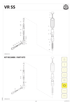
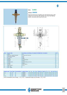
I
E
D
F
GARANZIA
I nostri prodotti sono garantiti per mesi
12 dalla consegna. La Ditta si assume la
responsabilità per tutti quei particolari
che presentassero difetti di materiale o di
lavorazione. Non è riconosciuta la garanzia
per cattiva manutenzione, anormale
impiego e per quelle parti non costruite
dalla Ditta. Le riparazioni dovranno essere
effettuate presso la fabbrica o da personale
autorizzato. Nello stesso istante in cui i
prodotti saranno manomessi da terzi, ogni
garanzia sarà ritenuta scaduta. Per ogni
verifica i prodotti dovranno essere inviati in
Porto Franco. Nel caso di effettiva necessità
di sostituzione di particolari sarà addebitato
il solo costo della mano d’opera. Per il vostro
fabbisogno di ricambi chiedete sempre
ricambi originali. In caso diverso non sarà
riconosciuta alcuna garanzia.
Numero per ordini telefonici:
(+39) 059.414.411
Numero per ordini con fax:
(+39) 059.253.505
GARANTÍA
Nuestros productos están garantizados
por 12 meses desde la fecha de la entrega.
Ninguna garantía será reconocida por malo
entretenimiento o por uso incorrecto de
los productos. Pidan siempre repuestos
originales. En caso contrario no se
reconocerá ninguna garantía.
GARANTIE
Die Firma gewährt eine Garantie von 12
Monaten, gerechnet vom Lieferdatum.
Zweck-fremder
Einsatz
und/oder
nachlässige Wartung schließen jede
Garantie aus. Im Bedarfsfall immer OriginalErsatzteile von der Firma anfordern.
Anderenfalls kann keine Garantie gewährt
werden.
GARANTIE
Nos produits sont garantis pour 12 mois
à partir de la date de livraison. Aucune
garantie ne sera reconnue, suite au
mauvais entretien ou emploi anormal des
produits. Pour tous vos besoins de pièces de
rechange, demandez toujours les rechanges
originaux. Au contraire, aucune garantie ne
sera reconnue.
Our products are guaranteed for a period
of 12 months after the date of delivery.
Warranty will not be acknowledged if the
products are not used according to the
manufacturer’s instruction or are badly
maintained. Always ask for original Spareparts, otherwise warranty will not be
acknowledged.
GB WARRANTY
Lubrificare con GRASSO Molykote G807
Lubricate with Molykote G807 GREASE
Avvitare con Loctite 5331 (Bianca)
Screw down with Loctite 5331 (White)
Lubrificare con GRASSO Molykote PG54
Lubricate with Molykote PG54 GREASE
Lubrificare con GRASSO Molykote 1000
Lubricate with Molykote 1000 GREASE
Lubrificare con GRASSO P40
Lubricate with P40 GREASE
Coppia serraggio Tolleranza +0/-10% Nm
Tightening torque tolerance +0/-10% Nm
Lubrificare con OLIO MOTORE
Lubricate with ENGINE OIL
Lubrificare con GRASSO MINERALE
Lubricate with MINERAL GREASE
Montare con PRESSA
Assemble with PRESS
Montare a caldo con RISCALDATORE
Assemble hot with HEATER
Avvitare con Loxeal 83-21 Frenafiletti FORTE (Verde)
Screw down with Loxeal 83-21 STRONG (Green)
thread sealer
Avvitare con Loxeal 55-14 Frenafiletti MEDIO (Rosso)
Screw down with Loxeal 55-14 MEDIUM (Red) thread
sealer
Avvitare con Loxeal 24-18 Frenafiletti DEBOLE (Porpora)
Screw down with Loxeal 24-18 WEAK
(Purple) thread sealer
Incollare con Loctite 454
Glue with Loctite 454
Spruzzare un velo di Molykote D-321R Spray
Spray on a light coat of Molykote D-321R
Sigillare con Loxeal 59-10
Seal with Loxeal 59-10
Sigillare con Arexons Mastice
Seal with Arexons Filler
Sigillare con Arexons MOTORSIL D
Seal with Arexons MOTORSIL D
Incollare con Biadesivo acrilico VHB-3M 4945
Glue with VHB-3M 4945 acrylic biadhesive
Avvitare con Loctite 2701 Frenafiletti FORTE (Verde)
Screw down with Loxeal 83-21 STRONG (Green)
thread sealer
Prescrizioni per Montaggio
Prescription for Assembly
ECM
UCM
Member of
ECM
UCM
AT E N Ç Ã O :
ATTENZIONE:
AT TENTION:
ACHTUNG:
AT E N C I Ó N :
AT TENTION:
160
160
l/min
42,3
42,3
gpm (US)
OUTPUT
DÉBIT
LEISTUNG
CAUDAL
PORTATA
20
20
bar
290
290
psi
PRESSURE
PRESSION
DRUCK
PRESIÓN
PRESSIONE
2-4-6
2-4-6
N. VALVES
N. ROBINETS
N. VENTILEN
N. ROBINETS
N. RUBINETTI
This manual must be read before beginning installation of the unit.
Ce livret doit être lu avant d’installer et d’employer le produit.
Das vorliegende Handbuch ist vor der Installation und dem Gebrauch des Produkts aufmerksam zu lesen.
Este manual debe ser leído antes de proceder a la instalación Y uso del producto.
Este manual deve ser lido antes de proceder à la instalação e ao uso do producto.
Il presente libretto va letto prima di procedere all’installazione ed uso del prodotto.
CONTROL UNITS
GROUPES DE COMMANDE
BEDIENUNGSARMATUREN
GRUPOS DE MANDO
GRUPPI COMANDO
1,2 ÷ 1,6
2,3 ÷ 2,7
kg
WEIGHT
POIDS
GEWICHT
PESO
PESO
TECHNICAL DATA / DONNÉES TECHNIQUES / TECHNISCHE ANGABEN
CARACTERÍSTICAS TÉCNICAS / CARACTERÍSTICAS TÉCNICAS / CARATTERISTICHE TECNICHE
Remote Control
Grupos de mando
Groupes de commande
Gruppi comando
Separate Bedienungsarmaturen
Via M.L.King,3 - 41122 Modena (Italy)
Tel. (+39) 059.414.411 - Telefax (+39) 059.253.505
E - Mail Italia: [email protected]
E - Mail export: [email protected]
ANNOVI REVERBERI S.p.A.
cod. 5754-HR
Characteristics and descriptions are not binding. -Données descriptions et illustrations n’ engagement pas le constructeur. - Angaben, Beschreibungen, und illustrationen sind nicht
verbindlich. - Noticias y ilustraciones no son empeñativas. - Os dados, descrições e ilustrações são fornecidos a título informativo e não comprometem o fabricante. - Dati, descrizioni ed
illustrazioni sono forniti a titolo indicativo e non impegativo.
(398600)
ECM - UCM
44
24
56
105
52A
51
58
57
50
50
44
84
71 118 61
111 112
117
50
1
59
119 116
71
56
24
113 114 115
3
35
48
34
106
4
120
108
104
110
13
70 109
2
SSoololo--Only
2-1
5
2-2
UN970193-DD
UN970192-DD
24
47
46
54
45
41
19
102
50 51
40 42 104
55A
43
24
48
34
35
36
37
60
38 39
34
41
55
51
50
101
97
129
96
103
30
98
100
99
49
33
32
48
31
50
53
98
51
35
34
2-3
52
2-4
UN970196-DD
UN970194-DD
44
44
11
22
23
44
18
19
20 21
14 15 16 17
24
24
12
13
10
24
2-5
UN970195-DD
MI 5754
Pos
1
2
3
4
5
10
11
12
13
14
15
16
17
18
19
20
21
22
23
24
30
31
32
33
34
35
36
37
38
39
40
41
42
43
44
45
46
47
48
49
50
51
52
53
54
55
56
57
58
59
60
61
70
71
84
96
97
98
99
100
101
102
103
104
105
106
108
109
110
111
Cod.
1547
1548
1571
1572
1348
1349
1351
1553
394850
394860
394690
390330
390341
393790
390300
390313
390323
180101
392600
640070
392580
392870
392590
392620
390291
480550
394790
394770
1040830
390440
550331
394780
394751
394741
394740
394742
394720
394730
394830
680700
394700
395530
394800
550450
391240
660170
394810
550350
550242
550210
394840
550340
550370
395000
395520
390060
395020
394870
770260
392120
880581
395390
396100
395081
395071
396110
396130
395030
394820
770130
392330
850730
1660560
1660020
480561
1660010
1660230
Descrizione
Premontaggio rubinetto
Premontaggio rubinetto
Premontaggio rubinetto
Premontaggio rubinetto
Kit valvola regolazione
Kit valvola regolazione
Corpo
Kit filtro
Corpo
Corpo
Leva
Spina
Guarnizione OR
Rondella
Molla
Rondella
Asta
Guarnizione OR
Raccordo
Guarnizione OR
Forcella
Portagomma
Portagomma
Portagomma
Guarnizione OR
Anello
Manopola
Perno
Molla
Dado
Rondella
Corpo
Pistone
Membrana
Membrana
Membrana
Valvola
Molla
Prigioniero
Vite
Corpo valvola
Forcella
Raccordo
Girello
Manometro
Guarnizione OR
Flangia
Guarnizione OR
Girello
Tubo
Flangia
Raccordo
Curva
Raccordo
Collettore
Guarnizione OR
Collettore
Tappo
Guarnizione OR
Spina
Tappo
Dado
Coperchio
Guarnizione OR
Guarnizione
Filtro
Rete esterna
Alloggiamento filtro
Staffa
Guarnizione OR
Prigioniero
Forcella
Leva
Asta
Guarnizione OR
Corpo valvola
Guarnizione OR
Description
Cock assembly
Cock assembly
Cock assembly
Cock assembly
Valve kit adjustment
Valve kit adjustment
distributore
rubinetto
rubinetto
Ø 5x2
Ø 17,5x2
Ø 13,95x2,62
Ø 10
Ø 12
Ø 19
Ø 28,25x2,62
seeger Øe 12
M6
superiore
TCEI M6x20
3/4” G
Ø 31,42x2,62
Ø 23,81X2,62
1” G
Ø 25
1” G M-M
Ø 25
Ø 20,63x2,62
Ø 23,52x1,78
1/4” G
M6
Ø 47,30x2,62
Ø 20,35x1,78
Ø 6,75x1,78
Ø 13x2
Body
Filter kit
Body
Body
Lever
Pin
O-ring
Washer
Spring
Washer
Pin
O-ring
Fitting
O-ring
Fork
Hose tail
Hose tail
Hose tail
O-ring
Ring
Knob
Hub pin
Spring
Nut
Washer
Body
Piston
Diaphragm
Diaphragm
Diaphragm
Valve
Spring
Stud
Screw
Valve body
Fork
Fitting
Ring nut
Pressure gauge
O-ring
Flange
O-ring
Ring nut
Pipe
Flange
Fitting
Elbow
Fitting
Suction fitting
O-ring
Suction fitting
Plug
O-ring
Pin
Plug
Nut
Cover
O-ring
Gasket
Filter
External grid
Filter housing
Bracket
O-ring
Stud
Fork
Lever
Pin
O-ring
Valve body
O-ring
Q.ty
Note
1
1
1
1
1
1
1
1
1
1
4
5
4
4
4
4
4
5
4
4
4
4
4
4
5
1
1
1
1
16
12
1
1
1
1
1
1
1
8
1
1
5
1
1
1
3
1
4
2
2
1
1
1
2
1
1
1
1
1
1
2
1
1
1
2
1
1
1
1
1
8
1
1
1
2
1
1
Uscita /Outlet ø 12
Uscita /Outlet ø 12
Uscita /Outlet ø 12
Uscita /Outlet ø 12
Pos
112
113
114
115
116
117
Cod.
1660541
1660050
1660090
1660080
393790
1660060
1660100
1660110
1660120
119 1660140
120 1660551
129 396590
18
Descrizione
Molla
Valvola
Molla
Guida
Rondella
Flangia
Sede ROSSO
Sede ARANCIO
Sede BLU
Rondella
Guarnizione OR
Ø 7x2
Tappo
3/8” G
Description
Spring
Valve
Spring
Guide
Washer
Flange
Seat
Seat
Seat
Washer
O-ring
Plug
Q.ty
1
1
1
1
1
1
1
1
1
1
1
1
sp_ecm_ucm.pdf
ECM - UCM
Note
Inox
Vedi/See
Vedi/See
Vedi/See
Viton
Inox
Inox
C10
NBR
Desmopan
Viton
C6
Inox
Nota: Le quantità espresse sono riferite alla versione a 4 rubinetti
Note: The quantities refer to the 4 valves version
0-24 bar
Per/For: AR 70 bp-AR 80bp-AR120/140bp
Per/For: AR 115-135 bp - AR 125-145 bp
Per/For: AR 160 bp
Per/For: AR 60 bp
Per/For: AR 100 bp - AR 120 bp
Per/For: AR 150 bp
5782 FOGLIO ILLUSTRAZIONE KIT 1973
Inox
C3
Inox C10
KIT 2346
KIT 2339
OR
O-Rings
Pronto intervento
Maintenance repair
Viton
Pos.
Q.ty
Pos.
Q.ty
Pos.
Q.ty
Pos.
Q.ty
5
7
5
5
3
4
1
1
1
1
109
111
120
2
1
1
C10
14
19
21
24
48
50
58
61
97
103
12
14
18
24
38
39
44
51
55
58
2
5
2
5
1
1
1
1
1
1
60
61
98
106
109
113
115
120
1
1
2
1
2
1
1
1
Viton
DESCRIZIONE E MODO D’USO
Il gruppo comando ECM-UCM serve per la regolazione della pressione di lavoro negli impianti diserbanti e per la distribuzione del
liquido negli impianti stessi.
I
DESCRIPCIÓN Y FORMA DE EMPLEO
El distribudor ECM-UCM sirve para la regulación de la presión de
trabajo en los equipos herbicidas y para la distribución de liquido
en el propio equipo.
I richiami numerici fanno riferimento al disegno esploso del prodotto.
E
GEBRAUCHSANWEISUNG
Die Präzisions-Regelarmatur ECM-UCM ist Baukastensystem ausgelegt.
Hauptbestandteil ist das Zentralventil (43-110) aus korrosionsfestem,
Edelkun-ststoff. Die Abdichtung aller Anbauteile erfolgt durch O-Ringe.
Las indicaciones numéricas se refieren al gráfico de despiece del
producto.
D
DESCRIPTION ET MODE D’EMPLOI
Le groupe de commande sert pour le réglage de la pression de travail
dans l’emploi du désherbant et pour la distribution du liquide dans
les circuits.
Die numerischen Verweise beziehen sich auf die Explosionszeichnung des Produkts.
F
DESCRIPTION AND USE
The ECM-UCM is a control unit for the regulating working pressure in the field crop sprayers and for the liquids distribution in
the same systems.
Les renvois numériques font référence au dessin éclaté du produit.
GB
Numbers refer to the exploded view of the product.
TRABAJO
En el transcurso de las varias fases de trabajo se podrán cerrar
parcialmente algunos sectores de la barra, actuando sobre el
respectivo grifo mediante la palanca (12).
El ECM-UCM en estos casos no dará lugar a variaciones de presión
importantes, como para modificar la cantidad de liquido distribuido por hectárea.
En el caso de cierre total del flujo de liquido a la barra y de puestas a cero de la presión bastara con levantar la palanca (106) de
posición baja a la posición alta (UCM).
Al final de cada tratamiento es convenientes proceder a la limpieza de la instalación a través de la circulación de agua limpia.
Si el ECM-UCM esta dotado de filtro, limpiar el mismo diariamente destornillando para ello la tapa del filtro.
ISTRUZIONI PER LA SICUREZZA
È necessario conservare con cura il presente manuale, leggere e
rispettare le seguenti istruzioni per la sicurezza:
• Non utilizzare il prodotto con fluidi infiammabili o aventi caratteristiche non compatibili con il corretto funzionamento del
prodotto stesso.
• L’istallazione del prodotto deve essere effettuata da personale
qualificato.
LAVORO
Nel corso delle varie fasi di lavoro si potrà chiudere parzialmente alcuni settori di barra agendo sul rispettivo rubinetto mediante la leva
12. L’ECM-UCM in questi casi non darà luogo a variazioni di pressione importanti tali da modificare la quantità di liquido per ettaro.
Per chiudere totalmente l’afflusso del liquido alla barra e togliere
la pressione alla barra basterà sollevare la leva 106 dalla posizione I
alla posizione 0 (solo UCM).
Quando il risucchio antigocciolamento è montato esso sarà automaticamente inserito alzando la leva 106 (UCM). Ad ogni fine
trattamento è buona norma procedere ad una pulizia dell’impianto
tramite la circolazione di acqua pulita. Se l’ECM-UCM è munito di
filtro, pulire lo stesso giornalmente, tramite lo svitamento del coperchio del filtro stesso.
REGOLAZIONE DELLA PRESSIONE
La regolazione della pressione di lavoro si ottiene mediante la manopola 31.
Girando in senso orario aumenta, in senso antiorario diminuisce. La
regolazione della pressione va eseguita con la leva 106 in posizione
“0” e con i rubinetti di alimentazione barra in posizione aperta “I”.
L’apertura e chiusura dei rubinetti barra si ottiene mediante la manovra della leva 12.
La regolazione della pressione è bene farla prima delI’inizio del lavoro con acqua, verificando che tutte le giunzioni ed i vari raccordi
non abbiano perdite.
Tale regolazione dovrà essere effettuata con la presa di forza a 540
giri max. o comunque alla velocità di rotazione corrispondente alla
velocità di lavoro possibile.
COLLEGAMENTO TUBI
Al raccordo 55 o 52 deve essere collegato il tubo che arriva dalla
pompa mentre al raccordo 55A o 52A va collegato il tubo di ritorno
che riporta in serbatoio il liquido non impiegato. Ai raccordi 23 vanno collegati i tubi di alimentazione della barra in numero pari alle
sezioni della barra stessa.
RACCORDEMENT DES TUYAUX
Au raccord (55 ou 52) doit être branché le tuyau qui arrive de la pompe
et au raccord (55A ou 52A) doit être branché le tuyau de retour qui restitue le liquide non-utilisé dans la cuve. Aux raccords 23 doivent être
branchés les tuyaux d’alimentation de la barre égaux au nombre des
sections de la barre même.
CONEXIÓN TUBOS
En el empalme (55 o 52) debe conectarse el tubo que llega desde
la bomba mientra que en el empalme (55A o 52A) va conectado
el tubo de retorno que lleva al deposito el liquido sobrante.
En los empalmes (23) van conectados los tubos de alimentación
de la barra, en número igual a las secciones de la misma.
HOSES CONNECTION
The pressure hose from the pump is connected to the fitting 55 or
52 while the return hose to tank is connected to the fitting 55A
or 52A.
Boom connection hoses are connected to the fitting 23 depending
on the number of boom sections.
BEDIENUNG DER SCHNELLSCHLUSSVENTILEN (12)
OFFEN = Ventilhebel senkrecht nach oben.
ZU = Ventilhebel senkrecht nach unten.
Die Präzisionsarmatur ECM-UCM nimmt Druckschwankungen die sich
durch das Abstellen einzelner Rohrteilbreiten ergeben, sehr gut auf
(Gleichdruckeffekt). Das GLYZERINMANOMETER (47) zeigt den eingestellten Betriebsdruck an. Das Manometer ist ein empfindliches Messinstrument uns muß jährlich überprüft werden. Zeigt das Manometer
falsch an, können durch falsche Ausstossmengen erhebliche Folgenschaden auftreten. Wenn vorhanden, Druckleitungsfilter mindestens
täglich reinigen.
Achtung: bei Aufbewahrung der Armatur in nicht frostsicheren Räumen ist das Wasser aus der Armatur und dem Druckleitungsfilter (wenn
vorhanden) abzulassen. Nach der Spritzarbeit Armatur mit Wasser
reinigen.
INSTRUCCIONES PARA LA SEGURIDAD
Es necesario conservar con cuidado el presente manual, leer y
respetar las siguientes instrucciones para la seguridad:
• No utilizar el producto con fluidos inflamables o que tengan
características no compatibles con el correcto funcionamiento
del producto.
• La instalación del producto debe ser efectuada por personal
especializado.
REGULACIÓN DE PRESIÓN
Le regulación de la presión de trabajo se obtiene mediante la
maneta (31).
Girando en el sentio de las manecillas del reloj aumenta, en sentido contrario de las manecillas del reloj disminuye.
La regulación de las presión se obtiene con la palanca (106) en
posición baja y con los grifos de alimentación de la barra abiertos.
La apertura y cierre de los grifos de la barra se obtienen maniobrando la palanca (12). La regulación de la prisión es conveniente hacerla antes del inicio del trabajo, con agua. Verificando que
ni las juntas ni los diferentes ampalmes tengan ninguna fuga.
Dicha regulación deberá efectuarse con la toma de fuerza a 540
r.p.m. o bien a la velocidad de rotación correspondiente a la velocidad de trabajo escogida.
SICHERHEITSANLEITUNGEN
Vorliegendes Handbuch sorgfältig aufbewahren und folgende
Sicherheitsanleitungen aufmerksam lesen und beachten:
• Produkt nicht mit entzündbaren oder sonstigen Flüssigkeiten
verwenden, deren Eigenschaften mit einem einwandfreien
Betrieb des Produkts nicht vereinbar sind.
• Die Produktinstallation ist von qualifiziertem Fachpersonal vorzunehmen.
BEDIENUNG
Die Druckregulierung von 0-20 bar erfolgt am Drehgriff (31): Rechtsdrehen = Druckerhöhung; Linksdrehen = Druckminderung
Druckregulierung darf nur in der ElN-Stellung erfolgen. Das EIN- und
AUS-Schalten der Armatur erfolgt am Schalthebel (106).
AUS-Stellung = Senkrechte Stellung nach oben.
Die Flüssigkeit fließt drucklos direkt über den Rücklauf ins Fass zurück
und der Zulauf zu den Schnellschlussventilen ist geschlossen (nodrop-Effekt). Die Rücksaugvorrichtung (wenn vorhanden) wird in der
Stellung ‘AUS’ automatisch eingeschaltet. ElN-Stellung = Senkrechte
Stellung nach unten. Der Zulauf zu den Schnellschluss-ventilen (12) ist
offen. Die Flüssigkeit fließt mit dem eingestelltem Druck zu den Schnellschlussventilen.
ANSCHLUSS DER SCHLAUCHE
Der Druckschlauch (55 oder 52) von der Pumpe wird an der Unterseite
des Zentralventils bzw. bei vorhandenem Druckleitungsfilter an diesem
angebracht. Der Rücklaufschlauch zum Fass wird an der Rückseite der
Armatur montiert (55A oder 52A). Verbindunsschläuche zum Spritzrohr
sind durch Schnellsteckverbindungen (23) am Druckregler angeschlossen. Bei vorhandener Rücksauhvorrichtung darf am Rücklaufschlauch
(55A oder 52A) keine Ruhrdüse montier werden.
RÉGLAGE DE LA PRESSION
Le réglage de la pression de travail s’obtient par l’intermédiaire de la
poignée 31. En la tournant dans le sens des aiguilles d’une montre on
augmente la pression et dans le sens inverse on la diminue.
Le réglage de la pression doit être réalisé avec le levier (106) en position “0” et avec les robinets d’alimentation de la barre en position ouverte. L’ouverture et la fermeture des robinets de la barre s’obtiennent
par l’intermédiaire du levier (12). Le réglage de la pression doit être
fait avant de commencer le travail avec l’eau, en vérifiant que les joints
et les différents raccords n’ont pas de pertes. Ce réglage devra être effectué avec la prise de force à max. 540 tours, ou de toute façon à la
vitesse de rotation correspondant à la vitesse de travail possible.
INSTRUCTIONS DE SÉCURITÉ
Conserver ce manuel avec le plus grand soin. Lire et respecter les
instructions de sécurité ci-dessous:
• Ne pas utiliser le produit avec des fluides inflammables ou ayant
des caractéristiques incompatibles avec le fonctionnement correct du produit lui-même.
• L’installation du produit doit être effectuée par un personnel
qualifié.
LE TRAVAIL
Au cours de différentes phases de travail on pourra fermer partiellement quelques sections de barre en agissant sur le respectif robinet
par l’intermédiaire du levier. Dans ces conditions, l’ECM-UCM ne donnera pas lieu à des variations de pression importantes qui peuvent
modifier la quantité de liquide à l’hectare. Pour la fermeture totale de
l’afflux du liquide à la barre , il suffira de soulever le levier 106 de la
position “I” à la position “0” (seulement UCM). Quand le remous dégoulinement est assemblé il sera inséré automatiquement soulevant
le levier 106 (UCM). Après la fin de chaque traitement il sera nécessaire
de procéder à un nettoyage du circuit par l’intermédiaire de la circulation d’eau propre. Si l’ECM-UCM est muni d’un filtre, nettoyeur le
même quotidiennement, par le dévissage de la chape du filtre même.
PRESSURE REGULATION
Pressure is regulated by hand knob 31:
clockwise = higher pressure;
anticlockwise = lower pressure.
Pressure is regulated with the lever 106 in the “0” position and
with the boom feed in open position.
The boom cocks opening and closing is obtained by lever control
12. The pressure regulating has to be done before the working beginning with water, verifying that all the joints and the different
fittings have no leaks.
This regulation should be carried out with the power take-off to
max 540 r. or however to the rotation speed corresponding to the
possible working speed.
WORKING
During the different working phases some boom sections could
partially be closed using the respective cock through lever 12 . The
ECM-UCM, in these cases, should not give pressure variations so
important to modify the liquid quantity per hectare.
To close totally the liquid inflow to the boom and remove the pressure to the boom it will be sufficient to rise the lever 106 from “I”
position to “0” position (only UCM).
When the anti-dripping piping is mounted it automatically will be
inserted rising the lever 106 (UCM).
After each treatment it is a good rule to proceed with system
cleaning through the clean water circulation.
If ECM-UCM is c/w filter, clean the same daily, through the cover
unscrewing of the same filter.
SAFETY INSTRUCTIONS
This manual must be stored carefully. Read and follow the following safety instructions:
• Do not use the unit with flammable liquids, or liquids with
characteristics not compatible with the correct functioning of
the unit.
• The installation of the unit must be carried out by qualified staff.
Scaricare