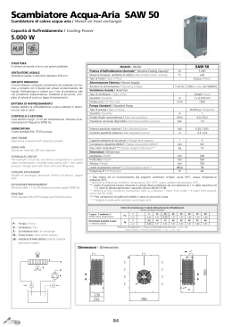
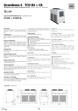
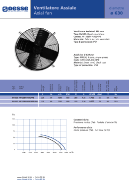
M I
N
I
C O O L E R
SERVICE MANUAL MANUALE DI ASSISTENZA
English
Italiano
Network Power
Cod. 272658
Rev. 07.07.2003
Issued by T.D.Service
Liebert HIROSS
is a division of
Emerson
Caution
It is recommended that:
the manual is retained for the entire service life of the machine;
the user reads the manual carefully before carrying out any operations on the machine;
the machine is used exclusively for the purpose for which it is intended; incorrect use of the machine shall release the manufac
turer from any liability.
This manual has been prepared to enable the end-user to carry out only those operations that can done with the panels closed.
Any operation that requires the opening of doors or equipment panels must be carried out only by skilled personnel.
To enable the operator to work in safety conditions, it is necessary to cut the conditioner off, opening the switches BR12 and BR6
on the cabin.
This operation must always be carried out to eliminate hazards during the maintenance (electric shocks, burns, automatic restar
ting, moving parts and remote control).
For identifying the unit (model and serial no.) in case of need for service or spare parts, read the identification label placed on the
outside and inside of the unit.
IMPORTANT:
This manual may be subject to modification; for complete and up-to-date information
the user should always consult the manual supplied with the machine.
Index
1 - Preliminary operations . . . . . . . . . . . . . . . . . . . . . . . . . . . . . . . . . . . . . . . . . . . . . . . . . . . . . . . . . . . . . . . . . . 1
1.1 -
Foreword . . . . . . . . . . . . . . . . . . . . . . . . . . . . . . . . . . . . . . . . . . . . . . . . . . . . . . . . . . . . . . . . . . . . . . . . . . . . . . 1
1.2 -
Operating limits . . . . . . . . . . . . . . . . . . . . . . . . . . . . . . . . . . . . . . . . . . . . . . . . . . . . . . . . . . . . . . . . . . . . . . . . . 1
1.3 -
Inspection . . . . . . . . . . . . . . . . . . . . . . . . . . . . . . . . . . . . . . . . . . . . . . . . . . . . . . . . . . . . . . . . . . . . . . . . . . . . . . 1
1.4 -
Transport . . . . . . . . . . . . . . . . . . . . . . . . . . . . . . . . . . . . . . . . . . . . . . . . . . . . . . . . . . . . . . . . . . . . . . . . . . . . . . 1
2 - Installation . . . . . . . . . . . . . . . . . . . . . . . . . . . . . . . . . . . . . . . . . . . . . . . . . . . . . . . . . . . . . . . . . . . . . . . . . . . . 1
2.1 -
Installation note . . . . . . . . . . . . . . . . . . . . . . . . . . . . . . . . . . . . . . . . . . . . . . . . . . . . . . . . . . . . . . . . . . . . . . . . 1
2.2 -
Site preparation . . . . . . . . . . . . . . . . . . . . . . . . . . . . . . . . . . . . . . . . . . . . . . . . . . . . . . . . . . . . . . . . . . . . . . . . . 1
2.2.1 - Optional floor fixing . . . . . . . . . . . . . . . . . . . . . . . . . . . . . . . . . . . . . . . . . . . . . . . . . . . . . . . . . . . . . . . . . . . . . . . . 1
3 - Electrical connections . . . . . . . . . . . . . . . . . . . . . . . . . . . . . . . . . . . . . . . . . . . . . . . . . . . . . . . . . . . . . . . . . . . 1
3.1 -
Electrical connections and configuration
................................................... 1
3.2 -
Remote switch . . . . . . . . . . . . . . . . . . . . . . . . . . . . . . . . . . . . . . . . . . . . . . . . . . . . . . . . . . . . . . . . . . . . . . . . . . 1
4 - Start-up . . . . . . . . . . . . . . . . . . . . . . . . . . . . . . . . . . . . . . . . . . . . . . . . . . . . . . . . . . . . . . . . . . . . . . . . . . . . . . 2
4.1 -
First start-up (or after a long halt) . . . . . . . . . . . . . . . . . . . . . . . . . . . . . . . . . . . . . . . . . . . . . . . . . . . . . . . . 2
4.2 -
Start-up with low outside temperature . . . . . . . . . . . . . . . . . . . . . . . . . . . . . . . . . . . . . . . . . . . . . . . . . . . . . 2
4.3 -
Acknowledge the machine regular switching-on. . . . . . . . . . . . . . . . . . . . . . . . . . . . . . . . . . . . . . . . . . . . . . 2
4.4 -
Operating unit and stand-by unit . . . . . . . . . . . . . . . . . . . . . . . . . . . . . . . . . . . . . . . . . . . . . . . . . . . . . . . . . 2
5 - Operation . . . . . . . . . . . . . . . . . . . . . . . . . . . . . . . . . . . . . . . . . . . . . . . . . . . . . . . . . . . . . . . . . . . . . . . . . . . . . 2
5.1 -
Active cooling (DX) . . . . . . . . . . . . . . . . . . . . . . . . . . . . . . . . . . . . . . . . . . . . . . . . . . . . . . . . . . . . . . . . . . . . . 2
5.1.1 - Adjustment of the condenser fan speed (Variex) . . . . . . . . . . . . . . . . . . . . . . . . . . . . . . . . . . . . . . . . . . . . . . . . . . 3
5.2 -
Haeting (optional) . . . . . . . . . . . . . . . . . . . . . . . . . . . . . . . . . . . . . . . . . . . . . . . . . . . . . . . . . . . . . . . . . . . . . . . 3
5.2.1 - Safety thermostat . . . . . . . . . . . . . . . . . . . . . . . . . . . . . . . . . . . . . . . . . . . . . . . . . . . . . . . . . . . . . . . . . . . . . . . . . . 3
5.3 -
Cooling in Freecooling . . . . . . . . . . . . . . . . . . . . . . . . . . . . . . . . . . . . . . . . . . . . . . . . . . . . . . . . . . . . . . . . . . . 3
5.4 -
Active cooling with fresh air . . . . . . . . . . . . . . . . . . . . . . . . . . . . . . . . . . . . . . . . . . . . . . . . . . . . . . . . . . . . . . . 3
5.5 -
Emergency cooling . . . . . . . . . . . . . . . . . . . . . . . . . . . . . . . . . . . . . . . . . . . . . . . . . . . . . . . . . . . . . . . . . . . . . . 3
6 - Microprocessor control . . . . . . . . . . . . . . . . . . . . . . . . . . . . . . . . . . . . . . . . . . . . . . . . . . . . . . . . . . . . . . . . . . 3
7 - Calibrations . . . . . . . . . . . . . . . . . . . . . . . . . . . . . . . . . . . . . . . . . . . . . . . . . . . . . . . . . . . . . . . . . . . . . . . . . . . 4
8 - Maintenance . . . . . . . . . . . . . . . . . . . . . . . . . . . . . . . . . . . . . . . . . . . . . . . . . . . . . . . . . . . . . . . . . . . . . . . . . . . 4
8.1 -
Routine maintenance . . . . . . . . . . . . . . . . . . . . . . . . . . . . . . . . . . . . . . . . . . . . . . . . . . . . . . . . . . . . . . . . . . . . 4
8.1.1 - Air filtes . . . . . . . . . . . . . . . . . . . . . . . . . . . . . . . . . . . . . . . . . . . . . . . . . . . . . . . . . . . . . . . . . . . . . . . . . . . . . . . . . . 4
English
8.1.2 - Fans . . . . . . . . . . . . . . . . . . . . . . . . . . . . . . . . . . . . . . . . . . . . . . . . . . . . . . . . . . . . . . . . . . . . . . . . . . . . . . . . . . . . . 4
8.1.3 - Electric circuit . . . . . . . . . . . . . . . . . . . . . . . . . . . . . . . . . . . . . . . . . . . . . . . . . . . . . . . . . . . . . . . . . . . . . . . . . . . . . 4
8.1.4 - Refrigeration circuit . . . . . . . . . . . . . . . . . . . . . . . . . . . . . . . . . . . . . . . . . . . . . . . . . . . . . . . . . . . . . . . . . . . . . . . . 4
8.2 -
Extraordinary maintenance . . . . . . . . . . . . . . . . . . . . . . . . . . . . . . . . . . . . . . . . . . . . . . . . . . . . . . . . . . . . . . . 4
8.2.1 8.2.2 8.2.3 8.2.4 -
8.3 -
Check of the system vacuum and leaks. . . . . . . . . . . . . . . . . . . . . . . . . . . . . . . . . . . . . . . . . . . . . . . . . . . . . . . . . .
Refrigerant charge operations . . . . . . . . . . . . . . . . . . . . . . . . . . . . . . . . . . . . . . . . . . . . . . . . . . . . . . . . . . . . . . . .
Overheating calculation . . . . . . . . . . . . . . . . . . . . . . . . . . . . . . . . . . . . . . . . . . . . . . . . . . . . . . . . . . . . . . . . . . . . .
Features of the refrigerant fluid . . . . . . . . . . . . . . . . . . . . . . . . . . . . . . . . . . . . . . . . . . . . . . . . . . . . . . . . . . . . . . .
4
4
4
4
Unit dismantling . . . . . . . . . . . . . . . . . . . . . . . . . . . . . . . . . . . . . . . . . . . . . . . . . . . . . . . . . . . . . . . . . . . . . . . . 5
English
1 - Preliminary operations
ATTENTION
1.1 - Foreword
Also refer to the manual for the microprocessor control
Microface supplied with the unit.
1.2 - Operating limits
The units are provided for operating within the working li
mits (Tab. 1).
These limits are referred to new machines that have been
correctly installed or that have been correctly serviced.
Tab. 1 - Operating limits
230 V ac ± 10% / 1 / 50Hz
48 ± 20% V dc
from:
-20°C
to:
+45°C
Inside conditions with
running compressor
from:
20°C, 30% R.H.
to:
40°C, 40% R.H.
Storing conditions
from:
-40°C, 5% R.H.
to:
55°C, 90% R.H.
2.2.1 - Optional floor fixing
The machine can be fixed to the floor.
The same fixing nuts used for fastening the machine to the
pallet for the transport are to be used in this case, too.
(*) Max. outer temperature referred to the inner air temperature = 35C.
The warranty clauses are no longer valid for any damage or
malfunction that may occur during or due to operation
outside the application values.
1.3 - Inspection
On receiving the equipment immediately inspect its
condition; report any damage to the transport company at
once.
1.4 - Transport
The machine can be accessed for every intervention on the
control system and/or for routine maintenance from its
outer side, removing the freecooling front grille and panel
(see fig. 1).
It is necessary to arrange a suitable opening on the wall of
the shelter where the machine is installed.
The holes for the treated air duct and for the condensate
drain pipe, placed under the machine are to be drilled
following the drawing in Fig. 1.
HCS4U
O t id conditions
Outside
diti
(*)
2.1 - Installation note
2.2 - Site preparation
Model
P
Power
supply
l
The unit ALWAYS requires a direct current supply equal
to 48 V d.c. voltage. If this supply is temporarily not
available at the installation, it is recommended to use a
portable voltage rectifier, or, as alternative, auxiliary
batteries with suitable capacity (check the most suitable
source in details).
Always keep the unit vertically upright.
If possible, transport the unit using a fork lift truck;
otherwise use a crane with belts or cables, avoiding
pressure on the top edges of the packing.
Unpack the unit as close as possible to its installation
position. Once unpacked, avoid stress being
transmitted to its internal components.
3 - Electrical connections
Before performing any operations on the electric parts,
make sure that:
all electrical components are undamaged;
all terminal screws are tight;
the supply voltage and frequency are as indicated on
the unit;
3.1 - Electrical connections and configuration
(Read the wiring diagram supplied with
the unit)
2 - Installation
The unit is equipped with condensate water drain system.
The drain line must therefore be suitably connected with
the collection/discharge system of the shelter, so as to
prevent the presence of water inside it.
The electric supply must be connected with the
terminal board inside the connector block on the unit
roof.
At this point make the electrical connections. Carefully
follow the numeration shown on the terminal board
and in the enclosure Wiring diagram.Connect the
ground cable to the yellow-green temrinal.
To connect 2 or more units installed, use the HIROBUS
cable (supplied with the unit) by connecting it as shown
in the wiring diagram.
See the Microface manual for the configuration of the
Stand-by units.
3.2 - Remote switch
The unit is directly connected with the supply mains. It is
recommended to use a remote switch/knife switch to
power and cut the machine off.
English
1
Tab. 2 - Standard electrical characteristics
Components with power supply 230V/1Ph/50Hz
Condenser fan
(n°2 fans)
OA
[A]
1.15
FLA
[A]
1.65
LRA
[A]
1.85
Absorbed power
[kW]
0.52
OA
[A]
7.7
FLA
[A]
15
LRA
[A]
62
Absorbed power
[kW]
1.6
OA
[A]
2.81
Absorbed power
[W]
136
Compressor
Components with power supply 48Vd.c.
Evaporator fan
OA: Operating Ampère;
FLA: Full Load Ampère;
LRA: Locked Rotor Ampère.
Tab. 3 - Protection switches and cable size
Power supply
Protection switch
Cables sizing
[mmq]
230V/1Ph/50Hz
6A (condenser fan)
16A (compressor)
Nr.2 x 4 +T x 4
48Vd.c.
6A
Nr.2 x 2.5
4 - Start-up
4.1 - First start-up
(or after a long halt)
Before starting the air conditioner do check if the power
supply voltage and frequency comply with those indicated
on the identification plate of the unit.
After that, the conditioner can be started setting the
switches to the ON position.
Check the electrical input of all components and compare
it with the data shown in the Tab. 2. Check that there are
no active alarms; wait until the system reaches the
standard operation and then make the following checks:
check that the fans are working correctly;
make sure that the temperature is guaranteed and the
compressor works when required;
make sure that the speed adjuster of the fan of the
condensing section is correctly calibrated and controls
the fan operation (Chapt. 7).
4) For units connect in a network only: if the system
requires so, the refrigerating compressor is switched
on after 2 further minutes.
4.4 - Operating unit and stand-by unit
For the installation of two combined units, with
alternated" operation it is necessary:
1) to identify the unit no. 2 moving the jumper on the
control board;
2) to connect the two control boards through a 6-way
shielded Hirobus cable;
3) set the parameter number of connected units" at 2 on
the machine 1;
4) set the number of units that must be in stand-by ( = 1
)
5) enable the cascade function at yes".
Refer to the control handbook for every detail on these
settings.
5 - Operation
The unit operation is completely automatic.
After switching-on, the evaporator fan (fig. 2 - pos. 5) is
always on.
The control system measures three temperature values
through three probes placed:
on the recirculating air inlet (t1);
on the air delivery (t2);
on the outer air inlet (t3).
According to the values measured by the three probes and
to the conditions of the power supply, the control sets the
conditioner for the air treatment, in five modes:
Active cooling (DX)
Heating
Cooling in freecooling
Active cooling with fresh air
Emergency cooling
5.1 - Active cooling (DX)
The machine cools the room inner air to be conditioned,
sucking it from the recirculation inlet.
T1
4.2 - Start-up with low outside temperature
In case of low outside temperature (<0C), the unit
start-up is helped by the lag time of the low pressure
alarm, within which the pressures in the refrigerating
circuit reach the standard operation values.
4.3 - Acknowledge the
switching-on.
machine
regular
If all the preliminary installation and connection steps of
the machine have been correctly carried out, when the
machine is powered for the first time the following can be
noted:
1) the control display is activated;
2) after about 30 sec. the evaporator fan switches on;
3) the control unit display shows the temperature value
measured by the probe t1, alternated with the writing
t1";
2
T3
T2
The compressor is started up from the control when the
sucted air temperature (sensor T1) of the room to be con
ditioned exceeds the preset value. The intake air from the
fan (Fig. 2 pos. 5) goes immediately through thre filter
and then the evaporator.
The conditioned air is conveyed into the conditioned
room through the discharge opening.
The heat taken from the room and the one generated by
the conditioner motor operation are disposed through the
condenser, which is hit, thanks to the condenser fans (Fig.
2 pos. 8), by the outside air. The fan operation is conti
nuously controlled (by Variex Par. NO TAG) as a function
of the condensing pressure.
An appropriate metallic filter protects the fin coil.
English
5.1.1 - Adjustment of the condenser fan speed (Variex)
This device ensures the correct unit operation even with
very low outer temperature (between -10°C and -25°C).
A sensor is positioned so as to detect constantly the
condensing pressure of the refrigerating gas. On the basis
of this information, an electronic device (Variex) adjusts
the fan rotation speed in order to keep the condensing
pressure within the allowed values. In this way, besides
optimizing the compressor operation, you can have a
remarkable reduction of the sound pressure level (mainly
during the night), an easier start-up of the compressor at
low temperatures and some energy saving.
For the calibration of the speed adjuster refer to chapter 7.
5.2 - Haeting (optional)
The machine heats the room inner air to be conditioned,
sucking it from the recirculation inlet.
When the expected conditions occur, the servomotor
modulates the opening of the inner movable damper that,
during the DX cooling, separated the circulation of the
recirculating air from the outer air, cooling the condenser.
In this way the outer air, sucked by the fan, flows in the
environment and exits through the opening in the
condensing section.
The damper opening extent is determined according to
the chosen set point value and to the temperature of the
inlet air (see chapt. 6).
5.4 - Active cooling with fresh air
The machine cools the inner environment taking air from
outside and cooling it.
When the expected conditions occur, the servomotor
modulates the opening of the inner movable damper.
The outer air, sucked by the fan, flows in the environment
and exits through the opening in the condensing section.
T1
T1
T3
T2
T2
The electric heater is started by the control system (Fig. 2 pos. 13) when the sucked air temperature (sensor T1) of
the room to be conditioned is lower than the presdet value.
5.2.1 - Safety thermostat
The safety thermostat cuts the heater off, should it reach a
temperature over 85°C.
It has a manual reset.
It can be accessed after removing the electric board panel
(see fig.2).
5.3 - Cooling in Freecooling
The machine cools the environment thanks to the direct
inlet of fresh outer air.
The damper opening extent is determined according to
the chosen set point value and to the temperature of the
inlet air (see chapt. 6).
5.5 - Emergency cooling
The emergency cooling function (EFC) is activated when
the main supply (230 V/1 Ph/50 Hz) is cut off.
The evaporator fan, the freecooling damper control and
motor are supplied by the same power source at 48 V dc.
If the main ac supply is cut off, the parts supplied by 48 V
dc go on operating. The condenser fan and compressor
remain off.
The air circulation inside the site is ensured and the
freecooling is activated as soon as the suitable conditions
occur.
T1
T3
T2
6 - Microprocessor control
The machine is equipped with Microface microprocessor
control for the complete monitoring of all the unit
operating parameters. Refer to the enclosed handbook for
the used settings and configurations.
English
3
7 - Calibrations
The air conditioner has already been factory-tested
and calibrated as described here below.
For the MICROFACE calibrations refer to the
relevant manual (to avoid wrong operations do not use
temperature and rel. humidity set points/proportional
bands which differ excessively from the standard
settings).
COMPONENT
CALIBRATION
Low pressure switch (LP)
STOP
START
: 0.7 bar
: 1.2 bar
High pressure switch (HP)
STOP
START
: 24 bar
: 17.5 bar
Fan speed adjuster (variex)
SET.
P BAND
: 18.8 bar
: 3.8 bar
8 - Maintenance
Cut the unit off before performing any maintenance operations
The Maintenance Program described below should be car
ried out by a skilled technician, preferably working under a
maintenance contract..
8.1 - Routine maintenance
Maintenance program - Monthly check
8.1.1 - Air filtes
Check the air filter conditions; if necessary, clean or
replace the filter. In very dusty environments perform this
check more frequently.
8.1.2 - Fans
Check that the fan motor rotates freely without any abnor
mal noise, and ensure that the bearings are not running
hot. Also check the current absorption.
8.1.3 - Electric circuit
Check the power supply on all phases. Make sure that all
electrical connections are tight.
8.1.4 - Refrigeration circuit
Check the evaporating pressures (to be done by a refrige
ration technician).
8.2 - Extraordinary maintenance
8.2.1 - Check of the system vacuum and leaks.
Note:
Before proceeding, recover all the refrigerant, according
to the local laws.
1) Switch the unit off (outer switch on OFF).
2) Remove the fornt panels.
3) Connect a high efficiency vacuum pump to the needle
valves (Schräder) on the gas and liquid lines; also ar
range a connection with a nitrogen bottle.
4) Load the circuit with nitrogen (7 bar/700 kPa). Find
possible leaks in the circuit by soapy water or other spe
cific product (foaming agents), and repair as necessary.
5) Drain the circuit by a vacuum of 0.3 mbar absolute.
4
6) After 3 hours check not to have exceeded 1.3 mbar ab
solute; this condition ensures a humidity lower than 50
ppm inside the system. If the vacuum is not kept there
are still leaks; repeat the operations from point 4.
8.2.2 - Refrigerant charge operations
After having eliminated the humidity from the
refrigerating circuit (see 8.2.1), proceed as follows:
1) make sure all the unit components are in operating or
der.
2) Power the unit.
3) By a charge hose, connect a refrigerant bottle with the
valve placed on the liquid line downstream the thermal
expansion valve. Drain the substances that cannot be
condensed from the hose.
4) Start the compressor.
5) Charge the circuit slowly until the sight glass is clear.
The charge operation can be considered finished
when, keeping the condensation temperature at a
steady level (~50°C, if necessary partially clog the
condensing coil), no more bubbles appear for at least
ten minutes. Check if the overheating in these
conditions is 7÷8 degrees..
8.2.3 - Overheating calculation
With the unit operating in standard conditions, measu
re the temperature of the suction line in the point whe
re the bulb of the thermal expansion valve is fastened.
Detect the evaporation pressure gauge temperature
from a pressure gauge placed on the compressor suc
tion.
Subtract the just obtained temperature value from the
one measured in the first point. The difference is the
overheating value.
8.2.4 - Features of the refrigerant fluid
The machine refrigerating circuit is charged with
refrigerant fluid R134a.
This fluid is harmless for the ozone layer.
Polyester lubricant oil, type MOBIL EAL ARTIC 22CC,
also flows in the refrigerating circuit.
The refrigerant fluid R134a is not compatible with the
mineral oils usually adopted in other refrigerating
installations (e.g. circuits operating with R22).
(For further info ask for the complete technical sheet).
English
Tab. 4 - R134a refrigerant charge
HCS4U
1,35 kg
The oil to be used for topping up is MOBIL EAL ARTIC
22CC; if it is not available, use an oil with the same
features (Tab. 5).
NEVER MIX INCOMPATIBLE OILS. CLEAN AND
DRAIN THE PIPING COMPLETELY BEFORE
CHANGING THE TYPE OF OIL USED.
Tab. 5 - MOBIL EAL ARTIC 22CC (standard)
peso specifico approssimativo (a 15 °C)
punto di infiammabilità (C.O.C.)
punto di versamento
indice di viscosità
viscosità a 40 °C
viscosità a 100 °C
:
:
:
:
:
:
0.99 kg/l
245 °C
<-54 °C
116
23.6 cST
4.7 cST
with acidity formation.
It is thus recommended to expose the oil for the shortest
possible time (few minutes), and in case of topping up to
use exclusively the oil indicated on the refrigerating
compressor.
Cans by 1 or 2 liters are generally available; if opened, they
must be entirely used. They must not be re-used after
some time because they would saturate with humidity.
These oils show a very good solubility for system deposits.
This interaction of refrigerant and lubricant with the
residues inside the circuit might cause the formation of
insoluble contaminants clogging small orifices and valves.
8.3 - Unit dismantling
These oils absorb quickly the humidity in the air when
exposed to the atmosphere.
If the oil absorbs humidity the ester molecules can break
If the unit has to be dismantled, this must be done by
skilled refrigerator technicians.
The refrigerating fluid and the lubricating oil in the circuit
must be disposed of in conformity with the laws in force in
your country.
English
5
Avvertenze
Si raccomanda :
di conservare il manuale per tutto il periodo di vita della macchina;
di leggere con attenzione il manuale prima di qualsiasi operazione sulla macchina;
di impiegare la macchina esclusivamente per lo scopo per cui e' stata progettata; l'uso improprio dell'unita' esonera il costrut
tore da qualsiasi responsabilita'.
Il manuale e' rivolto all'utente finale per le sole operazioni eseguibili con pannelli chiusi.
Le operazioni che necessitano dell'apertura di porte o pannelli con attrezzi devono essere eseguite solo da personale esperto.
Onde consentire all'Operatore di intervenire in condizioni di sicurezza, è necessario togliere l'alimentazione al condizionatore.
Tale operazione deve essere sempre fatta per eliminare i pericoli durante la manutenzione (scosse elettriche, scottature,riparten
za automatica, parti in movimento e controllo remoto).
Per identificare la macchina (modello e numero di serie), in caso di richiesta di assistenza o di ricambi, leggere la targhetta di iden
tificazione posta esternamente ed internamente all'unita'.
ATTENZIONE:
questo manuale e' suscettibile di modifiche; pertanto, ai fini di una completa e aggiornata informazione,
l'utente dovra' consultare il manuale a bordo della macchina.
Indice
1 - Operazioni preliminari . . . . . . . . . . . . . . . . . . . . . . . . . . . . . . . . . . . . . . . . . . . . . . . . . . . . . . . . . . . . . . . . . . 1
1.1 -
Premessa . . . . . . . . . . . . . . . . . . . . . . . . . . . . . . . . . . . . . . . . . . . . . . . . . . . . . . . . . . . . . . . . . . . . . . . . . . . . . . . 1
1.2 -
Limiti di funzionamento . . . . . . . . . . . . . . . . . . . . . . . . . . . . . . . . . . . . . . . . . . . . . . . . . . . . . . . . . . . . . . . . . . 1
1.3 -
Ispezione . . . . . . . . . . . . . . . . . . . . . . . . . . . . . . . . . . . . . . . . . . . . . . . . . . . . . . . . . . . . . . . . . . . . . . . . . . . . . . 1
1.4 -
Trasporto . . . . . . . . . . . . . . . . . . . . . . . . . . . . . . . . . . . . . . . . . . . . . . . . . . . . . . . . . . . . . . . . . . . . . . . . . . . . . . 1
2 - Installazione . . . . . . . . . . . . . . . . . . . . . . . . . . . . . . . . . . . . . . . . . . . . . . . . . . . . . . . . . . . . . . . . . . . . . . . . . . . 1
2.1 -
Nota di installazione . . . . . . . . . . . . . . . . . . . . . . . . . . . . . . . . . . . . . . . . . . . . . . . . . . . . . . . . . . . . . . . . . . . . . 1
2.2 -
Preparazione del sito . . . . . . . . . . . . . . . . . . . . . . . . . . . . . . . . . . . . . . . . . . . . . . . . . . . . . . . . . . . . . . . . . . . . 1
2.2.1 - Fissaggio opzionale al pavimento . . . . . . . . . . . . . . . . . . . . . . . . . . . . . . . . . . . . . . . . . . . . . . . . . . . . . . . . . . . . . . 1
3 - Collegamenti elettrici . . . . . . . . . . . . . . . . . . . . . . . . . . . . . . . . . . . . . . . . . . . . . . . . . . . . . . . . . . . . . . . . . . . 1
3.1 -
Collegamenti elettrici e configurazione . . . . . . . . . . . . . . . . . . . . . . . . . . . . . . . . . . . . . . . . . . . . . . . . . . . . . 1
3.2 -
Interruttore remoto . . . . . . . . . . . . . . . . . . . . . . . . . . . . . . . . . . . . . . . . . . . . . . . . . . . . . . . . . . . . . . . . . . . . . . 1
4 - Avviamento . . . . . . . . . . . . . . . . . . . . . . . . . . . . . . . . . . . . . . . . . . . . . . . . . . . . . . . . . . . . . . . . . . . . . . . . . . . . 2
4.1 -
Primo avviamento (o dopo una lunga interruzione) . . . . . . . . . . . . . . . . . . . . . . . . . . . . . . . . . . . . . . . . . . . 2
4.2 -
Avviamento con bassa temperatura esterna . . . . . . . . . . . . . . . . . . . . . . . . . . . . . . . . . . . . . . . . . . . . . . . . . . 2
4.3 -
Riconoscere la regolare accensione della macchina . . . . . . . . . . . . . . . . . . . . . . . . . . . . . . . . . . . . . . . . . . . 2
4.4 -
Unità operativa e unità in stand-by . . . . . . . . . . . . . . . . . . . . . . . . . . . . . . . . . . . . . . . . . . . . . . . . . . . . . . . . 2
5 - Funzionamento . . . . . . . . . . . . . . . . . . . . . . . . . . . . . . . . . . . . . . . . . . . . . . . . . . . . . . . . . . . . . . . . . . . . . . . . . 2
5.1 -
Raffreddamento attivo (DX) . . . . . . . . . . . . . . . . . . . . . . . . . . . . . . . . . . . . . . . . . . . . . . . . . . . . . . . . . . . . . . 2
5.1.1 - Regolatore della velocità del ventilatore del condensatore (Variex) . . . . . . . . . . . . . . . . . . . . . . . . . . . . . . . . . . 3
5.2 -
Riscaldamento (optional) . . . . . . . . . . . . . . . . . . . . . . . . . . . . . . . . . . . . . . . . . . . . . . . . . . . . . . . . . . . . . . . . . 3
5.2.1 - Termostato di sicurezza . . . . . . . . . . . . . . . . . . . . . . . . . . . . . . . . . . . . . . . . . . . . . . . . . . . . . . . . . . . . . . . . . . . . . . 3
5.3 -
Raffreddamento in Freecooling . . . . . . . . . . . . . . . . . . . . . . . . . . . . . . . . . . . . . . . . . . . . . . . . . . . . . . . . . . . . 3
5.4 -
Raffreddamento attivo con aria di rinnovo . . . . . . . . . . . . . . . . . . . . . . . . . . . . . . . . . . . . . . . . . . . . . . . . . . 3
5.5 -
Raffreddamento di emergenza . . . . . . . . . . . . . . . . . . . . . . . . . . . . . . . . . . . . . . . . . . . . . . . . . . . . . . . . . . . . 3
6 - Controlli a microprocessore . . . . . . . . . . . . . . . . . . . . . . . . . . . . . . . . . . . . . . . . . . . . . . . . . . . . . . . . . . . . . . 3
7 - Tarature . . . . . . . . . . . . . . . . . . . . . . . . . . . . . . . . . . . . . . . . . . . . . . . . . . . . . . . . . . . . . . . . . . . . . . . . . . . . . . . 4
8 - Manutenzione . . . . . . . . . . . . . . . . . . . . . . . . . . . . . . . . . . . . . . . . . . . . . . . . . . . . . . . . . . . . . . . . . . . . . . . . . . 4
8.1 -
Manutenzione Ordinaria . . . . . . . . . . . . . . . . . . . . . . . . . . . . . . . . . . . . . . . . . . . . . . . . . . . . . . . . . . . . . . . . . 4
Italiano
8.1.1 8.1.2 8.1.3 8.1.4 -
8.2 -
4
4
4
4
Manutenzione Straordinaria . . . . . . . . . . . . . . . . . . . . . . . . . . . . . . . . . . . . . . . . . . . . . . . . . . . . . . . . . . . . . . 4
8.2.1 8.2.2 8.2.3 8.2.4 -
8.3 -
Filtri aria . . . . . . . . . . . . . . . . . . . . . . . . . . . . . . . . . . . . . . . . . . . . . . . . . . . . . . . . . . . . . . . . . . . . . . . . . . . . . . . . .
Ventilatori . . . . . . . . . . . . . . . . . . . . . . . . . . . . . . . . . . . . . . . . . . . . . . . . . . . . . . . . . . . . . . . . . . . . . . . . . . . . . . . .
Circuito elettrico . . . . . . . . . . . . . . . . . . . . . . . . . . . . . . . . . . . . . . . . . . . . . . . . . . . . . . . . . . . . . . . . . . . . . . . . . . .
Circuito frigorifero . . . . . . . . . . . . . . . . . . . . . . . . . . . . . . . . . . . . . . . . . . . . . . . . . . . . . . . . . . . . . . . . . . . . . . . . .
Verifica perdite e vuoto impianto. . . . . . . . . . . . . . . . . . . . . . . . . . . . . . . . . . . . . . . . . . . . . . . . . . . . . . . . . . . . . .
Operazioni di carica del refrigerante. . . . . . . . . . . . . . . . . . . . . . . . . . . . . . . . . . . . . . . . . . . . . . . . . . . . . . . . . . . .
Calcolo del surriscaldamento . . . . . . . . . . . . . . . . . . . . . . . . . . . . . . . . . . . . . . . . . . . . . . . . . . . . . . . . . . . . . . . . .
Note sul fluido refrigerante . . . . . . . . . . . . . . . . . . . . . . . . . . . . . . . . . . . . . . . . . . . . . . . . . . . . . . . . . . . . . . . . . .
4
4
4
4
Smantellamento della macchina . . . . . . . . . . . . . . . . . . . . . . . . . . . . . . . . . . . . . . . . . . . . . . . . . . . . . . . . . . . 5
Italiano
1 - Operazioni preliminari
ATTENZIONE
1.1 - Premessa
Consultare anche il manuale del controllo a microproces
sore (Microface o Hiromatic) fornito con l'unità.
1.2 - Limiti di funzionamento
Le unità sono previste per funzionamento all'interno dei
limiti operativi (Tab. 6).
Tali limiti sono intesi per macchine nuove correttamente
installate o per le quali si sia effettuata una corretta manu
tenzione.
Tab. 6 - Limiti operativi
Condizioni esterne (*)
Condizioni interne con
compressore in funzione
Condizioni di
Immagazzinamento
(*)
da:
a:
da:
a:
da:
a:
L'accessibilità alla macchina per tutte le operazioni sul si
stema di controllo e/o di manutenzione ordinaria si posso
no effettuare dal lato esterno della macchina, rimovendo il
pannello e la griglia frontale freecooling (vedi fig. 1).
E' necessario predisporre una apertura adeguata sulla pa
rete dello shelter in cui la macchina è installata.
I fori per la canalizzazione dell'aria trattata e per il tubo di
scarico della condensa, posto sotto alla macchina, va rea
lizzato seguendo il disegno di Fig. 1.
230 Vca ± 10%/1/50 Hz
48±20% Vdc
-20°C
+45°C
20°C, 30% U.R.
40°C, 40% U.R.
-40°C, 5% U.R.
55°C, 90% U.R.
2.2.1 - Fissaggio opzionale al pavimento
E' possibile il fissaggio della macchina al pavimento
Massima temperatura esterna riferita alla temperatura aria interna
= 35°C.
Le clausole di garanzia non sono valide per ogni possibile
danneggiamento o malfunzionamento che può verificarsi
durante o in conseguenza di operazioni al di fuori dei valo
ri di applicazione.
1.3 - Ispezione
Al ricevimento della macchina controllare immediata
mente il suo stato; contestare subito alla compagnia di tra
sporto qualsiasi eventuale danno.
1.4 - Trasporto
Tenere sempre l'unità in posizione verticale.
Se possibile trasportare la macchina usando un carrel
lo elevatore a forca; altrimenti usare una gru con cin
ghie o funi, evitando di esercitare pressione sugli ango
li superiori dell'imballaggio.
2.1 - Nota di installazione
2.2 - Preparazione del sito
Modello
HCS4U
Alimentazione elettrica
L'unità richiede - SEMPRE - per il funzionamento una
alimentazione in corrente continua di tensione pari a 48
Vd.c.
Qualora al momento dell'installazione, questa risulti tem
poraneamente non disponibile, si suggerisce di ricorrere
ad un raddrizzatore di tensione portatile, oppure quale al
ternativa, a batterie ausiliarie di opportuna capacità (veri
ficare in dettaglio la fonte più idonea).
Disimballare l'unità il più vicino possibile al luogo
dell'installazione. Una volta disimballata evitare urti
che possono essere trasmessi ai componenti interni.
Vanno utilizzati gli stessi dadi di fissaggio usati per blocca
re la macchina al pallet nel trasporto.
3 - Collegamenti elettrici
Prima di eseguire qualunque operazione sulle parti elettri
che, assicurarsi che:
non vi siano componenti sotto tensione.
i componenti elettrici siano in buone condizioni;
tutte le viti terminali siano ben avvitate;
la tensione di alimentazione e la frequenza siano con
formi a quelle indicate sull'unità;
3.1 - Collegamenti elettrici e configurazione
(consultare lo schema elettrico fornito
con l'unità)
L'alimentazione elettrica deve essere portata, alla mor
settiera presente all'interno della scatola di derivazio
ne sul tetto dell'unità.
Eseguire a questo punto i collegamenti elettrici. Segui
re rigorosamente la numerazione riportata sulla mor
settiera e nell'allegato schema elettrico. Collegare il
cavo di terra al morsetto giallo-verde.
Per porre in comunicazione le due unità tra di loro uti
lizzare il cavo schermato HIROBUS (fornito in dota
zione) collegandolo come indicato nello schema elet
trico.
Consultare inoltre il manuale Microface per la confi
gurazione delle unità in Stand-by.
2 - Installazione
L'unità è dotata di sistema di drenaggio dell'acqua di con
densa. La tubazione di scarico deve quindi essere oppor
tunamente collegata al sistema di raccolta/evacuazione
dello shelter, in modo da scongiurare la presenza di acqua
all'interno dello stesso.
3.2 - Interruttore remoto
L'unità è direttamente connessa alla rete di alimentazione.
Si consiglia di adottare un interruttore/sezionatore remo
to per dare e togliere tensione alla macchina.
Italiano
1
Tab. 7 - Caratteristiche elettriche standard
2) dopo ca. 30 sec., l'accensione del ventilatore dell'eva
poratore;
3) sul display della centralina di controllo appare il valore
di temperatura misurato dalla sonda t1 alternato alla
dicitura t1";
4) Solo per unità in rete: se richiesta dal sistema, l'accen
sione del compressore frigorifero avviene dopo ulte
riori 2 minuti.
Componenti alimentati 230V/1Ph/50Hz
Ventilatore
V
il
Sez Condensante
Sez.
(n°22 ventilatori)
(n
OA
[A]
1.15
FLA
[A]
1.65
LRA
[A]
1.85
Potenza assorbita
[kW]
0.52
OA
[A]
7.7
FLA
[A]
15
LRA
[A]
62
Potenza assorbita
[kW]
1.6
OA
[A]
2.81
Potenza assorbita
[W]
136
Compressore
4.4 - Unità operativa e unità in stand-by
Componenti alimentati 48Vd.c.
Ventilatore
Sez. Evaporante
OA:
Operating Ampère (corrente assorbita in funzionamento stan
dard);
FLA: Full Load Ampère (corrente a pieno carico);
LRA: Locked Rotor Ampère (corrente a rotore bloccato);
Tab. 8 - Interruttori di protezione e dimensionamento
cavi
Alimentazione
Interruttore di Protezione
Sezione Cavi
[mmq]
230V/1Ph/50Hz
6A (ventilatore condensatore)
16A (compressore)
Nr.2 x 4 +T x 4
48Vd.c.
6A
Nr.2 x 2.5
Per l'installazione di due unità accoppiate con funziona
mento a rotazione" è necessario:
1) identificare l'unità no. 2 spostando il ponticello pre
sente sulla scheda di controllo;
2) connettere le due schede di controllo tramite un cavo
Hirobus a 6 vie schermato;
3) impostare il parametro numero di unità connesse" a
2 sulla macchina 1;
4) impostare il numero di unità che devono essere in stan
dby ( = 1 )
5) abilitare la funzione cascade a yes"
Si rimanda al manuale del controllo per tutti i dettagli rela
tivi a tali settaggi.
5 - Funzionamento
4 - Avviamento
4.1 - Primo avviamento
(o dopo una lunga interruzione)
Prima di avviare il condizionatore si raccomanda nuova
mente di verificare che la tensione e la frequenza d'ali
mentazione siano conformi a quelle indicate sulla targhet
ta identificativa dell'unità.
Fatto ciò, è possibile avviare il condizionatore fornendo
tensione all' unità.
Controllare l'assorbimento elettrico di tutti i componenti
e confrontare con i dati riportati nella Tab. 7.
Verificare che non vi siano allarmi attivi; attendere che il
sistema si porti a regime ed effettuare i seguenti controlli:
verificare che i ventilatori stiano funzionando corretta
mente;
assicurarsi che la temperatura sia garantita e che il
compressore funzioni quando richiesto;
assicurarsi che il regolatore di velocità del ventilatore
della sezione condensante sia tarato correttamente e
che controlli il funzionamento del ventilatore (Cap.7).
Il funzionamento dell'unità è completamente automatico.
Dopo l'accensione, il ventilatore dell'evaporatore (fig. 2 pos. 5) è sempre in funzione.
Il sistema di controllo misura tre valori di temperatura tra
mite tre sonde poste:
sulla bocca di ingresso aria di ricircolo (t1);
sulla mandata dell'aria (t2);
sull'apertura di ingresso aria esterna (t3).
Sulla base dei valori misurati dalle tre sonde e delle condi
zioni di alimentazione elettrica, il controllo predispone il
condizionatore al trattamento dell'aria, secondo le cinque
modalità:
Raffreddamento attivo (DX)
Riscaldamento
Raffreddamento in free-cooling
Raffreddamento attivo con aria di rinnovo
Raffreddamento di emergenza
5.1 - Raffreddamento attivo (DX)
La macchina raffredda l'aria interna all'ambiente da con
dizionare aspirandola dalla bocca di ricircolo.
T1
4.2 - Avviamento con bassa temperatura
esterna
In caso di bassa temperatura esterna (<0C), la partenza
dell'unità è agevolata dal tempo di ritardo di attivazione
dell'allarme di bassa pressione, entro il quale le pressioni
nel circuito frigorifero raggiungono i valori normali di fun
zionamento.
4.3 - Riconoscere la regolare accensione della
macchina
Nel caso in cui tutte le operazioni preliminari di installa
zione e collegamento della macchina siano state effettuate
correttamente, nel dare per la prima volta alimentazione
alla macchina si osserverà:
1) l'attivazione del display del controllo;
2
T3
T2
Il controllo avvia il compressore quando la temperatura
dell'aria aspirata (sonda T1) dell'ambiente da condiziona
re supera il valore prefissato. L'aria aspirata dal ventilato
re dell'evaporatore (Fig. 2 pos. 5) attraversa immediata
mente il filtro e quindi l'evaporatore raffreddandosi.
L'aria trattata viene convogliata nell'ambiente condizio
nato attraverso l'apertura di mandata.
Il calore sottratto all'ambiente e quello generato dal fun
zionamento dei motori elettrici del condizionatore vengo
no smaltiti attraverso il condensatore, investito, grazie ai
Italiano
ventilatori dello stesso (Fig. 2 pos. 8), dall'aria esterna. Il
funzionamento del ventilatore viene gestito in modo con
tinuo (con Variex, par. 5.1.1) in funzione della pressione di
condensazione.
Un apposito filtro metallico protegge la batteria alettata
di scambio.
5.1.1 - Regolatore della velocità del ventilatore del con
densatore (Variex)
E' un dispositivo che garantisce il corretto funzionamento
dell'unità anche con temperature esterne rigide (tra 10 e
25 °C).
Una sonda rileva costantemente la pressione di condensa
zione del gas refrigerante. In base a questa informazione,
un'apparecchiatura elettronica (Variex) regola la velocità
di rotazione del ventilatore al fine di mantenere la pressio
ne di condensazione entro i valori consentiti. In questo
modo, oltre ad ottimizzare il funzionamento del compres
sore, si ottiene una sensibile riduzione del livello di emis
sione sonora (specialmente durante le ore notturne), si fa
cilita la partenza del compressore alle basse temperature e
si ottiene un risparmio di energia elettrica. Per quanto ri
guarda la taratura del regolatore di velocità, ved. il Cap. 7.
Al verificarsi delle condizioni previste, il servomotore,
modula l'apertura della serranda mobile interna che, in fa
se di raffreddamento DX, separava la circolazione
dell'aria di ricircolo da quella - esterna - che raffredda il
condensatore.
In questo modo l'aria esterna, aspirata dal ventilatore, af
fluisce all'interno dell'ambiente e ne fuoriesce attraverso
l' apertura esistente nella sezione condensante.
Il grado di apertura della serranda viene determinato in
funzione del valore di Set Point scelto, e della temperatura
dell'aria immessa (Vedi Cap. 6).
5.4 - Raffreddamento attivo con aria di rinno
vo
La macchina raffredda l'ambiente interno prelevando aria
dall'esterno e raffreddandola.
Al verificarsi delle condizioni previste, il servomotore,
modula l'apertura della serranda mobile interna.
L'aria esterna, aspirata dal ventilatore, affluisce all'inter
no dell'ambiente e ne fuoriesce attraverso l' apertura esi
stente nella sezione condensante.
5.2 - Riscaldamento (optional)
La macchina riscalda l'aria interna all'ambiente da condi
zionare aspirandola dalla bocca di ricircolo.
T1
T3
T1
T2
T2
Il sistema di controllo avvia la resistenza elettrica riscal
dante (Fig. 2 pos. 13) quando la temperatura dell'aria
aspirata (sonda T1) dall'ambiente da condizionare è infe
riore al valore prefissato.
5.2.1 - Termostato di sicurezza
Il termostato di sicurezza toglie alimentazione alla resi
stenza scaldante nel caso in cui essa raggiungesse una tem
peratura superiore agli 85°C.
Esso è a reset manuale.
E' accessibile dopo la rimozione del pannello quadro elet
trico (vedi fig.2).
5.3 - Raffreddamento in Freecooling
La macchina raffredda l'ambiente esterno grazie all'im
missione diretta di aria fresca esterna.
T1
T2
T3
Il grado di apertura della serranda viene determinato in
funzione del valore di Set Point scelto, e della temperatura
dell'aria immessa (Vedi Cap. 6).
5.5 - Raffreddamento di emergenza
La funzione di raffreddamento d'emergenza (EFC) si atti
va quando viene a mancare l'alimentazione principale
(230 V/1Ph/50Hz).
Il ventilatore dell'evaporatore, il controllo e il motore del
la serranda freecooling sono alimentati dalla stessa sor
gente di potenza, a 48 Vc.c.
In assenza di alimentazione principale in c.a., le parti ali
mentate in 48 Vc.c. continuano a funzionare. Compresso
re e ventilatore del condensatore restano spenti.
La circolazione d'aria all'interno del sito resta assicurata
ed il Freecooling si attiva non appena vengono raggiunte le
condizioni opportune.
6 - Controlli a microprocessore
La macchina è equipaggiata con controllo a microproces
sore Microface per il monitoraggio completo di tutti i pa
rametri di funzionamento dell'unità. Riferirsi al manuale
allegato per settaggi e configurazioni adottate.
Italiano
3
7 - Tarature
Il condizionatore d'aria è già stato collaudato e tarato in
fabbrica come sotto riportato.
Per le tarature della MICROFACE riferirsi al rispettivo
manuale (per evitare operazioni sbagliate non usare set
points di temperatura e umidità rel./bande proporzionali
molto differenti dai Settaggi Standard).
Per eventuali interventi di taratura sul variex riferirsi al fo
glio di istruzione presente a bordo macchina.
COMPONENTE
TARATURA
Pressostato di bassa pressione (LP)
STOP
START
: 0.7 bar
: 1.2 bar
Pressostato di alta pressione (HP)
STOP
START
: 24 bar
: 17.5 bar
Regolatore di condensazione (variex)
SET.
: 18.8 bar
BANDA P : 3.8 bar
8 - Manutenzione
Togliere tensione all'unità prima di effettuare qualsiasi intervento di manutenzione.
pianto una umidità inferiore a 50 ppm.. Se il vuoto non
viene mantenuto significa che permangono delle per
dite, ripetere le operazioni dal p.to 4.
Il Programma di Manutenzione che segue deve essere ese
guito da un tecnico specializzato, che operi preferibilmen
te con un contratto di manutenzione.
8.1 - Manutenzione Ordinaria
Programma di manutenzione - Controllo mensile
8.1.1 - Filtri aria
Verificare lo stato del filtro aria; se necessario pulirlo o so
stituirlo. In ambienti molto polverosi fare questo controllo
più frequentemente.
8.1.2 - Ventilatori
Controllare che il motore del ventilatore ruoti liberamen
te e senza rumori anomali, e assicurarsi che i cuscinetti non
si riscaldino. Controllare anche l'assorbimento di corren
te.
8.1.3 - Circuito elettrico
Controllare l'alimentazione elettrica. Assicurarsi che le
connessioni elettriche siano strette.
8.1.4 - Circuito frigorifero
Controllare le pressioni di evaporazione (a cura di un fri
gorista esperto).
8.2 - Manutenzione Straordinaria
8.2.1 - Verifica perdite e vuoto impianto.
Nota:
Prima di procedere recuperare tutto il refrigerante, in ac
cordo con la legislazione locale.
1) Spegnere l'unità (interruttore esterno su OFF).
2) Rimuovere i pannelli frontali.
3) Collegare una pompa per vuoto ad alta efficienza alle
valvole a spillo (Schräder) sulle linee gas e liquido; Di
sporre inoltre un collegamento con bombola di azoto.
4) Caricare il circuito con azoto (7 bar/700 kPa). Localiz
zare eventuali perdite nel circuito mediante acqua sa
ponata o altro prodotto specifico (schiumogeni), ove
necessario procedere alle necessarie riparazioni.
5) Evacuare il circuito praticando un vuoto di 0.3 mbar as
soluti.
6) Verificare dopo 3 ore di non aver superato 1.3mbar as
soluti; tale condizione garantisce all'interno dell'im
4
8.2.2 - Operazioni di carica del refrigerante.
Dopo aver eliminato l'umidità dal circuito frigorifero (ve
di 8.2.1), procedere come segue:
1) Assicurarsi che tutte le componenti dell'unità siano in
ordine di funzionamento.
2) Dare tensione all'unità.
3) Mediante tubo flessibile di carica, collegare una bom
bola di refrigerante con la valvola posta sulla linea li
quido subito a valle della valvola termostatica di espan
sione. Evacuare dal tubo stesso gli incondensabili.
4) Avviare il compressore.
5) Caricare il circuito lentamente fino a che l'indicatore
di liquido non diventerà limpido. L'operazione di cari
ca potrà dirsi ultimata quando, mantenendo la tempe
ratura di condensazione ad un livello costante
(~50°C, se necessario ostruire parzialmente la batte
ria di condensazione), non riappariranno bolle per al
meno dieci minuti. Verificare che in queste condizioni
il surriscaldamento sia di 7÷8 gradi.
8.2.3 - Calcolo del surriscaldamento
Ad unità funzionante in condizioni di regime, misura
re la temperatura della linea di aspirazione nel punto
dove è fissato il bulbo della termostatica.
Da un manometro posto all'aspirazione del compres
sore, rilevare la temperatura manometrica di evapo
razione.
Sottrarre il valore di temperatura appena ottenuto a
quello misurato al primo punto. La differenza è il va
lore del surriscaldamento.
8.2.4 - Note sul fluido refrigerante
Il circuito frigorifero della macchina è caricato con fluido
refrigerante R134a.
E' un fluido che non danneggia la fascia dell'ozono.
Nel circuito frigorifero circola anche olio lubrificante po
liestere tipo MOBIL EAL ARTIC 22CC.
Il refrigerante R134a è incompatibile con gli oli minerali
comunemente impiegati in altre installazioni frigorifere
(ad es., circuiti funzionanti con R22).
(per ulteriori informazioni richiedere scheda tecnica com
pleta)
Italiano
Tab. 9 - Carica refrigerante R134a
HCS4U
1,35 kg
L'olio da usare per il rabbocco è il MOBIL EAL ARTIC
22CC, se non è disponibile, usare un olio con le stesse ca
ratteristiche (Tab. 9).
NON MISCELARE MAI OLII INCOMPATIBILI.
DRENARE E PULIRE LA TUBAZIONE PRIMA DI
CAMBIARE IL TIPO DI OLIO USATO.
Tab. 10 -MOBIL EAL ARTIC 22CC (standard)
peso specifico approssimativo (a 15 °C)
punto di infiammabilità (C.O.C.)
punto di versamento
indice di viscosità
viscosità a 40 °C
viscosità a 100 °C
:
:
:
:
:
:
0.99 kg/l
245 °C
<-54 °C
116
23.6 cST
4.7 cST
molecole di estere con formazione di acidità.
Si raccomanda pertanto di esporre l'olio il minor tempo
possibile, (pochi minuti) e nel caso di rabbocco usare
esclusivamente l'olio indicato sul compressore frigorifero.
Sono disponibili allo scopo generalmente lattine da 1 o 2
litri; una volta aperte devono essere utilizzate interamen
te.
Non devono essere riutilizzate a distanza di tempo perchè
si saturerebbero di umidità.
Questi olii dimostrano un'ottima solubilità verso i depositi
del sistema. Tale interazione di lubrificante e refrigerante
con i residui presenti all'interno del circuito può causare la
formazione di agglomerati di particelle insolubili che pos
sono ostruire piccoli orifizi e valvole.
8.3 - Smantellamento della macchina
Questi olii assorbono velocemente l'umidità presente
nell'aria quando vengono esposti all'atmosfera.
Se l'olio assorbe umidità si può verificare la rottura delle
L'operazione di smantellamento dovrà essere eseguita da
personale frigorista specializzato.
Il fluido frigorigeno e l'olio lubrificante contenuto nel cir
cuito dovranno essere recuperati, in accordo con le norme
vigenti nel vostro Paese
Italiano
5
Fig. 1 - Hole on the floor / Foratura del pavimento
No. 4 holes ∅ 9 for optional
basement connection
No. 4 fori ∅ 9 per il fissaggio
opzionale al pavimento
Foro ∅ 30 passaggio tubo
scarico condensa
∅ 30 for condensate drain
hose
Fig. 2 - Optional basement connection / Fissaggio opzionale al pavimento
OK
6
MAX
12 mm
Fig. 3 - External plenum / Plenum esterno
EXTERNAL SIDE VIEW
VISTA LATERALE ESTERNA
INTERNAL SIDE VIEW
VISTA LATERALE INTERNA
FILTER FIXING
STAFFA BLOCCA FILTRO
METALLIC FILTER
FILTRO METALLICO
PLENUM FIXING
FORI PER FISSAGGIO
PLENUM A PARETE
Cabinet door
Spessore porta Cabinet
External plenum
Plenum silenziante
INSIDE
INTERNO
OUTSIDE
ESTERNO
Internal unit
Unità interna
Metallic filter
Filtro metallico
292
AIR TO BE COOLED
ARIA DA TRATTARE
COOLED AIR
ARIA TRATTATA
CONDENSER SECTION AIR
ARIA SEZIONE CONDENSANTE
7
Fig. 4 - Overall dimensions / Dimensioni di ingombro
FRONT VIEW
VISTA FRONTALE
280
206.5
15
E.P. panel
Pannello Q.E.
Top connection
620
310
Collegamento dall'alto
TOP VIEW
VISTA DALL'ALTO
8
1495
1595
719
Air suction
grille dimensions
Dimensione griglia
ripresa aria
254
37
Air discharge grille
dimensions
Dimensione griglia
mandata aria
572
100
13
15
LEFT SIDE
LATO SINISTRO
413.5
Power supply and
alarm cable (L = 1.5 m)
Cavo di alimentazione
e allarmi (L = 1.5 m)
Fig. 5 - Operation diagram / Schema operativo
AIR CONDITIONING
CONDIZIONAMENTO
FREECOOLING - ECONOMIC COOLING
FREECOOLING - RAFFREDDAMENTO ECONOMICO
INDOOR
INTERNO
INDOOR
INTERNO
09
08
10
02
OUTDOOR
ESTERNO
OUTDOOR
ESTERNO
01
12
03
04
07
05
11
POS.
01
02
03
04
05
06
07
08
09
10
11
12
Air conditioning flow
Flusso aria condizionata
Discharge air flow
Flusso aria scarico
Condenser air cooled
Aria raffreddamento
condensatore
Freecooling air flow
Flusso aria free-cooling
DESCRIPTION
Air filter
Damper motor
Electrical box
Evaporator coil
Evaporator fan
Condensate drain tank
Compressor
Condenser fans
Condenser coil
Freecooling damper
Condensate drain
Electrical heater
POS.
01
02
03
04
05
06
07
08
09
10
11
12
9
DESCRIZIONE
Filtro aria
Motore serranda
Quadro elettrico
Batteria evaporante
Ventilatore evaporatore
Vaschetta raccolta condensa
Compressore
Ventilatori condansatore
Batteria condensante
Serranda freecooling
Scarico condensa
Resistenza elettrica
Fig. 6 - Refrigeration circuit / Circuito frigorifero
1
6
2
3
4
10
7
6
8
13
5
6
9
12
Pos.
11
Description
Descrizione
1
Evaporator fan
Ventilatori evaporatore
2
Evaporator
Evaporatore
3
Thermostatic valve
Valvola termostatica di espansione
4
Sight glass
Spia liquido
5
Filter dryer
Filtro deidratare
6
Access valve
Presa pressione
7
Low pressure switch
Pressostato bassa pressione
8
Compressor
Compressore
9
Crankcase heater
Resistenza carter
10
High pressure switch
Pressostato alta pressione
11
Air cooled condenser
Condensatore ad aria
12
Condenser fan
Ventilatori condensatore
13
Variex
Variex
10
specifications without previous notice.
98/37/CE; 89/336/CEE; 73/23/CEE; 97/23/EC
Printed in Italy by Liebert HIROSS S.p A.
Since the Liebert HIROSS Company has a policy of continuous
Οproduct
ΚατασÀευαστής
παÃόν
πÃοΪόν
είναι
improvement,δηλώνει
it reservesότι
theτο
right
to change
design
andÀατασÀευασμένο αύμφωνα με τις οδηγίες της Ε.Ε.:
Issued by T.D.Service
Il Fabbricante dichiara che questo prodotto è conforme alle direttive Europee:
The Manufacturer hereby declares that this product conforms to the European Union directives:
Der Hersteller erklärt hiermit, dass dieses Produkt den Anforderungen der Europäischen Richtlinien gerecht wird:
Le Fabricant déclare que ce produit est conforme aux directives Européennes:
El Fabricante declara que este producto es conforme a las directivas Europeas:
O Fabricante declara que este produto está em conformidade com as directivas Europeias:
Tillverkare försäkrar härmed att denna produkt överensstämmer med Europeiska Uniones direktiv:
De Fabrikant verklaart dat dit produkt conform de Europese richtlijnen is:
Vaimistaja vakuuttaa täten, että tämä tuote täyättää seuraavien EU-direktiivien vaatimukset:
Produsent erklærer herved at dette produktet er i samsvar med EU-direktiver:
Fabrikant erklærer herved, at dette produkt opfylder kravene i EU direktiverne:
Since the Liebert HIROSS Company has a policy of continuous
product improvement, it reserves the right to change design and
specifications without previous notice.
Liebert HIROSS
is a division of
EMERSON
Printed in Italy by Liebert HIROSS S.p A.
Tel. +39 049 9719111
Telefax +39 049 5841257
Internet : www.hiross.it/pde
Issued by T.D.Service
Zona Industriale Tognana
Via Leonardo da Vinci, 8
35028 Piove di Sacco (PD)
ITALY
Scaricare