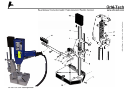
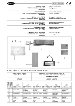
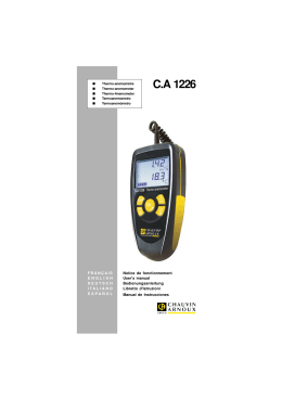
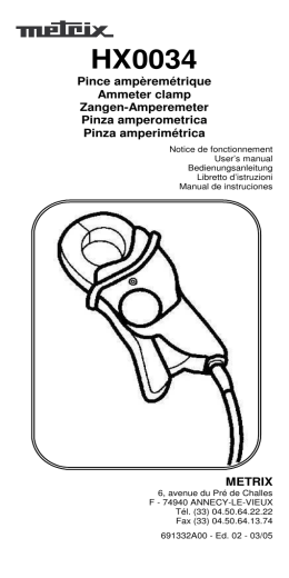
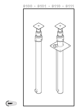
H07024800 / DT2000616-00
Deutsch
English
Italiano
ISTRUZIONI PER L’INSTALLATORE
INSTRUCTIONS FOR THE INSTALLER
AUFBAUANLEITUNG FÜR DEN INSTALLATEUR
INSTRUCTIONS POUR L’INSTALLATEUR
Français
Il libretto istruzioni è parte integrante del prodotto. - The instruction booklet is an integral part of the product. - Die Anleitung ist Bestandtel des Produktes - Le manuel fait partie intégrante du produit.
Raccordo aria comburente Ø 35/60
Combustion air connector Ø 35/60
Frischluftzufuhrs-Anschluss Ø 35/60
Raccordement pour l’air de
combustion Ø 35/60
DIMENSIONI
Italiano
DT2032911-00
!6*
40
17,5
11
32,7
Dimensioni in cm.
* Diametro raccordo presa aria esterna
INSTALLAZIONE
DT2012043-00
Nel caso in cui la stufa sia già installata,
scollegarla dalla canna fumaria e spostarla in
avanti per poter operare.
Togliere il laterale destro (ove presente)
seguendo a ritroso quanto riportato nel libretto
“ISTRUZIONI PER L’INSTALLATORE”.
Fig. 1
Inserire il raccordo Ø 35/60 fino in battuta. (Fig. 1)
Posizionare il laterale destro concludendo
l’installazione del rivestimento come descritto nel
libretto “ISTRUZIONI PER L’INSTALLATORE”.
Collegare la stufa alla canna fumaria (vedi libretto
istruzioni allegato al prodotto).
2
H07024800 / DT2000616-00
DT2032906-0
DIMENSIONS
English
DT2032911-00
!6*
40
17,5
11
32,7
Measurements in cm.
* Diameter for combustion air connection.
INSTALLATION
DT2012043-00
If the stove is already installed, disconnect it from
the flueway and move it forwards to be able to
carry out work.
Remove the right side panel (where fitted) following
the procedure described in the “INSTRUCTIONS
FOR THE INSTALLER” booklet in the reverse
order.
Fig. 1
Insert the connector Ø 35-60 as far as it will go.
(Fig. 1)
Fit the right side panel to finish installation of the
cladding, as described in the “INSTRUCTIONS FOR
THE INSTALLER” booklet.
DT2032906-0
Connect the stove to the flueway (see instruction
booklet accompanying the product).
H07024800 / DT2000616-00
3
ABMESSUNGEN
DT2032911-00
!6*
Deutsch
40
17,5
11
32,7
Maßangaben in cm.
* Durchmesser Anschluss Frischluftzufuhr
INSTALLATION
DT2012043-00
Sollte der Ofen schon aufgestellt sein, entkoppeln
Sie ihn vom Rauchabzug und schieben Sie ihn
nach vorn, um daran arbeiten zu können.
Enfernen Sie die rechte Seitenverkleidung
(falls vorhanden) und gehen Sie in der
umgekehrten
Reihenfolge
als
in
den
„INSTALLATIONSANLEITUNGEN“ beschrieben vor.
Abb. 1
Setzen Sie den Anschluss Ø 35-60 bis zum
Anschlag ein. (Abb. 1)
Bringen Sie die rechte Seitenverkleidung wieder an
und schließen Sie die Anbringung der Verkleidung
wie in den „INSTALLATIONSANLEITUNGEN“
beschrieben ab.
Schließen Sie den Ofen an den Rauchabzug
an (siehe die dem Produkt beiliegende
Betriebsanleitung).
4
H07024800 / DT2000616-00
DT2032906-0
DIMENSIONS
DT2032911-00
!6*
40
17,5
11
Français
32,7
Dimensions en cm.
* Diamétre raccord pour l’air de combustion
INSTALLATION
DT2012043-00
Si le poêle est déjà installé, débranchez-le du
conduit de cheminée et déplacez-le vers l’avant
pour pouvoir travailler.
Enlevez le panneau latéral droit (s’il est présent)
en procédant dans le sens contraire à ce qui est
indiqué dans le livret “INSTRUCTIONS POUR
L’INSTALLATEUR”.
Fig. 1
Emboîtez le raccord Ø 35-60 jusqu’à la butée
(Fig. 1).
Montez le panneau latéral droit et terminez le
montage du revêtement ainsi qu’il est indiqué dans
le livret “INSTRUCTIONS POUR L’INSTALLATEUR”.
DT2032906-0
Raccordez le poêle au conduit de cheminée (voyez
la notice jointe au produit).
H07024800 / DT2000616-00
5
6
H07024800 / DT2000616-00
H07024800 / DT2000616-00
7
Technical Department - Cod. H07024800 / DT2000616 rev. 00 - (07-2010)
Via Montello, 22
31011 Casella d’Asolo (TV) - ITALY
Tel. +39.04235271 - Fax +39.042355178
www.piazzetta.it
e-mail: [email protected]
H07024800 / DT2000616-00
Scarica