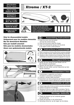
KIT RICAMBIO TRASFORMATORE TOROIDALE
TRANSFORMER SPARE PARTS KIT
I
GB
KIT RECHANGE TRANSFORMATEUR TOROÏDAL
F
ERSATZTEILKIT DES RINGKERNTRANSFORMATORS
D
COMPONENTI - COMPONENTS - COMPOSANTS - EINZELKOMPONENTEN
1
1
2
2
3
3
4
4
5
5
6
6
7
7
8
8
-
N. 1 TOROIDE 40VA 230V.
NO. 1 TOROID 40VA 230V.
N. 1 COPERCHIO TRASFORMATORE.
NO. 1 TRANSFORMER COVER.
N. 1 DIMA DI FORATURA .
NO. 1 DRILL HOLE TEMPLATE.
N. 1 VITE.
NO. 1 SCREW
N. 2 ROSETTE.
NO. 2 WASHERS.
N. 1 ROSETTA DENTELLATA .
NO. 1 GROOVED WASHER.
N. 2 DADI.
NO. 2 NUTS.
N. 1 MORSETTIERA (4 poli).
NO. 1 TERMINAL BLOCK (4 stud).
1
1
2
2
3
3
4
4
5
5
6
6
7
7
8
8
-
N. 1 TOROÏDAL 40VA 230V.
Nr. 1 RINGKERNTRANSFORMATOR 40 VA 230 V.
N.1 COUVERCLE TRANSFORMATEUR.
Nr. 1 ABDECKUNG DES TRANSFORMATORS.
N. 1 GABARIT DE PERÇAGE.
Nr. 1 BOHRSCHABLONE.
N. 1 VIS.
Nr. 1 SCHRAUBE.
N. 2 RONDELLES
Nr. 2 UNTERMUTTERSCHEIBEN.
N. 1 RONDELLE À DENTURE
Nr. 1 GEZAHNTE UNTERMUTTERSCHEIBE.
N. 2 ÉCROUS
Nr. 2 SCHRAUBENMUTTERN.
N. 1 BOÎTE À BORNES (4 pôles)
Nr. 1 ANSCHLUSSKLEMME (4polig).
1
- Disinserire l’apparecchio togliendo la spina
o agendo sull’interruttore generale.
- Smontare la cappa (per le operazioni di
smontaggio fare riferimento al manuale istruzioni di uso e installazione).
- Posizionare la dima di foratura 3 come da
Fig. 1 ed eseguire un foro con una punta da
Ø4 mm.
- Disconnect the cooker-hood by taking the
plug away or by operating on the general
switch.
- Dismount the cooker hood (for dismounting
procedure refer to manual for use and
installation instructions).
- Position the drill hole template 3 as per Fig. 1 and perform a drill hole with a Ø4 mm drill
point.
- Débranchez la hotte enlevant la fiche ou en agissant sur l’interrupteur général.
- Démonter la hotte (pour les opérations de démontage, se référer au manuel d’utilisation
et d’installation).
- Positionner le gabarit de perçage 3 comme à la Fig.1 et pratiquer un trou avec une
pointe de Ø4 mm.
- Die haube vom stromkreis trennen: Entweder den stecker herauszienen oder die
sicherung ausschalten.
- Die Dunstabzugshaube auseinandermontieren (dabei den Anleitungen des Handbuchs
zum Gebrauch und zur Installation folgen).
- Die Bohrschablone 3, wie in Abb. 1 dargestellt, positionieren und mit einer
Bohrerspitzte von Ø 4 mm ein Loch bohren.
2
- Assiemare la vite 4 con le rosette
(dentellata 6, piana 5, piana 5) ed il dado
7 come da Fig. 2 e Fig. 3.
- Assemble the 4 screws with the washers
(grooved 6, flat 5, flat 5) and the nut 7
as per Fig. 2 and Fig. 3.
- Assembler la vis 4 avec les rondelles
(à denture 6, plate 5, plate 5) et l’écrou
7 comme à la Fig. 2 et à la Fig. 3.
- Die Schraube 4 mit den
Untermutterscheiben (gezahnt 6, glatt
5, glatt 5) und der Schraubenmutter
7, so wie in den Abb. 2 und 3
dargestellt, zusammensetzen.
- Smontare il supporto interruttori Fig. 4 seguendo lo Schema Elettrico A, scollegare
i fili dal trasformatore elettronico e collegarli alla morsettiera, quindi collegare i fili
del trasformatore toroidale 1 (Fig.5).
- Dismount the switch housing Fig. 4
following the electrical scheme A,
disconnect the wires from the electronic
transformer and connect to the terminal
block, then connect the toroidal
transformer 1 wires (Fig.5).
- Démonter le support interrupteurs Fig.
4 en suivant le schéma électrique A,
débrancher les fils du transformateur
électronique et les raccorder à la boîte
à bornes, raccorder ensuite les fils du
transformateur toroïdal 1 (Fig.5).
- Die Halterung der Schalter (Abb. 4)
abmontieren, dabei dem elektrischen
Schema A folgen, danach die Kabel
vom elektronischen Transformator
entfernen und mit der
Anschlussklemme verbinden,
schliesslich die Kabel des
Ringkerntransformators 1
anschliessen (Abb. 5).
2
3
4
5
3
- Asportare le parti evidenziate sul supporto interruttori e sul diffusore come in
Fig. 6 e Fig. 7.
- Remove the parts highlighted on the
switch housing and on the diffuser as in
Fig. 6 e Fig. 7.
- Enlever les parties mises en évidence
sur le support interrupteurs et sur le
diffuseur comme à la Fig. 6 e Fig. 7.
- Die gekennzeichneten Teile der
Halterung des Schalters und des
Verteilers, wie in den Abb. 6 und 7,
entfernen.
- Sistemare la morsettiera 8 ed il trasformatore toroidale 1 nelle lori sedi e
riposizionare il supporto interruttori come
in Fig. 8.
- Arrange the terminal block and the
toroidal transformer 1 in their housing
and replace the switch housing as in Fig.
8.
- Mettre la boîte à bornes et le
transformateur toroïdal 1 dans leurs
sièges et repositionner le support
interrupteurs comme à la Fig. 8.
- Die Anschlussklemme und den
Ringkerntransformator 1 an den dafür
vorgesehenen Plätzen installieren,
dann die Halterung des Schalters, so
wie in Abb. 8, wieder einsetzen.
4
6
7
8
- Posizionare il coperchio trasformatore 2
come in Fig. 9; avvitare il dado di fissaggio.
- Riassemblare i componenti rimossi.
- Put the transformer cover as illustrated
in Fig. 9; screw in the fixing nut.
- Re-assemble the removed components.
- Positionnez
le
couvercle
transformateur comme illustré dans
l’image 9 ; visser l’écrou de fixage.
- Rassembler les composants enlevés.
- Den deckel des 2 Transformators
positionieren wie in Abb. 9
positionieren und die
Schraubenmutter festschrauben.
- Die entfernten Einzelteile wieder
zusammenfügen.
9
5
6
7
4329521 01 - 000927
Scarica