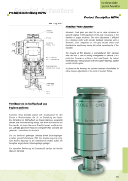
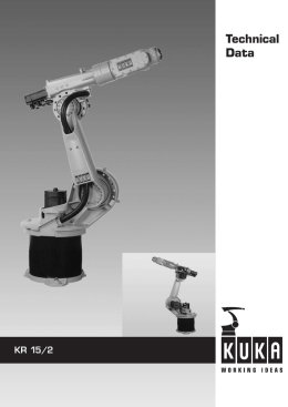
Units
Units
SHG-2-UH Units
Technische Daten
Technical Data
Rating Table
Leistungsdaten
Tabelle / Table 137.1
#
%
2
0
SHG-2UH Unterset-
Grenze für
Grenze für Nenndrehmoment
Baugröße zung 1)
wiederholbares Durchschnitts- bei Nenndrehzahl 2)
Size
Spitzendrehmoment drehmoment
2000 min-1
Maximale
Antriebsdreh-
zahl min-1
Grenze für
mittlere Antriebs-
drehzahl min-1
Massen-
trägheits-
moment 3)
Gewicht
Maximum
Input Speed
rpm
Limit for Average
Input Speed
rpm
Moment
of Interia 3)
Weight
Limit for Repeated
Peak Torque
Limit for
Average
Torque
Rated Torque at
Rated speed 2)
2000 min-1
Limit for
Momentary
Peak Torque
i; R
TR
Nm
TA
Nm
TN
Nm
TM
Nm
Öl 4)
Oil 4)
Fett 3)
Grease 3)
Öl 4)
Oil 4)
Fett 3)
Grease 3)
kgm2
kg
80
100
120
160
2743
2990
3263
3419
1352
1976
2041
2041
969
1236
1236
1236
4836
6175
6175
6175
3500
2800
800
800
94,1x10⁻⁴
28,5
Ratio 1)
65
Grenze für
Kollisions-
drehmoment
1)
Die in der Bestellbezeichnung angeführte Untersetzung ist gültig für einen
Einsatz gemäß Abbildung 1, s. S. 432. Siehe auch „Bemerkung“ im Kapitel
„Bestellbezeichnung“ dieses Produktes.
2)
Für dieses Produkt ist die maximal zulässige Einschaltdauer begrenzt, siehe
auch S. 128.
3)
Bei Fettschmierung mit Harmonic Drive SK- oder 4BNo.2 Fetten.
4)
Ggf. müssen die Gehäuseabmessungen bei Ölschmierung geändert werden.
Bitte Rücksprache mit der Harmonic Drive AG.
The ratio mentioned in the ordering code table is valid only for the configuration according to fig. 1, cf. page 432. Please also consider “Note“ given in the
chapter “Ordering Code“ of this product.
2)
The maximum duty cycle of this product is limited; please refer also to page
128.
3)
For grease lubrication with Harmonic Drive SK- or 4BNo.2 grease.
4)
The housing dimensions may have to be changed for oil lubrication.
Please ask Harmonic Drive AG.
Abmessungen
Dimensions
1)
Abb. / Fig. 137.2
#
%
2
0
137
Units SHG-2UH
Accuracy Data
Genauigkeit
Tabelle / Table 138.1
[arcmin]
SHG Unit Baugröße / Size
Übertragungsgenauigkeit / Transmission Accuracy
Hystereseverlust / Hysteresis Loss
Lost Motion
Wiederholgenauigkeit / Repeatability
65
<1
<1
<1
< ± 0,1
#%20
Torsional Stiffness
Torsionssteifigkeit
Tabelle / Table 138.2
#%20
SHG Unit
Baugröße / Size
65
T1 in Nm
T2 in Nm
K3 in Nm/rad
K2 in Nm/rad
K1 in Nm/rad
235
843
9,8 x 105
8,8 x 105
5,4 x 105
No-Load Starting Torque
Lastfreies Anlaufdrehmoment
Tabelle / Table 138.3
[Ncm]
#%20
SHG Unit
Untersetzung / Ratio
Baugröße / Size
65
80
100
120
160
314
297
287
276
No-Load Back Driving Torque
Lastfreies Rückdrehmoment
Tabelle / Table 138.4
[Nm]
#%20
SHG Unit
Untersetzung / Ratio
Baugröße / Size
65
80
100
120
160
301
356
413
530
Lastfreies Laufdrehmoment s. Seite 125, Wirkungsgrad s. Seite 126, Kontinuierlicher Betrieb s. Seite 128.
138
For No-Load Running Torque cf. page 125, Efficiency data cf. page 126,
Continuous Operation cf. page 128.
Units
Units
SHG-2UH Units
Technische Daten der Eingangslagerung
Performance Data for Input Bearing
Die Hohlwelle der SHG-2UH Unit ist mit zwei einreihigen
Rillenkugellagern gelagert. Abb. 139.2 zeigt die Kraftangriffspunkte der in Abb. 139.3 dargestellten max. zulässigen Radialund Axialkräfte.
The hollow shaft incorporated in the SHG-2UH Unit is supported
by two single-row deep-groove ball bearings. Fig. 139.2 shows the
points of application of force of the maximum permissible radial
and axial loads as indicated in Fig. 139.3.
Beispiel: Wenn die Hohlwelle einer SHG-65-2UH mit einer Axialkraft von 800 N vorgespannt ist, beträgt die max. zulässige
Radialkraft 1300 N.
Example: If the hollow shaft of a SHG-65-2UH Unit is subjected
to an axial load of 800 N, then the maximum permissible radial
force will be 1300 N.
Die in der Abb. 139.3 dargestellten Maximalwerte gelten für eine
durchschnittliche Eingangsdrehzahl von 2000 min-1 und eine
mittlere Lagerlebensdauer von L50=35000 h.
The maximum values as given in Fig. 139.3 are valid for an
average input speed of 2000 rpm and a mean bearing life of
L50=35000 h.
Tabelle / Table 139.1
#
%
2
0
SHG-2UH
Baugröße / Size
65
Lager A Lager B
Abstand
Abstand
Max. zul. Radialkraft
Bearing A
Bearing B
Offset
Offset
Max. permissible radial load
C [N] C0 [N]
C [N]
C0 [N]
a [mm]
b [mm]
Fr [N]
42500
36500
19600
21200
67
44,5
2300
Abb. / Fig. 139.2
#%20
Lager A
Lager B
Bearing A
Bearing B
Abb. / Fig. 139.3
#
%
2
0
Fr
- Fa +
s
139
Units SHG-2UH
Leistungsdaten der Abtriebslagerung
Output Bearing Ratings
Dieses Produkt ist mit einem hoch belastbaren Kreuzrollenlager
am Abtrieb ausgerüstet, das sowohl hohe Axial- und Radialkräfte als auch hohe Kippmomente aufnimmt. Dadurch wird das
Getriebe von äußeren Belastungen freigehalten, so dass eine
lange Lebensdauer und gleichbleibende Genauigkeit gewährleistet sind. Für den Anwender bedeutet die Integration dieses
Abtriebslagers eine bemerkenswerte Reduzierung der Konstruktions-, Fertigungs- und Montagekosten, da zusätzliche externe
Lager nicht erforderlich sind. Falls trotz des leistungsfähigen
Abtriebslagers in der Konstruktion eine zusätzliche Lagerung des
anzutreibenden Maschinenelementes eingesetzt werden soll, ist
unbedingt darauf zu achten, dass keine Verspannungen zwischen
dem spielfreien Abtriebslager des Getriebes und der Zusatzlagerung auftreten können. Das Getriebelager sollte möglichst als
Festlager eingesetzt werden. Die Leistungsdaten des Abtriebslagers sind in Tabelle 140.1 angegeben.
This product incorporates a high stiffness cross-roller bearing
to support output loads. This specially developed bearing can
withstand high axial and radial forces as well as high tilting
moments. The reduction gear is thus protected from external
loads, so guaranteeing a long life and constant performance.
The integration of an output bearing also serves to reduce subsequent design and production costs, by removing the need for
additional output bearings in many applications. However, in
some applications the machine element to be driven requires
additional bearing support. In this case, please take care to avoid
overdetermination of the bearing arrangement. The cross-roller
bearing of the Unit should be used as the fixed bearing, whilst
the additional support bearing should be floating, if possible.
Table 140.1 lists ratings and important dimensions for the output bearings.
Tabelle / Table 140.1
#
%
2
0
SHG
Teilkreis ø 4)
Units
Baugröße
SHG
Units
Size
65
Abstand
Dynamische
Tragzahl
Statische
Tragzahl
Zulässiges dynamisches Kippmoment1)
Zulässiges
statisches
Kippmoment 2)
Kippsteifigkeit
Zulässige
Axiallast Fa 3)
Zulässige
Radiallast Fr 3)
Pitch Circle
ø 4)
Offset
rating
Dynamic
load rating
Static load
rating
Permissible dynamic Tilting
Moment 1)
Permissible
static Tilting
Moment 2)
Moment
Stiffness
Permissible
Axial Load3)
Permissible
Radial Load 3)
dp [m]
R [m]
C [N]
C0 [N]
M [Nm]
M0 [Nm]
KB [Nm/arcmin]
Fa [N]
Fr [N]
0,218
0,072
130000
223000
2740
16200
2158
60000
40000
Die Lebensdauer des Getriebes wird i. d. R. von der Lebensdauer des Wave Generator Kugellagers bestimmt. Je nach Belastung kann jedoch auch das Abtriebslager für die Lebensdauer bestimmend sein.
Normally, the gear life is determined by the life of the Wave Generator bearing.
Depending on the specific load conditions the output bearing can also be determinant for the gear life.
Diese Daten gelten für drehende Getriebe. Sie basieren nicht auf der Lebensdauergleichung des Abtriebslagers, sondern auf der max. zulässigen Verkippung des Harmonic Drive Einbausatzes. Die angegebenen Daten dürfen auch
dann nicht überschritten werden, wenn die Lebensdauergleichung des Lagers
höhere Werte zulässt.
2)
Diese Daten gelten für stehende Getriebe und einen statischen Sicherheitsfaktor fs = 1,5. Für andere fs siehe Kapitel „Projektierung mit Harmonic Drive
Getrieben“.
3)
Die Daten gelten für: fw = 1,3; n = 15 min-1 und L10 = 15000h.
4)
Je nach Lagerlieferant können die Teilkreisdurchmesser geringfügig von den
Katalogdaten abweichen.
1)2)3)
Die Daten gelten unter folgender Voraussetzung:
Für: M, M0 : Fa = 0, Fr = 0 | Fa : M = 0, Fr = 0 | Fr : M = 0, Fa= 0
1)
1)
140
These values are valid for moving gears. They are not based on the equation for
lifetime calculation of the output bearing but on the maximum allowable deflection of the Harmonic Drive component set. The values indicated in the
table must not be exceeded even if the lifetime equation of the bearing permits
higher values.
2)
These values are valid for gears at a standstill and for a static load safety factor
fs = 1.5. For other values of fs , please refer to section „Engineering Data for
Harmonic Drive Gears“.
3)
These data are valid for: fW = 1,3; n = 15 rpm and L10 = 15000h
4)
Depending on the bearing manufacturer the pitch circle diameter may differ
slightly from the data given in the catalogue.
1)2)3)
These data are only valid if the following conditions are fulfilled:
For: M, M0 : Fa = 0, Fr = 0 | Fa : M = 0; Fr = 0 | Fr : M = 0, Fa = 0
Units
Units
SHG-2UH Units
Toleranzen des Abtriebsflansches
Output Flange Tolerances
Bei dieser Unit wird die Last über einen Flansch mit dem Kreuzrollenabtriebslager verbunden.
Je nach Befestigungsart kann der mit dem Außenring oder der
mit dem Innenring des Abtriebslagers verbundene Flansch als
Abtrieb benutzt werden, s. Abb. 141.1 und Abb. 141.2. Die in
Tabelle 141.3 angeführten Toleranzen beinhalten die Summe aus
Lager- und Flanschtoleranzen.
In the case of the SHG-2UH Unit the load is connected to the
output bearing by means of a flange. Depending on the manner
of fastening, either the flange which is connected to the outer
ring, or the flange which is connected to the internal ring of the
output bearing, can be used as output element (cf. Fig. 141.1 and
Fig. 141.2). The tolerance values indicated in Table 141.3 are the
sum of bearing and flange tolerances.
Abb. / Fig. 141.1
Abb. / Fig. 141.2
#%20
#
%
2
0
Tabelle / Table 141.3
[mm]
#
%
2
0
Baugröße / Size
A
B
C
D
E
F
G
H
I
K
65
0,070
0,070
0,130
0,092
0,080
0,075
0,075
0,055
0,130
0,092
Assembly
Montage
Abb. / Fig. 141.4
#%20
141
Units SHG-2UH
Montage des Abtriebsflansches
Assembly of the Output Flange
Tabelle / Table 142.1
Montage des Gehäuseflansches
Assembly of the Housing Flange
Tabelle / Table 142.2
%
#
0
2
%
#
0
2
Baugröße / Size
65
Baugröße / Size
65
Anzahl der Schrauben
Number of screws
16
Anzahl der Schrauben
Number of screws
16
Schraubengröße
Size of screws
M10
Schraubengröße
Size of screws
M10
Teilkreisdurchmesser
Pitch circle diameter
[mm]
195
Teilkreisdurchmesser
Pitch circle diameter
[mm]
258
Anzugsmoment/Schraube Screw tightening torque
[Nm]
89
Anzugsmoment/Schraube Screw tightening torque
[Nm]
74
Übertragbares Drehmoment1) Torque transmitting capacity1)
[Nm]
8658
Übertragbares Drehmoment1) Torque transmitting capacity1)
[Nm]
9546
Die Daten der Tabellen 142.1 und 142.2 sind gültig
für vollständig entfettete Anschlussflächen (Reibungskoeffizient µ = 0,15) und Schraubenqualität 12.9. The values given in Tables 142.1 and 142.2 are valid
for completely degreased mating surfaces (friction
coefficient µ = 0.15) and for 12.9 quality screws.
1)
1)
Verschraubungen
Screw Connections
Die SHG-2UH Unit ist im Auslieferungszustand nur mit wenigen
Schrauben fixiert. Die volle Abtriebslager- und Drehmomentbelastung darf daher erst dann erfolgen, wenn die Unit vollständig
mit dem Maschinengehäuse und der Last verschraubt ist.
On delivery, the SHG-2UH Unit is pre-assembled only by means
of a few screws. Therefore the full output bearing and torque load
can only be applied after the unit has been mounted completely
to the machine frame and the load.
Schmierung
Lubrication
Die Units werden einbaufertig geliefert. Sie sind werksseitig mit
einer Lebensdauer-Fettschmierung versehen. Das eingesetzte
Harmonic Drive Hochleistungsfett ist auf die speziellen Anforderungen der Harmonic Drive Getriebe abgestimmt. Es gewährleistet konstante Genauigkeit der Getriebe über die gesamte Lebensdauer. Nachschmieren der Units ist nicht erforderlich.
Harmonic Drive SHG Series Units are delivered ready for use. They
are supplied with lifetime lubricant which is a high performance
grease that meets the specific requirements of the Harmonic Drive
gears. It guarantees constant accuracy of the gears for the whole
life. A re-lubrication of the Units is not necessary.
Hinweis:
Weitere Informationen bezüglich der Themen „Schmierstoffe und Schmierung bei
erweiterten Betriebstemperaturen/Sonderschmierstoffe“ finden Sie im Kapitel
„Erläuterungen zu Schmierstoffen“ auf Seite 439 und 440.
Note:
For further information regarding the subjects “lubricants and lubrication at extended operating temperatures/special lubricants“ please refer to chapter “Lubricant
Explanations“ on pages 439 and 440.
142
Scarica