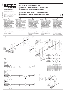
ISTRUZIONI PER L’INSTALLAZIONE, L’USO E LA MANUTENZIONE - IT
INSTRUCTIONS FOR INSTALLATION, USE AND MAINTENANCE - EN
ANWEISUNGEN FÜR DIE AUFSTELLUNG, DEN GEBRAUCH UND DIE WARTUNG - DE
INSTRUCTIONS POUR L’INSTALLATION, L’UTILISATION ET L’ENTRETIEN – FR
TermoRossella Plus DSA – TermoNicoletta DSA
TermoRossella Plus forno DSA – TermoNicoletta forno DSA
Testata secondo / Tested according to / Geprüft nach / Certifié selon / : EN13240
|
IT – PER EVITARE DANNI ALL’APPARECCHIO, RISPETTARE IL CARICO ORARIO DI COMBUSTIBILE INDICATO
NEL PRESENTE LIBRETTO.
EN – TO AVOID DAMAGES TO THE APPLIANCE, PLEASE RESPECT THE MAX. FUEL QUANTITY (KG/HR)
INDICATED IN THE USER’S MANUAL.
DE – UM SCHÄDEN AN DEM GERÄT ZU VERMEIDEN, BITTE BEACHTEN SIE DIE BRENNSTOFFMENGE (KG/H)
LT. BEDIENUNGSANLEITUNG.
FR – POUR EVITER DES DOMMAGES A L’APPAREIL RESPECTER LA QUANTITE’ MAX. DE COMBUSTIBLE (KG/H)
COMME INDIQUE DANS LA NOTICE D’UTILISATION.
NORME DI SICUREZZA SUGLI APPARECCHI
Per il rispetto delle norme di sicurezza è obbligatorio installare
e utilizzare i nostri prodotti seguendo scrupolosamente le indicazioni fornite nel presente manuale.
SAFETY REGULATIONS ON THE APPLIANCES
To meet safety regulations, it is compulsory to install and use our products
carefully following the instructions contained in this manual.
SICHERHEITSVORSCHRIFTEN BEI DEN AUSRÜSTUNGEN
Um die Sicherheitsvorschriften zu beachten, ist es notwendig, unsere Produkte
vorsichtig nach den in diesem Handbuch enthaltenen Anweisungen zu installieren und anzuwenden.
RÉGLÉS DE SÉCURITÉ SUR LES APPAREILS
Selon les normes de sécurité sur les appareils l’acheteur
et le commerçant sont contraints de s’informer sur le fonctionnement correct sur la base des instructions d’emploi.
TERMOROSSELLA PLUS DSA / FORNO DSA – TERMONICOLETTA DSA / FORNO DSA
DICHIARAZIONE DI CONFORMITA’ DEL COSTRUTTORE
Oggetto: Assenza di amianto e cadmio
Si dichiara che tutti i nostri apparecchi vengono assemblati con materiali che non presentano parti di amianto o suoi derivati e che nel
materiale d’apporto utilizzato per le saldature non è presente/utilizzato in nessuna forma il cadmio, come previsto dalla norma di riferimento.
Oggetto: Regolamento CE n. 1935/2004
Si dichiara che in tutti gli apparecchi da noi prodotti, i materiali destinati a venire a contatto con i cibi sono adatti all’uso alimentari, in
conformità al Regolamento CE in oggetto.
DECLARATION OF CONFORMITY OF THE MANUFACTURER
Object: Absence of asbestos and cadmium
We declare that the materials used for the assembly of all our appliances are without asbestos parts or asbestos derivates and that in the
material used for welding, cadmium is not present, as prescribed in relevant norm.
Object: CE n. 1935/2004 regulation.
We declare that in all products we produce, the materials which will get in touch with food are suitable for alimentary use, according to the
a.m. CE regulation.
KONFORMITÄTSERKLÄRUNG DES HERSTELLERS
Betreff: Fehlen von Asbest und Kadmium
Wir bestätigen, dass die verwendeten Materialen oder Teilen für die Herstellung der La Nordica Geräte ohne Asbest und Derivat sind und
auch das Lot für das Schweißen immer ohne Kadmium ist.
Betreff: Ordnung CE n. 1935/2004.
Wir erklären in alleiniger Verantwortung, dass die Materialen der Teile, die für den Kontakt mit Lebensmitteln vorgesehen sind, für die
Nahrungsbenutzung geeignet sind und der Richtlinien CE n. 1935/2004 erfüllen.
DÉCLARATION DE CONFORMITÉ DU CONSTRUCTEUR
Objet: Absence d’amiante et de cadmium
Nous déclarons que tous nos appareils sont assemblés avec des matériaux ne comportant pas de parties en amiante ou ses dérivés et
que dans le matériau d’apport utilisé pour les soudures le cadmium n’est pas présent ni utilisé sous aucune forme que ce soit, comme il
est prévu par la norme de référence.
Objet: Règlement CE n. 1935/2004
Nous déclarons que tous nos produits, les matériaux destinés à entrer en contact avec les aliments sont indiqués pour l’usage des
aliments, conformément au Règlement CE cité à l’objet.
7197100 - IT - EN - DE - FR 3
TERMOROSSELLA PLUS DSA / FORNO DSA – TERMONICOLETTA DSA / FORNO DSA
1.
2.
3.
4.
5.
6.
7.
8.
9.
10.
11.
12.
13.
14.
1.
2.
3.
4.
5.
6.
7.
8.
9.
10.
11.
12.
13.
14.
4
IT - INDICE
AVVERTENZE GENERALI .......................................................................................................................................................................................6
NORME PER L’INSTALLAZIONE.............................................................................................................................................................................6
2.1. Vaso di espansione APERTO..........................................................................................................................................................................6
2.2. Vaso di espansione CHIUSO...........................................................................................................................................................................7
2.3. VALVOLA MISCELATRICE TERMOSTATICA AUTOMATICA (OPTIONAL)....................................................................................................7
2.4. VALVOLA SCARICO TERMICO (OPTIONAL).................................................................................................................................................7
2.5. COLLEGAMENTO E CARICO DELL’IMPIANTO.............................................................................................................................................8
SICUREZZA ANTINCENDIO.....................................................................................................................................................................................8
3.1. PRONTO INTERVENTO..................................................................................................................................................................................8
DESCRIZIONE TECNICA..........................................................................................................................................................................................9
CANNA FUMARIA.....................................................................................................................................................................................................9
5.1. COMIGNOLO...................................................................................................................................................................................................9
5.2. COLLEGAMENTO AL CAMINO.....................................................................................................................................................................10
5.3. COLLEGAMENTO ALLA CANNA FUMARIA DI UN CAMINETTO O FOCOLARE APERTO........................................................................10
AFFLUSSO D’ARIA NEL LUOGO D’INSTALLAZIONE DURANTE LA COMBUSTIONE.....................................................................................10
COMBUSTIBILI AMMESSI / NON AMMESSI......................................................................................................................................................... 11
ACCENSIONE.......................................................................................................................................................................................................... 11
8.1. FUNZIONAMENTO NORMALE.....................................................................................................................................................................12
8.2. MANCANZA DI ENERGIA ELETTRICA.........................................................................................................................................................13
8.3. FUNZIONAMENTO NEI PERIODI DI TRANSIZIONE...................................................................................................................................13
8.4. UTILIZZO COME NORMALE STUFA............................................................................................................................................................13
FERMO ESTIVO.......................................................................................................................................................................................................13
MANUTENZIONE E CURA......................................................................................................................................................................................14
10.1. PULIZIA CANNA FUMARIA...........................................................................................................................................................................14
10.2. PULIZIA VETRO............................................................................................................................................................................................14
10.3. PULIZIA CASSETTO CENERE.....................................................................................................................................................................14
10.4. MANUTENZIONE DELL’IMPIANTO IDRAULICO..........................................................................................................................................14
DATI TECNICI..........................................................................................................................................................................................................15
SCHEMA DI INSTALLAZIONE / INSTALLATION LAY-OUT / ALLGEMEINES INSTALLATIONSSCHEMA THERMOKÜCHE / INSTALLATION
SCHEME..................................................................................................................................................................................................................45
CERAMICHE / CERAMICS / KACHELN / FAIENCES / MONTAGE DES FAIENCES (TERMONICOLETTA).......................................................50
SCHEDE TECNICHE / TECHNICAL DATA SHEETS / TECHNISCHE PROTOKOLLE / FICHES TECHNIQUES.................................................51
EN - CONTENTS
GENERAL PRECAUTIONS.....................................................................................................................................................................................16
INSTALLATION REGULATIONS.............................................................................................................................................................................16
2.1. OPEN expansion Tank system.......................................................................................................................................................................16
2.2. CLOSED expansion Tank system..................................................................................................................................................................17
2.3. AUTOMATIC THERMOSTATIC MIXER VALVE - (OPTIONAL).....................................................................................................................17
2.4. HEAT DISCHARGE VALVE - (OPTIONAL) ..................................................................................................................................................17
2.5. SYSTEM CONNECTION AND FILLING........................................................................................................................................................17
FIRE-FIGHTING SAFETY MEASURES...................................................................................................................................................................18
3.1. FIRST-AID MEASURES.................................................................................................................................................................................18
DESCRIPTION.........................................................................................................................................................................................................18
FLUE........................................................................................................................................................................................................................19
5.1. CHIMNEY POT..............................................................................................................................................................................................19
5.2. CONNECTION TO THE CHIMNEY...............................................................................................................................................................19
5.3. CONNECTING A FIREPLACE OR OPEN HEARTH TO THE FLUE.............................................................................................................19
AIR FLOW IN THE PLACE OF INSTALLATION DURING COMBUSTION ...........................................................................................................20
PERMITTED/FORBIDDEN FUELS..........................................................................................................................................................................20
LIGHTING.................................................................................................................................................................................................................21
8.1. NORMAL OPERATION..................................................................................................................................................................................21
8.2. ELECTRICAL POWER SUPPLY FAILURE....................................................................................................................................................22
8.3. OPERATION DURING TRANSITION PERIODS...........................................................................................................................................22
8.4. USE AS A NORMAL STOVE..........................................................................................................................................................................22
SUMMER TIME........................................................................................................................................................................................................22
MAINTENANCE AND CARE...................................................................................................................................................................................23
10.1. CLEANING THE FLUE..................................................................................................................................................................................23
10.2. GLASS CLEANING........................................................................................................................................................................................23
10.3. CLEANING OUT THE ASHES.......................................................................................................................................................................23
10.4. MAINTENANCE ON THE WATER SYSTEM.................................................................................................................................................23
TECHNICAL DATA...................................................................................................................................................................................................24
SCHEMA DI INSTALLAZIONE / INSTALLATION LAY-OUT / ALLGEMEINES INSTALLATIONSSCHEMA THERMOKÜCHE / INSTALLATION
SCHEME..................................................................................................................................................................................................................45
CERAMICHE / CERAMICS / KACHELN / FAIENCES / MONTAGE DES FAIENCES (TERMONICOLETTA).......................................................50
SCHEDE TECNICHE / TECHNICAL DATA SHEETS / TECHNISCHE PROTOKOLLE / FICHES TECHNIQUES.................................................51
7197100 - IT - EN - DE - FR
TERMOROSSELLA PLUS DSA / FORNO DSA – TERMONICOLETTA DSA / FORNO DSA
1.
2.
3.
4.
5.
6.
7.
8.
9.
10.
11.
12.
13.
14.
1.
2.
3.
4.
5.
6.
7.
8.
9.
10.
11.
12.
13.
14.
DE - INHALTSVERZEICHNIS
ALLGEMEINE HINWEISE ......................................................................................................................................................................................25
INSTALLATIONSVORSCHRIFTEN ........................................................................................................................................................................25
2.1. OFFENEM Ausdehnungsgefäß.....................................................................................................................................................................25
2.2. GESCHLOSSENEM Ausdehnungsgefäß .....................................................................................................................................................26
2.3. AUTOMATISCHES THERMOSTAT- MISCHVENTIL (OPTIONAL) ..............................................................................................................26
2.4. WÄRMEABLASSVENTIL (OPTIONAL) ........................................................................................................................................................26
2.5. VERBINDUNG UND LADEN DER ANLAGE.................................................................................................................................................27
BRANDSCHUTZ......................................................................................................................................................................................................27
3.1. NOTHILFEINTERVENTION...........................................................................................................................................................................27
BESCHREIBUNG.....................................................................................................................................................................................................28
RAUCHABZUG........................................................................................................................................................................................................28
5.1. SCHORNSTEINPOSITION............................................................................................................................................................................28
5.2. ANSCHLUSS AN DEN SCHORNSTEIN........................................................................................................................................................29
5.3. ANSCHLUSS AN DEN RAUCHABZUG EINES OFFENEN KAMINS............................................................................................................29
LUFTZUSTROM AM INSTALLATIONSORT WÄHREND DER VERBRENNUNG..................................................................................................29
ZULÄSSIGE / UNZULÄSSIGE BRENNSTOFFE....................................................................................................................................................30
ANFEUERUNG........................................................................................................................................................................................................30
8.1. NORMALER BETRIEB..................................................................................................................................................................................31
8.2. STROMAUSFALL .........................................................................................................................................................................................32
8.3. BETRIEB IN DEN ÜBERGANGSPERIODEN................................................................................................................................................32
8.4. VERWENDUNG ALS NORMALER OFEN.....................................................................................................................................................32
SOMMERLICHE STILLEGUNG...............................................................................................................................................................................32
WARTUNG UND PFLEGE.......................................................................................................................................................................................32
10.1. REINIGUNG DES SCHORNSTEINROHRES................................................................................................................................................32
10.2. REINIGUNG DES GLASES...........................................................................................................................................................................33
10.3. REINIGUNG DES ASCHENKASTENS..........................................................................................................................................................33
10.4. WARTUNG DER HYDRAULIKANLAGE........................................................................................................................................................33
TECHNISCHE DATEN.............................................................................................................................................................................................34
SCHEMA DI INSTALLAZIONE / INSTALLATION LAY-OUT / ALLGEMEINES INSTALLATIONSSCHEMA THERMOKÜCHE / INSTALLATION
SCHEME..................................................................................................................................................................................................................45
CERAMICHE / CERAMICS / KACHELN / FAIENCES / MONTAGE DES FAIENCES (TERMONICOLETTA).......................................................50
SCHEDE TECNICHE / TECHNICAL DATA SHEETS / TECHNISCHE PROTOKOLLE / FICHES TECHNIQUES.................................................51
FR - TABLE DES MATIÈRES
AVERTISSEMENTS GENERAUX............................................................................................................................................................................35
REGLES POUR LA MISE EN PLACE.....................................................................................................................................................................35
2.1. Vase d’expansion OUVERT..........................................................................................................................................................................35
2.2. Vase d’expansion FERME.............................................................................................................................................................................36
2.3. VANNE MELANGEUSE THERMOSTATIQUE AUTOMATIQUE (OPTION) ..................................................................................................36
2.4. VANNE D’ÉVACUATION THERMIQUE (OPTION) .......................................................................................................................................37
2.5. RACCORDEMENT ET CHARGEMENT DE L’INSTALLATION . ...................................................................................................................37
SÉCURITÉ CONTRE LES INCENDIES...................................................................................................................................................................37
3.1. INTERVENTION RAPIDE..............................................................................................................................................................................37
DESCRIPTION ........................................................................................................................................................................................................38
CONDUIT DE LA CHEMINÉE..................................................................................................................................................................................38
5.1. POSITION DU POT DE LA CHEMINÉE........................................................................................................................................................38
5.2. CONNEXION AVEC LA CHEMINÉE..............................................................................................................................................................39
5.3. CONNEXION AU CONDUIT DE FUMÉE D’UNE CHEMINÉE OU D’UN FOYER OUVERT.........................................................................39
AMENÉE D’AIR DANS LE LIEU DE LA MISE EN PLACE DURANT LA COMBUSTION.....................................................................................39
COMBUSTIBLES ADMIS / NON ADMIS.................................................................................................................................................................39
ALLUMAGE.............................................................................................................................................................................................................40
8.1. FONCTIONNEMENT NORMAL.....................................................................................................................................................................41
8.2. ABSENCE D’ENERGIE ELECTRIQUE.........................................................................................................................................................41
8.3. FONCTIONNEMENT PENDANT LES PÉRIODES DE TRANSITION ..........................................................................................................42
8.4. UTILISATION COMME UN POELE NORMAL...............................................................................................................................................42
ARRÊT PENDANT L’ÉTÉ........................................................................................................................................................................................42
ENTRETIEN ET SOIN..............................................................................................................................................................................................43
10.1. NETTOYAGE DU TUYAU D’ÉVACUATION DE LA FUMÉE..........................................................................................................................43
10.2. NETTOYAGE DE LA VITRE..........................................................................................................................................................................43
10.3. NETTOYAGE TIROIR DES CENDRES.........................................................................................................................................................43
10.4. ENTRETIEN DE L’INSTALLATION HYDRAULIQUE.....................................................................................................................................43
DONNÉES TECHNIQUES.......................................................................................................................................................................................44
SCHEMA DI INSTALLAZIONE / INSTALLATION LAY-OUT / ALLGEMEINES INSTALLATIONSSCHEMA THERMOKÜCHE / INSTALLATION
SCHEME..................................................................................................................................................................................................................45
CERAMICHE / CERAMICS / KACHELN / FAIENCES / MONTAGE DES FAIENCES (TERMONICOLETTA).......................................................50
SCHEDE TECNICHE / TECHNICAL DATA SHEETS / TECHNISCHE PROTOKOLLE / FICHES TECHNIQUES.................................................51
7197100 - IT - EN - DE - FR 5
TERMOROSSELLA PLUS DSA / FORNO DSA – TERMONICOLETTA DSA / FORNO DSA
1. AVVERTENZE GENERALI
La responsabilità de La NORDICA S.p.A. è limitata alla fornitura dell’apparecchio.
Il suo impianto va realizzato in modo conforme alla regola dell’arte, secondo le prescrizioni delle presenti istruzioni e le regole della
professione, da personale qualificato, che agisce a nome di imprese adatte ad assumere l’intera responsabilità dell’insieme dell’impianto.
La NORDICA S.p.A. non è responsabile del prodotto modificato senza autorizzazione e tanto meno per l’uso di ricambi non
originali.
2. NORME PER L’INSTALLAZIONE
L’installazione del termoprodotto e degli equipaggiamenti ausiliari, relativi all’impianto di riscaldamento, deve essere conforme a tutte le
Norme e Regolamentazioni attuali ed a quanto previsto dalla Legge.
L’installazione, i relativi collegamenti dell’impianto, la messa in servizio e la verifica del corretto funzionamento devono essere eseguiti
a regola d’arte da personale professionalmente preparato nel pieno rispetto delle norme vigenti, sia nazionali, regionali, provinciali e
comunali presenti nel paese in cui è stato installato l’apparecchio, nonché delle presenti istruzioni.
L’installazione deve essere eseguita da personale autorizzato, che dovrà rilasciare all’acquirente una dichiarazione di conformità
dell’impianto, il quale si assumerà l’intera responsabilità dell’installazione definitiva e del conseguente buon funzionamento del prodotto
installato.
NON SI POSSONO EFFETTUARE MODIFICHE ALL’APPARECCHIO. Non vi sarà responsabilità da parte di La NORDICA S.p.A. in
caso di mancato rispetto di tali precauzioni.
Prima dell’installazione, si consiglia di effettuare un lavaggio accurato di tutte le tubazioni dell’impianto onde rimuovere eventuali residui
che potrebbero compromettere il buon funzionamento del termoprodotto.
IMPORTANTE:
a) In caso di fuoriuscite d’acqua chiudere l’alimentazione idrica ed avvisare con sollecitudine il servizio tecnico di assistenza;
b) La pressione di esercizio dell’impianto deve essere periodicamente controllata.
c) In caso di non utilizzo della caldaia per un lungo periodo è consigliabile l’intervento del servizio tecnico di assistenza per effettuare
almeno le seguenti operazioni:
• chiudere i rubinetti dell’acqua sia dell’impianto termico sia del sanitario;
• svuotare l’impianto termico e sanitario se c’è rischio di gelo.
La NORDICA S.p.A. declina ogni responsabilità per danni a cose e/o persone provocati dall’impianto. Inoltre non è responsabile
del prodotto modificato senza autorizzazione e tanto meno per l’uso di ricambi non originali.
Il Vostro abituale spazzacamino di zona deve essere informato sull’installazione del termoprodotto, affinché possa verificarne il regolare
collegamento alla canna fumaria ed il grado di efficienza di quest’ultima.
Prima dell’installazione eseguire le seguenti verifiche:
• accertarsi che il pavimento possa sostenere il peso dell’apparecchio e provvedere ad un adeguato isolamento nel caso sia costruito
in materiale infiammabile.
• assicurarsi che nella stanza dove sarà installato vi sia una ventilazione adeguata (presenza di presa d’aria (vedi capitolo 6)
• evitare l’installazione in locali con presenza di condotti di ventilazione collettivo, cappe con o senza estrattore, apparecchi a gas
di tipo B, pompe di calore o la presenza di apparecchi il cui funzionamento contemporaneo possa mettere in depressione il locale
(rif. Norma UNI 10683/98)
• accertarsi che la canna fumaria e i tubi a cui verrà collegato l’apparecchio siano idonei al funzionamento dello stesso.
• l diametro dell’apertura per il collegamento al camino deve corrispondere per lo meno al diametro del tubo fumo. L’apertura
dovrebbe essere dotata di una connessione a muro per l’inserimento del tubo di scarico e di un rosone.
I termoprodotti modello DSA possono essere installati sia in un impianto a VASO di espansione APERTO (cap.2.1) sia in un impianto a
VASO di espansione CHIUSO (cap.2.2).
2.1. Vaso di espansione APERTO
L’impianto con vaso di espansione aperto, deve essere OBBLIGATORIAMENTE provvisto di:
1. VASO DI ESPANSIONE APERTO: vaso avente una capacità pari al 10 % del contenuto d’acqua totale del termoprodotto e dell’impianto.
Il vaso va posizionato nel punto più alto dell’impianto almeno 2 m sopra il radiatore posto al livello più alto.
2. TUBO DI SICUREZZA : tubo che collega per la via più breve, senza tratti discendenti o sifonanti la mandata del termoprodotto con la
parte superiore del vaso di espansione aperto. Il tubo di sicurezza deve avere la sezione minima interna di 1’’gas.
3. TUBO DI CARICO : tubo che collega il fondo del vaso di espansione aperto con il tubo di ritorno dell’impianto. La sezione minima
deve essere di ¾”gas. Tutti questi elementi non devono per nessuna ragione avere organi di intercettazione interposti che possano
accidentalmente escluderli e devono essere posizionati in ambienti non esposti al gelo poiché, se dovessero gelare, si potrebbe
verificare la rottura o addirittura l’esplosione del corpo caldaia. In caso di esposizione al gelo sarà opportuno aggiungere all’acqua
dell’impianto una adeguata percentuale di liquido antigelo che consentirà di eliminare completamente il problema. In nessun modo ci
dovrà essere circolazione d’acqua nel vaso di espansione aperto fra il tubo di sicurezza ed il tubo di carico. Questa provocherebbe
l’ossigenazione dell’acqua e la conseguente corrosione del termoprodotto e dell’impianto in tempi molto brevi
4. VALVOLA DI SCARICO TERMICO: costituisce una ulteriore sicurezza positiva in grado di prevenire l’ebollizione anche in assenza
di energia elettrica. E’ costituita da un corpo valvola simile ad una valvola di sicurezza a pressione che, a differenza di questa, si apre
al raggiungimento di una temperatura pretarata ( di solito 94 – 95° C ) scaricando dalla mandata dell’impianto acqua calda che verrà
sostituita con altrettanta acqua fredda proveniente attraverso il tubo di carico del vaso di espansione aperto smaltendo in questo modo
il calore eccessivo
5. VALVOLA DI SICUREZZA da 1,5 bar: la massima pressione di esercizio ammessa per l’impianto è di 1,5 bar (pari a 15 m di colonna
6
7197100 - IT - EN - DE - FR
TERMOROSSELLA PLUS DSA / FORNO DSA – TERMONICOLETTA DSA / FORNO DSA
d’acqua), pressioni superiori possono provocare deformazioni e rotture al corpo caldaia.
6. ALTRI DISPOSITIVI di sicurezza previsti dalla Normativa vigente in materia.
7. POMPA DI CIRCOLAZIONE : deve essere preferibilmente montata sul ritorno per evitare che possa disinnescarsi a temperature
dell’acqua molto elevate, accertarsi però che non faccia circolare l’acqua nel vaso di espansione aperto altrimenti provocherebbe una
continua ossigenazione dell’acqua con conseguente, rapida, corrosione del corpo caldaia. La sua prevalenza deve essere tale da non
provocare una circolazione forzata nel vaso di espansione aperto. Deve inoltre essere collegata ad un termostato o alla centralina
elettronica fornita come OPTIONAL.
8. VALVOLA MISCELATRICE TERMOSTATICA AUTOMATICA – (vedi capitolo 2.3)
IMPORTANTE: i sensori di sicurezza della temperatura devono essere a bordo macchina o a una distanza non maggiore di 30 cm dal
collegamento di mandata del termoprodotto. Qualora i termoprodotti non siano provvisti di tutti i dispostivi, quelli mancanti possono
essere installati sulla tubazione di mandata del termoprodotto entro una distanza dal termoprodotto non maggiore di 1 m.
ATTENZIONE: Per nessuna ragione si deve accendere il fuoco se prima l’impianto non sia stato completamente riempito d’acqua;
il farlo comporterebbe un danneggiamento gravissimo di tutta la struttura. Il riempimento dell’impianto deve essere fatto tramite
il tubo di carico direttamente nella vaschetta del vaso di espansione aperto in modo da evitare che una eccessiva pressione della rete
idrica deformi il corpo caldaia.
L’impianto va tenuto costantemente pieno d’acqua anche nei periodi in cui non è richiesto l’uso. Durante il periodo invernale un’eventuale
non attività va affrontata con l’aggiunta di sostanze antigelo.
2.2. Vaso di espansione CHIUSO
L’impianto con vaso di espansione CHIUSO, deve essere OBBLIGATORIAMENTE provvisto di:
1. VALVOLA DI SICUREZZA da 3 bar: la massima pressione di esercizio ammessa per l’impianto è di 3 bar (pari a 30 m di colonna
d’acqua), pressioni superiori possono provocare deformazioni e rotture del corpo caldaia.
2. VALVOLA MISCELATRICE TERMOSTATICA AUTOMATICA – (vedi capitolo 2.3)
3. VALVOLA DI SCARICO TERMICO o SCARICO DI SICUREZZA TERMICA (a sicurezza positiva, cioè in caso di guasto della valvola
questa continua a scaricare lo stesso)
4. VASO DI ESPANSIONE CHIUSO
5. TERMOSTATO DI COMANDO DEL CIRCOLATORE
6. TERMOSTATO DI ATTIVAZIONE DELL’ALLARME ACUSTICO
7. ALLARME ACUSTICO
8. INDICATORE DI TEMPERATURA
9. INDICATORE DI PRESSIONE
10. SISTEMA DI CIRCOLAZIONE
IMPORTANTE: i sensori di sicurezza della temperatura devono essere a bordo macchina o a una distanza non maggiore di 30 cm dal
collegamento di mandata del termoprodotto. Qualora i termoprodotti non siano provvisti di tutti i dispostivi, quelli mancanti possono
essere installati sulla tubazione di mandata del termoprodotto entro una distanza dal termoprodotto non maggiore di 1 m.
OBBLIGATORIAMENTE i termoprodotti per il riscaldamento di tipo domestico inseriti in impianti di riscaldamento a VASO CHIUSO
devono essere dotati, al loro interno, di un circuito di raffreddamento predisposto dal costruttore dell’apparecchio, attivato da una valvola
di sicurezza termica (vedi capitolo 2.4) che non richieda energia ausiliaria e tale da garantire che non venga superata la temperatura
limite imposta dalla norma. Il collegamento tra il gruppo di alimentazione e la valvola deve essere privo di intercettazioni. La pressione a
monte del circuito di raffreddamento deve essere di almeno 1,5 bar.
2.3. VALVOLA MISCELATRICE TERMOSTATICA AUTOMATICA (OPTIONAL)
La valvola miscelatrice termostatica automatica trova applicazione nei termoprodotti a combustibile solido in quanto previene il ritorno di
acqua fredda nello scambiatore.
Le tratte 1 e 3 sono sempre aperte e, assieme alla pompa installata sul ritorno (R Figura 6 a pagina 56), garantiscono la circolazione
dell’acqua all’interno dello scambiatore della caldaia a biomassa (CB).
Una elevata temperatura di ritorno permette di migliorare l’efficienza, riduce la formazione di condensa dei fumi e allunga la vita della
caldaia. Le valvole in commercio presentano svariate tarature, La NORDICA consiglia l’utilizzo del modello 55°C con connessioni idrauliche
da 1”. Una volta raggiunta la temperatura di taratura della valvola, viene aperta la tratta 2 e l’acqua della caldaia va all’impianto attraverso
la mandata (M).
IMPORTANTE la mancata installazione del dispositivo fa decadere la garanzia dello scambiare di calore.
2.4. VALVOLA SCARICO TERMICO (OPTIONAL)
I termoprodotti a combustibile solido devono essere installati con le sicurezze previste dalle vigenti leggi in materia.
A tale scopo la termostufa è munita di uno serpentino di scarico termico.
Il serpentino di scarico termico dovrà essere collegato da un lato alla rete idrica (A Cap. 14) e dall’altro alla rete di drenaggio (C). La valvola
di scarico termico, il cui bulbo andrà collegato all’attacco B, al raggiungimento della temperatura di sicurezza abilita l’ingresso di acqua
7197100 - IT - EN - DE - FR 7
TERMOROSSELLA PLUS DSA / FORNO DSA – TERMONICOLETTA DSA / FORNO DSA
fredda nel serpentino contenuto nella caldaia, scaricando l’eccesso termico tramite il tubo C verso uno scarico opportunamente installato.
La pressione a monte del circuito di raffreddamento deve essere di almeno 1,5 bar.
2.5. COLLEGAMENTO E CARICO DELL’IMPIANTO
Alcuni esempi, puramente indicativi dell’impianto, sono riportati al capitolo 12, mentre i collegamenti al termoprodotto sono riportati al
capitolo 14.
ATTENZIONE :Il riempimento dell’impianto deve avvenire esclusivamente per caduta naturale dell’acqua dal vaso di espansione
aperto attraverso il tubo di carico per evitare che una pressione di rete troppo elevata dell’acquedotto possa deformare o far
scoppiare il corpo caldaia.
Durante questa fase aprire tutti gli sfiati dei termosifoni per evitare formazioni di sacche d’aria, sorvegliando poi la fuori uscita d’acqua per
evitare spiacevoli allagamenti.
Il collaudo di tenuta dell’impianto va eseguito con la pressione del vaso di espansione aperto.
L’impianto va tenuto costantemente pieno d’acqua anche nei periodi in cui non è richiesto l’uso del termoprodotto. Durante il
periodo invernale un’eventuale non attività va affrontata con l’aggiunta di sostanze antigelo.
3. SICUREZZA ANTINCENDIO
Nell’installazione del prodotto devono essere osservate le seguenti misure di sicurezza:
a) Al fine di assicurare un sufficiente isolamento termico, rispettare la distanza minima di sicurezza dal retro e da entrambi i lati da
elementi costruttivi ed oggetti infiammabili e sensibili al calore (mobili, rivestimenti di legno, stoffe ecc.) (vedi Figura 4 a pagina 55
- A). Tutte le distanze minime di sicurezza sono indicate sulla targhetta tecnica del prodotto e NON si deve scendere al di
sotto dei valori indicati;
b) davanti alla porta del focolare, nell’area di radiazione della stessa, non deve esserci alcun oggetto o materiale di costruzione
infiammabile e sensibile al calore a meno di 100 cm di distanza. Tale distanza può essere ridotta a 40 cm qualora venga installata
una protezione, retroventilata e resistente al calore, davanti all’intero componente da proteggere;
c) qualora il prodotto venga installato su un pavimento di materiale infiammabile, bisogna prevedere un sottofondo ignifugo.
I pavimenti in materiale infiammabile, come moquette, parquet o sughero etc., devono essere sostituiti da uno strato di
materiale non infiammabile, ad esempio ceramica, pietra, vetro o acciaio etc. (dimensioni secondo l’ordinamento regionale). Il
sottofondo deve sporgere frontalmente di almeno 50 cm e lateralmente di almeno altri 30 cm oltre all’apertura della porta di carico
(vedi Figura 4 a pagina 55 - B);
d) sopra al prodotto non devono essere presenti componenti infiammabili (es. mobili - pensili).
Il prodotto deve funzionare esclusivamente con il cassetto cenere inserito. I residui solidi della combustione (ceneri) devono essere raccolti
in un contenitore ermetico e resistente al fuoco. Il prodotto non deve mai essere acceso in presenza di emissioni gassose o vapori (per
esempio colla per Linoleum, benzina ecc.). Non depositate materiali infiammabili nelle vicinanze del prodotto.
Durante la combustione viene sprigionata energia termica che comporta un marcato riscaldamento delle superfici, di porte, maniglie,
comandi, vetri, tubo fumi ed eventualmente della parte anteriore dell’apparecchio. Evitate il contatto con tali elementi senza un
corrispondente abbigliamento protettivo o senza utensili accessori (guanti resistenti al calore, dispositivi di comando).
Fate in modo che i bambini siano consapevoli di questi pericoli e teneteli lontani dal focolare durante il suo funzionamento.
Quando si utilizza un combustibile errato o troppo umido si potrebbero formare dei depositi (creosoto) nella canna fumaria con possibile
incendio della stessa.
3.1. PRONTO INTERVENTO
Se si manifesta un incendio nel camino o nella canna fumaria:
a) Chiudere la porta di caricamento.
b) Chiudere i registri dell’aria comburente
c) Spegnere tramite l’uso di estintori ad anidride carbonica (CO2 a polveri )
d) Richiedere l’immediato intervento dei VIGILI del FUOCO
NON SPEGNERE IL FUOCO CON L’USO DI GETTI D’ACQUA.
Quando la canna fumaria smette di bruciare, bisogna farla verificare da uno specialista per individuare eventuali crepe o punti permeabili.
8
7197100 - IT - EN - DE - FR
TERMOROSSELLA PLUS DSA / FORNO DSA – TERMONICOLETTA DSA / FORNO DSA
4. DESCRIZIONE TECNICA
Definizione: termoprodotto secondo EN 13240.
I termoprodotti La Nordica si addicono a riscaldare spazi abitativi dotati di un impianto di riscaldamento centralizzato costituito da radiatori
o da termoconvettori sostituendo del tutto o in parte la tradizionale caldaia a gas o gasolio.
L’apparecchio è composto da lastre in lamiera d’acciaio verniciato, zincata e da fusioni di ghisa.
Il focolare si trova all’interno della caldaia costruita con acciaio di 4 mm di spessore e rinforzata con chiodi saldati. All’interno del focolare
si trova una griglia girevole estraibile.
Nella caldaia circola l’acqua dell’impianto di riscaldamento la quale assorbe il calore prodotto nel focolare .
Il vetro ceramico (resistente fino 700°C) della porta, consente un’affascinante vista sulle fiamme ardenti ed impedisce ogni fuoriuscita di
scintille e fumo.
Il riscaldamento dell’ambiente avviene:
a) per irraggiamento: attraverso il vetro panoramico e le superfici esterne calde del termoprodotto viene irraggiato calore
nell’ambiente.
b) per conduzione: mediante i radiatori o termoconvettori dell’impianto centralizzato alimentati dall’acqua calda generata dal
termoprodotto.
L’apparecchio è dotato di un registro per regolare l’aria primaria e secondaria.
A - Registro Aria PRIMARIA.
Con il registro (Figura 5 a pagina 55 pos.A), viene regolato il passaggio dell’aria attraverso il cassetto cenere e la griglia in direzione
del combustibile. L’aria primaria è necessaria per il processo di combustione. Il cassetto cenere deve essere svuotato regolarmente
in modo che la cenere non possa ostacolare l’entrata dell’aria primaria. Attraverso l’aria primaria viene anche mantenuto vivo il fuoco.
Durante la combustione di legna, il registro dell’aria primaria deve essere aperto solo un poco, altrimenti la legna arde velocemente
e la stufa si può surriscaldare. (vedi paragrafo 8.1).
B - Registro Aria SECONDARIA.
Sopra la porta del focolare si trova il registro dell’aria secondaria (Figura 5 a pagina 55 pos.B).
Questo registro deve essere aperto (quindi la leva deve essere spostata verso destra) in particolare per la combustione di legna,
in modo che il carbonio incombusto possa subire una post-combustione. Vedi paragrafo 8.1. Attraverso questo registro è possibile
regolare la potenza di riscaldamento della stufa.
Lasciandolo leggermente aperto, a seconda del tiraggio del camino, è possibile mantenere il vetro pulito.
5. CANNA FUMARIA
Requisiti fondamentali per un corretto funzionamento dell’apparecchio:
• la sezione interna deve essere preferibilmente circolare;
• essere termicamente isolata ed impermeabile e costruita con materiali idonei a resistere al calore, ai prodotti della combustione ed
alle eventuali condense;
• essere priva di strozzature ed avere andamento verticale con deviazioni non superiori a 45°;
• se già usata deve essere pulita;
• rispettare i dati tecnici del manuale di istruzioni;
Qualora le canne fumarie fossero a sezione quadrata o rettangolare gli spigoli interni devono essere arrotondati con raggio non inferiore
a 20 mm. Per la sezione rettangolare il rapporto massimo tra i lati deve essere ≤ 1,5.
Una sezione troppo piccola provoca una diminuzione del tiraggio. Si consiglia un’altezza minima di 4 m.
Sono VIETATE e pertanto pregiudicano il buon funzionamento dell’apparecchio: fibrocemento, acciaio zincato, superfici interne ruvide e
porose. In Figura 1 a pagina 53 sono riportati alcuni esempi di soluzione:
La sezione minima deve essere di 4 dm2 (per esempio 20x20 cm) per gli apparecchi il cui diametro di condotto è inferiore a 200
mm, o 6,25 dm2 (per esempio 25x25 cm) per gli apparecchi con diametro superiore a 200 mm.
Il tiraggio creato dalla vostra canna fumaria deve essere sufficiente ma non eccessivo.
Una sezione della canna fumaria troppo importante può presentare un volume troppo grande da riscaldare e dunque provocare delle
difficoltà di funzionamento dell’apparecchio; per evitare ciò provvedete ad intubare la stessa per tutta la sua altezza. Una sezione troppo
piccola provoca una diminuzione del tiraggio.
La canna fumaria deve essere adeguatamente distanziata da materiali infiammabili o combustibili mediante un opportuno
isolamento o un’intercapedine d’aria.
E’ VIETATO far transitare all’interno della stessa tubazioni di impianti o canali di adduzione d’aria. E’ proibito inoltre praticare
aperture mobili o fisse, sulla stessa, per il collegamento di ulteriori apparecchi diversi.
5.1. COMIGNOLO
Il tiraggio della canna fumaria dipende anche dall’idoneità del comignolo (Figura 2 a pagina 53 - Figura 3 a pagina 54).
È pertanto indispensabile che, se costruito artigianalmente, la sezione di uscita sia più di due volte la sezione interna della canna fumaria.
Dovendo sempre superare il colmo del tetto, il comignolo dovrà assicurare lo scarico anche in presenza di vento.
7197100 - IT - EN - DE - FR 9
TERMOROSSELLA PLUS DSA / FORNO DSA – TERMONICOLETTA DSA / FORNO DSA
Il comignolo deve rispondere ai seguenti requisiti:
•
•
•
•
avere sezione interna equivalente a quella del camino.
avere sezione utile d’uscita doppia di quella interna della canna fumaria.
essere costruito in modo da impedire la penetrazione nella canna fumaria di pioggia, neve e di qualsiasi corpo estraneo.
essere facilmente ispezionabile, per eventuali operazioni di manutenzione e pulizia.
5.2. COLLEGAMENTO AL CAMINO
I prodotti con chiusura automatica della porta (tipo 1) devono obbligatoriamente funzionare, per motivi di sicurezza, con la porta del
focolare chiusa (fatta eccezione per la fase di carico del combustibile o l’eventuale rimozione della cenere).
I prodotti con le porte non a chiusura automatica (tipo 2) devono essere collegate ad una propria canna fumaria. Il funzionamento con porta
aperta è consentito soltanto previa sorveglianza.
Il tubo di collegamento alla canna fumaria deve essere più corto possibile, rettilineo orizzontale o leggermente in salita, ed a tenuta stagna.
Il collegamento deve essere eseguito con tubi stabili e robusti (Vi consigliamo uno spessore di 2 mm) ed essere fissato ermeticamente
alla canna fumaria. Il diametro interno del tubo di collegamento deve corrispondere al diametro esterno del tronchetto di scarico fumi della
cucina (DIN 1298).
ATTENZIONE: qualora il collegamento attraversi particolari composti da materiali infiammabili, nel raggio di 20 cm attorno al tubo tutti i
materiali infiammabili devono essere sostituiti da materiali ignifughi e resistenti al calore.
Per un buon funzionamento dell’apparecchio è essenziale che nel luogo d’installazione venga immessa sufficiente aria per la combustione
(vedi capitolo 6).
La depressione al camino (TIRAGGIO) deve essere di almeno 17-20 Pascal (=1.7-2 mm di colonna d’acqua). La misurazione deve essere
fatta sempre ad apparecchio caldo (resa calorifica nominale). Quando la depressione supera i 20 Pascal (2 mm di colonna d’acqua) è
necessario ridurre la stessa con l’installazione di un regolatore di tiraggio supplementare (valvola a farfalla) sul tubo di scarico o nel camino.
5.3. COLLEGAMENTO ALLA CANNA FUMARIA DI UN CAMINETTO O FOCOLARE APERTO
Il canale fumi è il tratto di tubo che collega il Prodotto alla canna fumaria, nel collegamento devono essere rispettati questi semplici ma
importantissimi principi:
• per nessuna ragione si dovrà usare il canale fumo avente un diametro inferiore a quello del collarino di uscita di cui è dotato il
Prodotto;
• ogni metro di percorso orizzontale del canale fumo provoca una sensibile perdita di carico che dovrà eventualmente essere
compensata con un innalzamento della canna fumaria;
• il tratto orizzontale non dovrà comunque mai superare i 2 metri (UNI 10683-2005);
• ogni curva del canale fumi riduce sensibilmente il tiraggio della canna fumaria che dovrà essere eventualmente compensata
innalzandola adeguatamente;
• la Normativa UNI 10683-2005 – ITALIA prevede che le curve o variazioni di direzione non devono in nessun caso essere superiori
a 2 compresa l’immissione in canna fumaria.
Volendo usare la canna fumaria di un caminetto o focolare aperto, sarà necessario chiudere ermeticamente la cappa al di sotto del punto
di imbocco del canale fumo pos. A Figura 8 a pagina 56.
Se poi la canna fumaria è troppo grande (p.e. cm 30x40 oppure 40x50) è necessario intubarla con un tubo di acciaio Inox di almeno
200mm di diametro, pos. B, avendo cura di chiudere bene lo spazio rimanente fra il tubo stesso e la canna fumaria immediatamente sotto
al comignolo pos. C.
6. AFFLUSSO D’ARIA NEL LUOGO D’INSTALLAZIONE DURANTE LA COMBUSTIONE
Poiché questi prodotti ricavano la loro aria di combustione dal locale di installazione, è OBBLIGATORIO che nel luogo stesso venga
immessa una sufficiente quantità d’aria. In caso di finestre e porte a tenuta stagna (es. Case costruite con il criterio di risparmio energetico)
è possibile che l’ingresso di aria fresca non venga più garantito e questo compromette il tiraggio dell’apparecchio, il vostro benessere e
la vostra sicurezza. Bisogna pertanto garantire una alimentazione aggiuntiva di aria fresca mediante una presa d’aria esterna posta nelle
vicinanze dell’apparecchio oppure tramite la posa di una conduttura per l’aria di combustione che porti verso l’esterno od in un vicino locale
aerato, ad eccezione del locale caldaia o garage (VIETATO).
Il tubo di collegamento deve essere liscio con un diametro minimo di 150 mm, deve avere una lunghezza massima di 4 m e presentare non
più di tre curve. Qualora questo sia collegato direttamente con l’esterno deve essere dotato di un apposito frangivento.
L’entrata dell’aria per la combustione nel luogo d’installazione non deve essere ostruita durante il funzionamento del Prodotto. E’
assolutamente necessario che negli ambienti, in cui vengono fatti funzionare prodotti con un tiraggio naturale del camino, venga immessa
tanta aria quanta ne è necessaria per la combustione, ossia fino a 25 m³/ora. Il naturale ricircolo dell’aria deve essere garantito da alcune
aperture fisse verso l’esterno, la loro grandezza è stabilita da relative normative in materia. Chiedete informazioni al Vostro spazzacamino
di fiducia. Le aperture devono essere protette con delle griglie e non devono mai essere otturate. Una cappa di estrazione (aspirante)
installata nella stessa stanza od in una confinante provoca una depressione nell’ambiente. Questo provoca la fuori uscita di gas combusti
(fumo denso, odore); è dunque necessario assicurare un maggiore afflusso di aria fresca.
La depressione di una cappa aspirante può, nella peggiore delle ipotesi, trasformare la canna fumaria del Prodotto in presa d’aria
esterna risucchiando i fumi nell’ambiente con conseguenze gravissime per le persone.
10
7197100 - IT - EN - DE - FR
TERMOROSSELLA PLUS DSA / FORNO DSA – TERMONICOLETTA DSA / FORNO DSA
7. COMBUSTIBILI AMMESSI / NON AMMESSI
I combustibili ammessi sono ceppi di legna . Si devono utilizzare esclusivamente ceppi di legna secca (contenuto d’acqua max 20%).
La legna usata come combustibile deve avere un contenuto d’umidità inferiore al 20% e la si ottiene con un tempo di essiccazione di
almeno un anno (legno tenero) o di due anni (legno duro) collocandola in un luogo asciutto e ventilato (per esempio sotto una tettoia). La
legna umida rende l’accensione più difficile, poiché è necessaria una maggiore quantità d’energia per far evaporare l’acqua presente. Il
contenuto umido ha inoltre lo svantaggio, con il calare della temperatura, di far condensare l’acqua prima nel focolare e quindi nel camino.
La legna fresca contiene circa il 60% di H2O, perciò non è adatta ad essere bruciata.
Tra gli altri non possono essere bruciati: resti di carbone, ritagli, cascami di corteccia e pannelli, legna umida o trattata con
vernici, materiali di plastica; in tal caso decade la garanzia sull’apparecchio.
Carta e cartone devono essere utilizzati solo per l’accensione. La combustione di rifiuti è vietata e danneggerebbe inoltre il prodotto e
la canna fumaria, provocando inoltre danni alla salute ed in virtù del disturbo olfattivo a reclami da parte del vicinato.
La legna non è un combustibile a lunga durata e pertanto non è possibile un riscaldamento continuo del prodotto durante la notte.
Specie
Kg/mc
kWh/kg Umidità 20%
Faggio
750
4,0
Cerro
900
4,2
Olmo
640
4,1
Pioppo
470
4,1
Larice*
660
4,4
Abete rosso*
450
4,5
Pino silvestre*
550
4,4
*
LEGNI RESINOSI POCO ADATTI
ATTENZIONE: L’uso continuo e prolungato di legna particolarmente ricca di oli aromatici (p.e. Eucalipto, Mirto, etc.) provoca il
deterioramento (sfaldamento) repentino dei componenti in ghisa presenti nel prodotto.
8. ACCENSIONE
ATTENZIONE: Per nessuna ragione si deve accendere il fuoco se prima l’impianto non sia stato completamente riempito d’acqua;
il farlo comporterebbe un danneggiamento gravissimo di tutta la struttura. IN MANCANZA TOTALE O PARZIALE D’ACQUA
NON ACCENDERE ASSOLUTAMENTE IL FUOCO NEL TERMOPRODOTTO (NEANCHE PER PROVA) IN QUANTO POTREBBE
ROVINARSI IRRIMEDIABILMENTE, IN TAL CASO DECADE LA GARANZIA SULL’APPARECCHIO.
Prima dell’installazione del rivestimento estetico e dell’accensione del termoprodotto, bisogna riempire, per naturale caduta dell’acqua,
l’impianto ed il termoprodotto tramite il vaso di espansione aperto (vedi cap. 2.5).
Dopo essersi assicurati che almeno un termosifone sia sempre aperto, aprire la porta e caricare una piccola quantità di legna.
Alla prima accensione è inevitabile che venga prodotto un odore sgradevole (dovuto dall’essiccamento dei collanti presenti nella cordicella
di guarnizione o dalle vernici protettive), il quale sparisce dopo un breve utilizzo del prodotto. Si deve comunque assicurare una buona
ventilazione dell’ambiente.
ATTENZIONE: durante le prime accensioni potrà avvenire una consistente condensazione dei fumi con una piccola fuori uscita
d’acqua dal termoprodotto; questo è un fenomeno destinato a sparire in brevissimo tempo, se invece dovesse risultare
persistente sarà necessario far controllare il tiraggio della canna fumaria.
Per accendere il fuoco consigliamo di usare piccoli listelli di legno con carta oppure altri mezzi di accensione in commercio.
È VIETATO l’uso di tutte le sostanze liquide come per es. alcool, benzina, petrolio e simili.
Le aperture per l’aria (primaria e secondaria) devono essere aperte contemporaneamente solo un po’ (si deve aprire anche l’eventuale
valvola a farfalla posta sul tubo di scarico fumi).
Quando la legna comincia ad ardere si può ricaricare aprendo lentamente la porta, in modo da evitare fuori uscite di fumo, si chiude il
registro dell’aria primaria e si controlla la combustione mediante l’aria secondaria secondo le indicazioni del CAP. 8.1.
Durante questa fase, non lasciare mai il focolare senza supervisione.
Mai sovraccaricare l’apparecchio (consultare la tabella tecnica - quantità max. di combustibile caricabile / consumo orario).
Troppo combustibile e troppa aria per la combustione possono causare surriscaldamento e quindi danneggiare l’apparecchio.
Non accendere mai l’apparecchio quando ci sono gas combustibili nella stanza.
Per una corretta prima accensione dei prodotti trattati con vernici per alte temperature, occorre sapere quanto segue:
• i materiali di costruzione dei prodotti in questione non sono omogenei, infatti coesistono parti in ghisa e in acciaio.
• la temperatura alla quale il corpo del prodotto è sottoposto non è omogenea: da zona a zona si registrano temperature variabili dai
300 °C ai 500 °C;
• durante la sua vita, il prodotto è sottoposto a cicli alternati di accensioni e di spegnimento durante la stessa giornata e a cicli di
7197100 - IT - EN - DE - FR 11
TERMOROSSELLA PLUS DSA / FORNO DSA – TERMONICOLETTA DSA / FORNO DSA
intenso utilizzo o di assoluto riposo al variare delle stagioni;
• prima di potersi definire rodato, il prodotto nuovo dovrà essere sottoposto a diversi cicli di avviamento per poter consentire a tutti i
materiali ed alla vernice di completare le varie sollecitazioni elastiche;
• in particolare inizialmente si potrà notare l’emissione di odori tipici dei metalli sottoposti a grande sollecitazione termica e di vernice
ancora fresca. Tale vernice, sebbene in fase di costruzione venga cotta a 250°C per qualche ora, dovrà superare più volte e per
una certa durata la temperatura di 350°C, prima di incorporarsi perfettamente con le superfici metalliche
Diventa quindi importante seguire questi piccoli accorgimenti in fase di accensione:
1. Assicuratevi che sia garantito un forte ricambio d'aria nel luogo dove è installato l'apparecchio.
2. Nelle prime accensioni, non caricare eccessivamente la camera di combustione (circa metà della quantità indicata nel manuale
d'istruzioni) e tenere il prodotto acceso per almeno 6-10 ore di continuo, con i registri meno aperti di quanto indicato nel manuale
d'istruzioni.
3. Ripetere questa operazione per almeno 4-5 o più volte, secondo la Vostra disponibilità.
4. Successivamente caricare sempre più (seguendo comunque quanto descritto sul libretto di istruzione relativamente al massimo
carico) e tenere possibilmente lunghi i periodi di accensione evitando, almeno in questa fase iniziale, cicli di accensione-spegnimento
di breve durata.
5. Durante le prime accessioni nessun oggetto dovrebbe essere appoggiato sull’apparecchio ed in particolare sulle superfici laccate.
Le superfici laccate non devono essere toccate durante il riscaldamento.
6. Una volta superato il “rodaggio” si potrà utilizzare il Vostro prodotto come il motore di un’auto, evitando bruschi riscaldamenti con
eccessivi carichi.
8.1. FUNZIONAMENTO NORMALE
Dopo aver posizionato i registri correttamente, inserire la carica di legna oraria indicata evitare sovraccarichi che provocano sollecitazioni
anomale e deformazioni. Bisogna sempre usare il prodotto con la porta chiusa per evitare danneggiamenti dovuti all’eccessivo
surriscaldamento (effetto forgia) in caso contrario, decade la garanzia.
ATTENZIONE: Per nessuna ragione si deve accendere il fuoco se prima l’impianto non sia stato completamente riempito d’acqua;
il farlo comporterebbe un danneggiamento gravissimo di tutta la struttura.
Gli apparecchi con chiusura automatica della porta (tipo 1) devono obbligatoriamente funzionare, per motivi di sicurezza, con la porta del
focolare chiusa (fatta eccezione per la fase di carico del combustibile o l’eventuale rimozione della cenere ).
Gli apparecchi con le porte non a chiusura automatica (tipo 2) devono essere collegati ad una propria canna fumaria. Il funzionamento con
porta aperta è consentito soltanto previa sorveglianza.
IMPORTANTE: Per motivi di sicurezza la porta del focolare può essere aperta solo durante il caricamento di combustibile. Il
focolare deve rimanere chiuso durante il funzionamento ed i periodi di non-utilizzo.
Con i registri posti sulla facciata dell’apparecchio viene regolata l’emissione di calore dello stesso. Essi devono essere aperti secondo il
bisogno calorifico. La migliore combustione (con emissioni minime) viene raggiunta quando, caricando legna, la maggior parte dell’aria per
la combustione passa attraverso il registro dell’aria secondaria.
Non si deve mai sovraccaricare l’apparecchio.
Troppo combustibile e troppa aria per la combustione possono causare surriscaldamento e quindi danneggiare la stufa, in particolare si
potrebbero verificare delle rotture sulla parte inferiore della facciata. I danni causati da surriscaldamento non sono coperti da garanzia.
Bisogna pertanto usare il prodotto sempre con la porta chiusa per evitare danneggiamenti dovuti all’eccessivo surriscaldamento (effetto
forgia).
La regolazione dei registri necessaria per l’ottenimento della resa calorifica nominale con una depressione al camino di 17-20 Pa (1,7-2
mm di colonna d’acqua) è la seguente:
Combustibile
Registro Aria PRIMARIA
Registro Aria SECONDARIA
Legna
1/5 APERTO
APERTO
Nel caso in cui la temperatura dell’acqua supera la temperatura d’intervento delle sicurezze, sospendere immediatamente il
carico di legna, verificare la diminuzione della temperatura dell’acqua e della fiamma eliminando le cause del surriscaldamento
(chiudendo eventualmente il registro d’aria).
Qualora nel termoprodotto sia collegata l’acqua sanitaria, aprire il rubinetto dell’acqua calda per velocizzare il raffreddamento
dell’apparecchio stesso.
Oltre che dalla regolazione dell’aria per la combustione, l’intensità della combustione e quindi la resa calorifica del vostro apparecchio è
influenzata dal camino. Un buon tiraggio del camino richiede una regolazione più ridotta dell’aria per la combustione, mentre uno scarso
tiraggio necessita maggiormente di un’esatta regolazione dell’aria per la combustione.
Per verificare la buona combustione, controllate se il fumo che esce dal camino è trasparente. Se è bianco significa che l’apparecchio non
è regolato correttamente o la legna è troppo bagnata; se invece il fumo è grigio o nero è segno che la combustione non è completa (è
necessaria una maggior quantità di aria secondaria).
12
7197100 - IT - EN - DE - FR
TERMOROSSELLA PLUS DSA / FORNO DSA – TERMONICOLETTA DSA / FORNO DSA
8.2. MANCANZA DI ENERGIA ELETTRICA
Nella eventualità di una improvvisa interruzione dell’energia elettrica durante il normale funzionamento dell’impianto, sarà necessario
compiere queste semplici manovre per evitare che il termoprodotto vada in ebollizione in seguito al mancato funzionamento della pompa.
• Chiudere completamente i registri dell’aria primaria e secondaria in modo da soffocare il più possibile la fiamma
• Chiudere il registro fumi, se presente, per limitare ulteriormente l’afflusso dell’aria comburente attraverso eventuali fessure.
8.3. FUNZIONAMENTO NEI PERIODI DI TRANSIZIONE
ATTENZIONE: Per nessuna ragione si dovrà accendere il fuoco prima che l’impianto non sia stato completamente riempito d’acqua; il farlo
comporterebbe un danneggiamento gravissimo a tutta la struttura. L’impianto va tenuto costantemente pieno d’acqua anche nei periodi in cui
non è richiesto l’uso del termoprodotto. Durante il periodo invernale un’eventuale non attività va affrontata con l’aggiunta di sostanze antigelo.
Durante il periodo di transizione, ovvero quando le temperature esterne sono più elevate, in caso di improvviso aumento della temperatura
si possono avere dei disturbi alla canna fumaria che fanno si che i gas combusti non vengono aspirati completamente. I gas di scarico non
fuoriescono più completamente (odore intenso di gas).
In tal caso scuotete più frequentemente la griglia e aumentate l’aria per la combustione. Caricate in seguito una quantità ridotta di
combustibile facendo sì che questo bruci più rapidamente ( con sviluppo di fiamme ) e si stabilizzi così il tiraggio della canna fumaria.
Controllate quindi che tutte le aperture per la pulizia e i collegamenti al camino siano ermetici.
8.4. UTILIZZO COME NORMALE STUFA.
ATTENZIONE: Per nessuna ragione si deve accendere il fuoco se prima l’impianto non sia stato completamente riempito d’acqua;
il farlo comporterebbe un danneggiamento gravissimo di tutta la struttura.
L’utilizzo come normale stufa NON è previsto!
La pompa di circolazione dovrà comunque essere in condizione di funzionare per poter smaltire su alcuni radiatori il poco calore così
ceduto all’acqua per evitare l’ebollizione.
9. FERMO ESTIVO
ATTENZIONE: L’impianto va tenuto costantemente pieno d’acqua anche nei periodi in cui non è richiesto l’uso del termoprodotto. Durante
il periodo invernale un’eventuale non attività va affrontata con l’aggiunta di sostanze antigelo.
Dopo aver effettuato la pulizia del focolare, del camino e della canna fumaria, provvedendo all’eliminazione totale della cenere ed altri
eventuali residui, è opportuno chiudere tutte le porte con i relativi registri focolare. Nel caso in cui l’apparecchio venga disconnesso dal
camino, è opportuno chiudere il foro di uscita.
E’ consigliabile effettuare l’operazione di pulizia della canna fumaria almeno una volta all’anno; verificando nel contempo l’effettivo stato
delle guarnizioni che se non risultassero perfettamente integre - cioè non più aderenti alla stufa - non garantirebbero il buon funzionamento
dell’apparecchio! Si renderebbe quindi necessaria la loro sostituzione.
In caso di umidità del locale dove è posto l’apparecchio, sistemare dei sali assorbenti all’interno del focolare di quest’ultimo.
Proteggere le parti in ghisa, se si vuole mantenere inalterato nel tempo l’aspetto estetico, con della vaselina neutra.
Verificare il livello dell’acqua del vaso di espansione e fare uscire l’eventuale aria dell’impianto sfiatando i radiatori, verificare inoltre la
funzionalità degli accessori idraulici ed elettrici (centralina, circolatore).
7197100 - IT - EN - DE - FR 13
TERMOROSSELLA PLUS DSA / FORNO DSA – TERMONICOLETTA DSA / FORNO DSA
10. MANUTENZIONE E CURA
Controllare e pulire, almeno una volta all’anno, la presa d’aria esterna.
Il camino deve essere regolarmente ramazzato dallo spazzacamino.
Fate controllare dal Vostro spazzacamino responsabile di zona la regolare installazione del prodotto, il collegamento al camino e l’aerazione.
IMPORTANTE: si possono usare esclusivamente parti di ricambio espressamente autorizzate ed offerte da La NORDICA. In caso di
bisogno Vi preghiamo di rivolgerVi al Vs rivenditore specializzato.
L’ APPARECCHIO NON PUÒ ESSERE MODIFICATO!
10.1.PULIZIA CANNA FUMARIA
La corretta procedura di accensione, l’utilizzo di quantità e tipi di combustibili idonei, il corretto posizionamento del registro dell’aria
secondaria, il sufficiente tiraggio del camino e la presenza d’aria comburente sono indispensabili per il funzionamento ottimale
dell’apparecchio e per mantenere pulito il vetro.
Almeno una volta l’anno è consigliabile eseguire una pulizia completa, o qualora sia necessario (problemi di mal funzionamento con scarsa
resa). Un eccessivo deposito di fuliggine (creosoto) può provocare problemi nello scarico dei fumi e l’incendio della canna fumaria. La
pulizia deve essere eseguita esclusivamente ad apparecchio freddo. Questa operazione, dovrebbe essere svolta da uno spazzacamino
che contemporaneamente può effettuare un’ispezione.
Un eccessivo deposito di incrostazioni sulle pareti interne del focolare riduce notevolmente l’efficienza dello scambio termico, pertanto
quando necessario bisogna asportare le incrostazioni mediante una spatola d’acciaio. Non usare mai sostanze corrosive che possono
danneggiare il termoprodotto e la caldaia.
Durante la pulizia bisogna togliere dall’apparecchio il cassetto cenere, la griglia ed il deflettore fumi per favorire la caduta della fuliggine.
I deflettori sono facilmente estraibili dalle loro sedi in quanto non sono fissati con nessuna vite. A pulizia eseguita gli stessi vanno riposizionati
nelle loro sedi.
ATTENZIONE: La mancanza del deflettore fumi provoca una forte depressione, con una combustione troppo veloce, eccessivo
consumo di legna con relativo surriscaldamento dell’apparecchio.
10.2.PULIZIA VETRO
Tramite uno specifico ingresso dell’aria secondaria la formazione di deposito di sporco, sul vetro della porta, viene efficacemente rallentata.
Non può comunque mai essere evitata con l’utilizzo dei combustibili solidi (es. legna umida ) e questo non è da considerarsi come un
difetto dell’apparecchio .
IMPORTANTE: la pulizia del vetro panoramico deve essere eseguita solo ed esclusivamente a apparecchio freddo per evitarne
l’esplosione. Per la pulizia si possono usare dei prodotti specifici oppure, con una palla di carta di giornale (quotidiano) inumidita e
passata nella cenere. Non usare comunque panni, o prodotti abrasivi o chimicamente aggressivi.
La corretta procedura di accensione, l’utilizzo di quantità e tipi di combustibili idonei, il corretto posizionamento del registro dell’aria
secondaria, il sufficiente tiraggio del camino e la presenza dell’aria comburente sono indispensabili per il funzionamento ottimale
dell’apparecchio e per mantenere pulito il vetro.
ROTTURA DEI VETRI: i vetri essendo in vetroceramica resistenti fino ad uno sbalzo termico di 750°C, non sono soggetti a
shock termici. La loro rottura può essere causata solo da shock meccanici (urti o chiusura violenta della porta ecc.). Pertanto la
sostituzione non è in garanzia.
10.3.PULIZIA CASSETTO CENERE
Tutti i prodotti LA NORDICA hanno una griglia focolare ed un cassetto per la raccolta della ceneri Figura 7 a pagina 56.Pos.A.
Vi consigliamo di svuotare periodicamente il cassetto dalla cenere e di evitarne il riempimento totale, per non surriscaldare la griglia. Inoltre
Vi consigliamo di lasciare sempre 3-4 cm di cenere nel focolare.
ATTENZIONE: le ceneri tolte dal focolare vanno riposte in un recipiente di materiale ignifugo dotato di un coperchio stagno. Il
recipiente va posto su di un pavimento ignifugo, lontano da materiali infiammabili fino allo spegnimento e raffreddamento
completo delle ceneri.
10.4.MANUTENZIONE DELL’IMPIANTO IDRAULICO
Ad impianto spento, una volta all’anno, eseguire le seguenti verifiche:
• controllare la funzionalità e l’efficienza delle valvole di scarico termico e di sicurezza. Qualora queste fossero difettose contattare
l’installatore autorizzato. E’ TASSATIVAMENTE VIETATO LA RIMOZIONE O MANOMISSIONE DI TALI SICUREZZE.
• Verificare l’isolamento termico del tubo di riempimento e del tubo di sicurezza.
• Accertarsi che l’impianto sia carico ed in pressione, controllare il livello dell’acqua all’interno del vaso di espansione, e verificarne
la funzionalità assicurandosi anche dell’efficienza del tubo di sicurezza.
14
7197100 - IT - EN - DE - FR
TERMOROSSELLA PLUS DSA / FORNO DSA – TERMONICOLETTA DSA / FORNO DSA
11. DATI TECNICI
Definizione: secondo EN 13240
TermoROSSELLA TermoROSSELLA TermoNICOLETTA TermoNICOLETTA
Plus - DSA
Plus Forno - DSA
- DSA
Forno - DSA
1
1
1
1
Potenza termica globale in kW
17.3
16.7
17.3
16.7
Potenza termica nominale (utile) in kW
13.5
13.5
13.5
13.5
Potenza resa al liquido (H2O) in kW
10.5
10.5
10.5
10.5
Potenza resa all’ambiente in kW
3
3
3
3
Consumo orario legna in kg/h (legna con 20% umidità)
4
3.9
4
3.9
Rendimento in %
78.2
81,1
78.2
81,1
CO misurato al 13% di ossigeno in %
0.10
0.07
0.10
0.07
Diametro scarico fumi in mm
130
130
130
130
Sistema costruttivo
Canna fumaria altezza - dimensioni in mm
4m 250x250 Ø250 - 5m 220x220 Ø220
(#)
Contenuto fluido scambiatore (H2O) in L (litri)
18.5
18.5
18.5
18.5
Depressione al camino (tiraggio) in (mm H2O)
1.7 / 2
1.7 / 2
1.7 / 2
1.7 / 2
Allacciamento caldaia (Ø)
1 ”F gas
1 ”F gas
1 ”F gas
1 ”F gas
Tubo scarico automatico (Ø)
½”M gas
½”M gas
½”M gas
½”M gas
Presa aria esterna in mm (Ø)
200
200
200
200
Emissione gas di scarico in g/s – legna
13.5
14.7
13.5
14.7
Temperatura gas di scarico nel mezzo in °C - legna
270
214
270
214
70 - 75
70 - 75
70 - 75
70 - 75
VEA1,5 – VEC3
VEA1,5 – VEC3
VEA1,5 - VEC3
VEA1,5 - VEC3
Dimensioni bocca fuoco in mm (L x H)
355x245
345x245
355x245
345x245
Dimensioni focolare in mm (L x H x P)
307x245x345
307x318x345
307x245x345
307x318x345
-
330x300x370
-
330x300x370
Temperatura ottimale di esercizio in °C
Pressione max d’esercizio in bar
Dimensioni forno in mm (L x H x P)
Tipo di griglia
Movibile - piana
Altezza in mm
915
1359
980
1423
Larghezza in mm
559
559
587
587
Profondità (con maniglie) in mm
533
533
575
575
160 - 175
218 – 242
183
254
Peso in Kg
Distanze di sicurezza antincendio
Capitolo 3 a pagina 8
(#) Diametro 200 mm utilizzabile con canna fumaria non inferiore a 6 m
Per edifici il cui isolamento non corrisponde alle disposizioni sulla protezione del calore, il volume di riscaldamento è:
(30 Kcal/h x m3) - tipo di costruzione favorevole: 390 m³
(40 Kcal/h x m3) - tipo di costruzione meno favorevole: 292 m³
(50 Kcal/h x m3) - tipo di costruzione sfavorevole: 233 m³
Con un isolamento termico secondo le norme sul risparmio energetico il volume riscaldato è maggiore.
Con un riscaldamento temporaneo, in caso di interruzioni superiori a 8h, la capacità di riscaldamento diminuisce del 25% circa.
IMPORTANTE: La potenza dell’impianto termico collegato, deve essere commisurata alla potenza ceduta all’acqua dal termoprodotto;
un carico troppo ridotto non consente un regolare funzionamento del forno, mentre un carico troppo elevato impedisce un adeguato
riscaldamento dei radiatori.
7197100 - IT - EN - DE - FR 15
TERMOROSSELLA PLUS DSA / FORNO DSA – TERMONICOLETTA DSA / FORNO DSA
1. GENERAL PRECAUTIONS
La NORDICA S.p.A. responsibility is limited to the supply of the appliance.
The installation must be carried out scrupulously according to the instructions provided in this manual and the rules of the profession.
Installation must only be carried out by a qualified technician who works on behalf of companies suitable to assume the entire responsibility
of the system as a whole.
La NORDICA S.p.A. declines any responsibility for the product that has been modified without written authorisation as well as
for the use of non-original spare parts.
2. INSTALLATION REGULATIONS
Installation of the thermo product and auxiliary equipment in relation to the heating system must comply with all current Standards and
Regulations and to those envisioned by the law.
The installation and the relating to the connections of the system, the commissioning and the check of the correct functioning must
be carried out in compliance with the regulations in force by authorised professional personnel with the requisites required by the law,
being national, regional, provincial or town council present in the country within which the appliance is installed, besides these present
instructions.
Installation must be carried out by authorised personnel who must provide the buyer with a system declaration of conformity and will
assume full responsibility for final installation and as a consequence the correct functioning of the installed product.
NO MODIFICATIONS CAN BE CARRIED OUT TO THE APPLIANCE. NORDICA S.p.A. cannot be held responsible for lack of respect
for such precautions.
Before installation, accurately wash the pipes of the system in order to remove any residuals that could compromise the correct functioning
of the appliance.
IMPORTANT:
a) In case of water leaking, close the water supply and promptly warn the after sales technical service;
b) The system working pressure must periodically be checked.
c) If not using the boiler for a long period of time, it is recommended that the after sales technical service is contacted to carry out at
least the following operations:
•close the water taps of both the thermal system and the domestic hot water system;
•empty the thermal system and the domestic hot water system if there is risk of freezing.
LA NORDICA S.p.A. declines all responsibility for damage to things and/or persons caused by the system. In addition, it is not
responsible for any product modified without authorisation and even less for the use of non original spare parts.
Your regular local chimney sweep must be informed about the installation of the appliance so that he can check the correct connection to
the chimney.
Before installing the appliance, carry out the following checks:
• Make sure that the floor can support the weight of the appliance, and if it is made of flammable material, provide suitable insulation.
• Make sure that there is adequate ventilation (by means of an air intake, see chapter 6) in the room where the appliance is to be
installed.
• Do not install the appliance in rooms containing collective ventilation ducts, hoods with or without extractor, type B gas appliances,
heat pumps, or other appliances that, operating at the same time, can put the room in depression (ref. UNI 10683/98 standard)
• Make sure that the flue and the pipes to which the appliance will be connected are suitable for its operation.
• The diameter of the opening for connection to the chimney must at least correspond to the diameter of the flue gas pipe. The
opening must be equipped with a wall connection for the insertion of the exhaust pipe and a rosette.
The DSA thermo appliances, can be installed in both an OPEN expansion Tank system (see chapter 2.1) and a CLOSED expansion Tank
system (see chapter 2.2).
2.1. OPEN expansion Tank system
It is COMPULSORY that the OPEN expansion Tank system is provided with:
1.
2.
3.
4.
5.
OPEN EXPANSION Tank: which has a capacity of 10% of total water content of thermo-product and of the installation. This is
installed at the highest point of the system, at least 2 m over the radiator that is at the highest level.
SAFETY PIPE : that connects through the shortest way, without descending or siphoning parts, the delivery of thermo-product to the
upper side of open expansion tank. The minimum diameter of safety pipe is 1” gas.
LOAD PIPE : which connects the bottom of open expansion tank with the return pipe of installation. The minimum diameter must
be ¾” gas. All those parts must no have for any reason meditate intercept bodies that could accidentally exclude them and must be
placed in rooms which are protected from frost. On the contrary, if they freeze, the boiler body could break or even explode. In case
of frost placing it will be right to add a proper percentage of antifreeze liquid to the water of installation in order to delete the whole
problem. In no way there must be water circulation in the open expansion tank between the safety and loading pipe. This would cause
the water oxygenation and the consequent corrosion of thermo-product and installation in a very short time.
THERMAL DISCHARGE VALVE which is a further positive safety that prevents the boiling even when electric energy is missing. It is
made by a valve cover like a pressure safety valve which differs from it as it opens by reaching a pre-calibrated temperature (normally
at 94 – 95°C) and unload hot water from the installation delivery. This will be replaced with as much cold water coming from the open
expansion tank loading pipe of open tank by draining away the excessive heat.
SAFETY VALVE FROM 1,5 bar: maximum operation pressure allowed for the system is 1,5 bar (equal to 15 m of the water column).
Higher pressures can cause deformation and breakage of the boiler body.
16
7197100 - IT - EN - DE - FR
TERMOROSSELLA PLUS DSA / FORNO DSA – TERMONICOLETTA DSA / FORNO DSA
6.
7.
8.
SAFETY DEVICES envisioned by Regulations in vigour.
CIRCULATION PUMP : . It would be better to install it on the return in order to avoid that it could disconnect itself at very high water
temperatures but checking that it does not drive water in the open expansion tank otherwise it should cause a continuous water
oxygenation with consequent, fast corrosion of boiler body. It must be not to avoid a forced circulation in the open expansion tank.
Furthermore it must be electrically connected to a thermostat or a electronic control unit that can be purchased with the thermoproduct as OPTIONAL part.
AUTOMATIC THERMOSTATIC MIXING VALVE – (see chapter 2.3)
IMPORTANT: temperature safety sensors must be in place on the machine or at a distance no greater than 30 cm from the flow connection
of the thermo-product. Whenever the thermo products lack a device, those missing can be installed on the thermo product flow pipe,
within a distance no greater than 1m from the thermo product.
ATTENTION: For no reason must the fire be ignited before the system has been completely filled with water; doing this would
lead to serious damage of the entire structure. The system must be filled by means of the loading pipe directly from the open tank
in a way to prevent an excessive pressure of the water network deforming the body of the thermo heating stove.
The system must be kept constantly full of water even during the periods when the use of the thermo-heating stove is not requested. During
the winter, inactivity must be faced with the addition of antifreeze.
2.2. CLOSED expansion Tank system
It is COMPULSORY that the CLOSED expansion Tank system is provided with:
1.
A 3 bar SAFETY VALVE: maximum operation pressure allowed for the system is 3 bar (equal to 30 m of the water column). Higher
pressures can cause deformation and breakage of the boiler body
2.
AUTOMATIC THERMOSTATIC MIXING VALVE – (see chapter 2.3)
3.
HEAT DISCHARGE VALVE or HEAT SAFETY DISCHARGE (positive safety, therefore, this continues discharge, should the valve
be damaged)
4.
CLOSED EXPANSION Tank
5.
PUMP CONTROL THERMOSTAT
6.
NOISE ALARM ACTIVATION THERMOSTAT
7.
NOISE ALARM
8.
TEMPERATURE INDICATOR
9.
PRESSURE INDICATOR
10. PUMP SYSTEM
IMPORTANT: temperature safety sensors must be in place on the machine at a distance no greater than 30 cm from the flow connection
of the thermo-product. Whenever the thermo products lack a device, those missing can be installed on the thermo product flow pipe,
within a distance no greater than 1m from the thermo product.
IT IS MANDATORY that the thermo products for domestic heating inserted in CLOSED Tank heating systems, must be internally equipped,
with a cooling circuit, prepared by the unit manufacturer, which is activated by a thermal safety valve (see chapter 2.4) which does not
require auxiliary power and can guarantee that the standard set temperature limit is not exceeded. Connection between the power supply
unit and the valve must be free from interceptions. Cooling circuit upstream pressure must be at least 1,5 bar.
2.3. AUTOMATIC THERMOSTATIC MIXER VALVE - (OPTIONAL)
The automatic thermostatic mixer valve finds applications in solid fuel heat generators as it prevents cold water return in the exchanger.
Routes 1 and 3 are always open and, along with the pump installed on the return (R Picture 6 at page 56), they guarantee water circulation
inside the biomass boiler exchanger (CB). An elevated return temperature, allows efficiency improvement, reduces formation of smoke
condensation and prolongs the boiler life span.
Valves on the market have different calibrations. NORDICA advises use of model 55°c with 1” hydraulic connections. Once the valve
calibration temperature is reached, route 2 opens and the boiler water goes to the system via the flow (M).
IMPORTANT lack of installation of the device voids the heat exchanger warranty.
2.4. HEAT DISCHARGE VALVE - (OPTIONAL)
Solid fuel thermo products must be installed with safety devices determined by laws in vigour.
For this reason the thermo products is equipped with a heat discharge coil.
The heat discharge coil must have one side connected to the water network (A chapter 14) and the other rot drainage network (C). When
the safety temperature is reached, the heat discharge valve, the bulb of which is to be connected to attachment B, enables the intake of
cold water in the boiler coil, discharging the excess heat out of pipe C towards a conveniently installed drain.
Cooling circuit upstream pressure must be at least 1,5 bar.
2.5. SYSTEM CONNECTION AND FILLING
Some examples, purely indicative of the installation, are reported at chapter 12, while the connections to the thermoproduct are reported
at chapter 14.
ATTENTION: The filling of the system must take place exclusively by the natural fall of the water from the open expansion tank
through the feed pipe in order to avoid that a too high water system grid pressure could change or cause the explosion of
7197100 - IT - EN - DE - FR 17
TERMOROSSELLA PLUS DSA / FORNO DSA – TERMONICOLETTA DSA / FORNO DSA
boiler body.
During this phase, open all the bleed valves of the radiators to prevent the formation of air sacks, checking the outlet of water to avoid
unpleasant floodings.
The watertight test of the installation is performed with the pressure of expansion tank open.
The installation must always be full of water even when the thermo-product is not used. During winter season the non use has
to be faced by adding antifreeze substances.
3. FIRE-FIGHTING SAFETY MEASURES
When installing the product, the following safety measures must be observed:
a) In order to ensure sufficient thermal insulation, respect the minimum safety distance from objects or furnishing components
flammable and sensitive to heat (furniture, wood sheathings, fabrics. etc.) and from materials with flammable structure (see
Picture 4 at page 55-A). All the minimum safety distances are shown on the product data plate and lower values must not
be used.
b) in front of the furnace door, in the radiation area, there must be no flammable or heat-sensitive objects or material at a distance of
less than 100 cm. This distance can be reduced to 40 cm where a rear-ventilated, heat-resistant protection device is installed in
front of the whole component to protect.
c) If the product is installed on a non totally refractory floor, one must foresee a fireproof background. The floors made of inflammable
material, such as moquette, parquet or cork etc., must be replaced by a layer of no-inflammable material, for instance ceramic,
stone, glass or steel etc. (dimensions according to the local regulations). The base must extend at least 50 cm at the front and at
least 30 cm at the sides, in addition to the opening of the loading door (see Picture 4 at page 55 - B).
d) no flammable components (e.g. wall units) must be present above the product.
The Product must always operate exclusively with the ash drawer inserted. The solid combustion residues (ash) must be collected in a
sealed, fire resistant container. The Product must never be on in the presence of gaseous emissions or vapours (for example glue for
linoleum, petrol etc.). Never deposit flammable materials near the Product.
During combustion, thermal energy is released which leads to considerable heating of the surfaces, doors, handles, controls, glass parts,
the flue gas pipe and possibly the front part of the appliance. Avoid contact with these elements unless using suitable protective
clothing or accessories (heat resistant gloves, control devices).
Ensure children are aware of these dangers and keep them away from the furnace when it is on.
When using the wrong fuel or one which is too damp, due to deposits present in the flue, a flue fire is possible.
3.1. FIRST-AID MEASURES
Should any fire arise in the stack or in the flue:
a) Close the feeding door.
b) Close the registers of combustion air
c) Extinguish the fire using carbon dioxide fire-fighting means (CO2 dust).
d) Seek immediate intervention of FIRE BRIGADE.
DO NOT EXTINGUISH FIRE USING WATER JETS.
When the flue does not burn any more please arrange an examination by a specialist in order to find possible cracks and permeable points.
4. DESCRIPTION
Definition: thermo-product according to EN 13240.
La Nordica thermoheating products are suitable for heating homes using a centralised heating system made up from radiators or heat
convectors entirely or partially replacing the traditional gas or diesel oil boiler.
The appliance is composed of painted and galvanised sheet steel and cast iron.
The fireplace is found inside the boiler, is built in 4 mm thick steel and is reinforced using welded nails. A swivelling, removable grid is found
inside the fireplace.
The water in the heating system circulates in the boiler, which absorbs the heat produced in the fireplace.
The ceramic glass window (resistant up to 700°C) of the door provides a lovely view of the burning flames and prevents sparks and smoke
from getting out.
Room heating takes place:
a) by radiation: the heat is radiated into the environment through the panoramic window and the hot external surfaces of the thermoproduct;
b) by conduction: radiators or heat convectors of the centralised system fed by hot water produced by the boiler.
The device is equipped with registers of primary and secondary air.
A- PRIMARY air register
With the primary air control (Picture 5 at page 55 - 1A) is adjusted the passage of air through the ash drawer and the grate in the fuel
direction. The primary air is necessary for the combustion process. The ash drawer must be regularly emptied, so that the ash does not
18
7197100 - IT - EN - DE - FR
TERMOROSSELLA PLUS DSA / FORNO DSA – TERMONICOLETTA DSA / FORNO DSA
obstruct the primary air entry. Through the primary air the fire is also kept alive.
During wood combustion, the register of primary air must be opened only for a while, because otherwise the wood burns fast and the
stove may overheat. For the correct arrangement (see paragraph 8.1).
B - SECONDARY air register
Over the door of the hearth there is the secondary air control (Picture 5 at page 55 - 2A).This regulator must be open (the lever must
be moved to the right), especially for wood combustion, so that un-burnt carbon does not undergo a post-combustion. See chapter 10.
Through this register it is possible to adjust the power of the stove.
Leaving it slightly open, according to the flue of the chimney, it is possible to keep the glass clean.
5. FLUE
Essential requirements for correct appliance operation:
• the internal section must preferably be circular;
• the appliance must be thermally insulated and impermeable and built with suitable materials which are resistant to heat, combustion
products and any condensation;
• there must be no narrowing and vertical passages with deviations must not be greater than 45°;
• if already used, it must be clean;
• the technical data from the instruction manual must be respected;
If the flues are of a square or rectangular section, the internal edges must be rounded with a radius of not less than 20 mm.
For the rectangular section, the maximum ratio between the sides must be ≤ 1.5.
A section which is too small causes a reduction in draught. A minimum height of 4 m is advisable.
The following materials are FORBIDDEN and compromise the good operation of the appliance: asbestos cement, galvanised steel, rough
and porous internal surfaces. Picture 1 at page 53 shows some example solutions.
The minimum section must be 4 dm2 (for example 20x20 cm) for appliances whose pipe dimensions are less than 200 mm, or 6.25
dm2 (for example 25x25 cm) for appliances with a diameter of more than 200 mm.
The draught created by your flue must be sufficient but not excessive.
A section of the flue which is too large can present a volume which is too large to heat and therefore cause operating difficulties for the
appliance; to avoid this, it is necessary to intubate the appliance for its entire height. A section which is too small causes a reduction in
draught.
The flue must be at a suitably distance from flammable or combustible material using suitable insulation or an air space.
It is FORBIDDEN to pass system piping or air ducts inside the flue. It is also forbidden to create moveable or fixed openings on the flue
itself, for the connection of further different appliances.
5.1. CHIMNEY POT
The flue draught depends on the suitability of the chimney pot (Picture 2 at page 53 -Picture 3 at page 54).
It is therefore essential that, if built in a handcrafted way, the exit section is more than twice the internal section of the flue.
As it must always go past the ridge of the roof, the chimney pot must ensure exhaust even in the presence of wind.
The chimney pot must meet the following requirements:
• have an internal section equivalent to that of the chimney.
• have a useful exit section of double the internal section of the flue.
• be built so as to prevent rain, snow or any foreign body entering the flue.
• be easy to inspect, for any maintenance and cleaning operations.
5.2. CONNECTION TO THE CHIMNEY
Products with automatic door closing (type 1) must operate, for safety reasons, with the furnace door closed (except during the fuel loading
or ash removal phases).
Products with non-automatic door closing (type 2) must be connected to their own flue.
Operation with doors open is only allowed when supervised.
The connection pipe to the flue must be as short as possible, straight horizontal and positioned slightly in ascent, and watertight.
Connection must be carried out with stable and robust pipes (we recommend a thickness of 2 mm) and be hermetically secured to the flue.
The internal diameter of the connection pipe must correspond to the external diameter of the cooker flue gas exhaust stub pipe (DIN 1298).
CAUTION: if the connection passes particular compounds of flammable material, in the radius of 20cm around the pipe, all flammable
material must be replaced by fireproof, heat resistant materials.
For correct appliance operation, it is essential that sufficient air for combustion is introduced into the place of installation (see paragraph 6).
The chimney pressure (DRAUGHT) must be at least 17-20 Pascal (=1.7-2 mm of water column). The measurement must always be
carried out when the appliance is hot (nominal calorific power). When the pressure exceeds 20 Pascal (2 mm of water column), it is
necessary to reduce it through the installation of an additional draught regulator (false air valve) on the exhaust pipe or in the chimney.
5.3. CONNECTING A FIREPLACE OR OPEN HEARTH TO THE FLUE
The flue gas channel is the stretch of piping which connects the thermo-product to the flue. In the connection, these simple but extremely
7197100 - IT - EN - DE - FR 19
TERMOROSSELLA PLUS DSA / FORNO DSA – TERMONICOLETTA DSA / FORNO DSA
important principles must be respected:
• under no circumstances use a flue gas channel with a diameter less than that of the exhaust clamp with which the thermo-product
is equipped;
• each metre of the horizontal stretch of the flue gas channel causes a slight loss of head which must be compensated if necessary
by elevating the flue;
• the horizontal stretch must never exceed 2 metres (UNI 10683-2005);
• each bend of the flue gas channel slightly reduces the flue draught which must be compensated if necessary by elevating it suitably;
• The UNI 10683-2005 – ITALY regulation requires that under no circumstances must there be more than 2 bends or variations in
direction including the intake into the flue.
If the user wishes to use the flue as a fireplace or open hearth, it is necessary to seal the hood below the entrance point of the flue gas
channel pos. A Picture 8 at page 56.
If the flue is then too big (e.g. 30x40cm or 40x50cm), it is necessary to intubate it with a stainless steel tube with a diameter of at least
200mm, pos. B, taking care to close the remaining spaces between the pipe itself and the flue immediately under the chimney pot pos. C.
6. AIR FLOW IN THE PLACE OF INSTALLATION DURING COMBUSTION
As the thermo-product draw their combustion air from the place of installation, it is MANDATORY that in the place itself, a sufficient quantity
of air is introduced. If windows and doors are airtight (e.g. built according to energy saving criteria), it is possible that the fresh air intake is
no longer guaranteed and this jeopardises the draught of the appliance and your health and safety. It is therefore necessary to guarantee
a supply of fresh air through an external air inlet placed near the appliance or by placing piping for combustion air which leads outside or
to a nearby airy place, with the exception of the boiler room or garage (FORBIDDEN).
The connection pipe must be smooth with a minimum diameter of 150 mm. It must have a maximum length of 4 m and have no more than
three bends. If it is directly connected to the outside, it must be equipped with a suitable windbreak.
The intake of air for combustion in the place of installation must not be obstructed during operation of the thermo-product. It is absolutely
essential that in environments in which thermo-products are operated with a natural chimney draught, as much air as is necessary for
combustion is introduced, i.e. up to 25 m³/hour. The natural recirculation of air must be guaranteed by some fixed openings to the outside.
Their size is established by regulations regarding the subject. Ask for information from a chimneys weep. The openings must be protected
with grills and must never be blocked up. An extractor hood (suction) installed in the same room or in a neighbouring one causes a
depression in the environment. This causes the leakage of burnt gas (dense smoke, smell); it is therefore necessary to ensure a greater
flow of fresh air.
The depression of an extractor hood can, in the worst case scenario, transform the flue of the thermo-product into an external
air inlet, re sucking the flue gases into the environment with very serious consequences for persons.
7. PERMITTED/FORBIDDEN FUELS
The permitted fuels are wooden logs. Only dry wooden logs must be used (water content max 20%) .
The wood used as fuel must have a humidity content lower than 20% which is obtained with a drying time of at least one year (soft wood)
or two years (hard wood) placing it in a dry, airy place (for example under roofing). Damp wood makes lighting more difficult, as a greater
quantity of energy is necessary to make the water present evaporate. The humidity content also has the disadvantage, as the temperature
goes down, of causing the water to condense first in the furnace and then in the chimney. Fresh wood contains about 60% H2O, therefore
it is not suitable for burning.
Among other things which cannot be burned: carbon residues, cuttings, bark waste and panels, wood which is damp or treated
with varnishes, plastic materials; in this case, the appliance warranty is forfeited.
Paper and cardboard must only be used for lighting. The combustion of rubbish is forbidden and would also damage the thermo-product
and the flue, causing damage to health and, due to the bad smell, causing complaints from the neighbouring area.
Wood is not a long-lasting fuel and therefore it is not possible to use the thermo-product for continuous heating during the night.
Type
Kg/mc
kWh/kg humidity 20%
Beech
750
4,0
Turkey oak
900
4,2
Elm
640
4,1
Poplar
470
4,1
Larch*
660
4,4
Norway spruce*
450
4,5
Scotch pine*
550
4,4
*
RESINOUS WOOD UNSUITABLE
CAUTION: The continuous and prolonged used of wood which is particularly rich in aromatic oils (e.g. Eucalyptus, Myrtle etc.)
causes the sudden deterioration (flaking) of the cast iron components present in the product.
20
7197100 - IT - EN - DE - FR
TERMOROSSELLA PLUS DSA / FORNO DSA – TERMONICOLETTA DSA / FORNO DSA
8. LIGHTING
ATTENTION: never light for any reason if the installation is not completely full of water in order to avoid a serious damage of the
whole structure. IABSOLUTELY DO NOT LIGHT THE FIRE IN THE Thermo-product IN THE TOTAL OR PARTIAL ABSENCE
OF WATER (NOT EVEN FOR CHECKING), AS IT COULD BE IRREMEDIABLY RUINED. IN SUCH CASE THE WARRANTY ON
THE APPLIANCE IS VOIDED.
Before installing the facing and lighting the thermo-product, it must be loaded and the system filled from the open expansion tank by means
of the natural fall of the water (see chapter. 2.5).
After ensuring that at least one radiator is always open, open the door and load a small quantity of wood.
After the first ignition you can smell bad odours (owing to the drying of the glue used in the garnitures or of the paint) which disappear after
a brief using of the appliance. A good ventilation of the room should always be guaranteed.
ATTENTION: during the first lightings there could be a solid smokes condensation with a small escape of water from the thermoproduct: this event will expire in a very short time but if it persists it will be necessary to check the chimney draught.
T light the fire, it is suggested to use small wood pieces together with paper or other traded lighting means.
It is FORBIDDEN to use any liquid substance as for ex. alcohol, gasoline, oil and similar.
The openings for the air (primary and secondary) must be opened at the same time only for a short period (the butterfly valve positioned
on the fumes outlet pipe must also be opened).
When wood starts to burn, it is possible to feed it again by opening slowly the door, in order to avoid leaks of smoke, and close the primary
air register and control the combustion through the secondary air register according to the provisions of CHAP. 8.1 Please always be
present during this phase.
Never overload the appliance (see the technical table - max. quantity of fuel that can be loaded / hourly consumption).
Too much fuel and too much air for combustion can cause overheating and therefore damage the same.
Never switch on the device when there are combustible gases in the room.
To perform a correct first lighting of the products treated with paints for high temperature, it is necessary to know the following information:
• the construction materials of the involved products are not homogeneous, in fact there are simultaneously parts in cast iron, steel,
refractory material and majolica;
• the temperature to which the body of the product is subject is not homogeneous: from area to area, variable temperatures within
the range of 300°C - 500°C are detected;
• during its life, the product is subject to alternated lighting and extinguishing cycles in the same day, as well as to cycles of intense
use or of absolute standstill when season changes;
• the new appliance, before being considered seasoned has to be subject to many start cycles to allow all materials and paints to
complete the various elastic stresses;
• in detail, initially it is possible to remark the emission of smells typical of metals subject to great thermal stress, as well as of wet
paint. This paint, although during the manufacture it is backed at 250 °C for some hours, must exceed many times and for a given
period of time the temperature of 350 °C before becoming completely embedded in the metallic surfaces.
Therefore, it is extremely relevant to take these easy steps during the lighting:
1. Make sure that a strong air change is assured in the room where the appliance is installed.
2. During the first starts, do not load excessively the combustion chamber (about half the quantity indicated in the instructions manual)
and keep the product continuously ON for at least 6-10 hours with the registers less open than the value indicated in the instructions
manual.
3. Repeat this operation for at least 4-5 or more times, according to your possibilities.
4. Then load more and more fuel (following in any case the provisions contained in the installation booklet concerning maximum load)
and, if possible, keep the lighting periods long avoiding, at least in this initial phase, short ON/OFF cycles.
5. During the first starts, no object should be leaned on the appliance and in detail on enamelled surfaces. Enamelled surfaces must
not be touched during heating.
6. Once the «break-in» has been completed, it is possible to use the product as the motor of a car, avoiding abrupt heating with
excessive loads.
8.1. NORMAL OPERATION
After having positioned the registers correctly, insert the indicated hourly wood load avoiding overloads that cause anomalous stresses
and deformations. You should always use the product with the door closed in order to avoid damages due to overheating (forge
effect). The inobservance of this rule makes the warranty expire.
ATTENTION: For no reason must the fire be ignited before the system has been completely filled with water; doing this would
lead to serious damage of the entire structure.
The appliances with automatic door closure (type 1) must function, for safety reasons, with the door of the fireplace closed (except to load
fuel or to remove ash).
The appliances that do not have automatic door closure (type 2) must be connected to their own flue. Functioning with the door open is
only allowed under surveillance.
IMPORTANT: For safety reasons the door of the hearth can be opened only for the loading of the fuel. The hearth door must
always remain closed during operation or rest.
With the registers located on the front of the device, it is possible to adjust the heat emission of the same. They have to be opened
7197100 - IT - EN - DE - FR 21
TERMOROSSELLA PLUS DSA / FORNO DSA – TERMONICOLETTA DSA / FORNO DSA
according to the calorific need. The best combustion (with minimum emissions) is reached when, by loading the wood, most part of the air
for combustion flows through the secondary air register.
Too much fuel and too much air for the combustion may cause overheating and then damage the stove, as a consequence some scratches
in the lower front part of the stove could happen. The warranty does not cover the damages due to overheating of the equipment.
You should always use the appliance with the door closed in order to avoid damages due to overheating (forge effect).
The adjustment of the registers necessary to reach the rated calorific yield with a depression at the stack of 17-20 Pa (1,7-2 mm of column
of water) is the following one:
Fuel
PRIMARY air
SECONDARY air
Wood
CLOSED
OPEN
In the event that the water temperature exceeds the tripping temperature of the safety devices, immediately suspend the feeding
of wood, and make sure that the water temperature and the flame decrease, eliminating the causes of the overheating (if necessary
by closing the air register).
If the water system is connected in the thermo-product, the hot water tap can be opened to speed up the cooling of the appliance.
Besides the adjustment of the air for the combustion, the intensity of the combustion and consequently the thermal performance of the
device is influenced by the stack. A good draught of the stack requires a stricter adjustment of air for combustion, while a poor draught
requires a more precise adjustment of air for combustion.
To verify the good combustion, check whether the smoke coming out from the stack is transparent.
If it is white, it means that the device is not properly adjusted or the wood is too wet; if instead the smoke is gray or black, it signals that the
combustion is not complete (it is necessary a greater quantity of secondary air).
8.2. ELECTRICAL POWER SUPPLY FAILURE
In the event of an unexpected electrical power supply failure during normal system operation, it will be necessary to carry out these simple
manoeuvres to prevent the water in the boiler starting to boil as a consequence of the lack of pump operation.
a) Close completely the primary and secondary air registers in order to smother the flame as much as possible.
b) Close the smokes register, if existing, to limit further coming of combustive air through possible cracks.
8.3. OPERATION DURING TRANSITION PERIODS
ATTENTION: never light for any reason if the installation is not completely full of water in order to avoid a serious damage of the
whole structure. The installation must always be full of water even when the thermo-product is not used. A possible no use during
winter season must be faced by adding antifreeze substances.
During transition periods when the external temperatures are higher, if there is a sudden increase of temperature it can happen that the
combustion gases inside the flue cannot be completely sucked up.
The exhaust gases do not come out completely (intense smell of gas). In this case, shake the grating more frequently and increase the air
for the combustion. Then, load a reduced quantity of fuel in order to permit a rapid burning (growing up of the flames) and the stabilization
of the draught.
Then, check that all openings for the cleaning and the connections to the stack are air-tight.
8.4. USE AS A NORMAL STOVE.
ATTENTION: For no reason must the fire be ignited before the system has been completely filled with water; doing this would
lead to serious damage of the entire structure.
Use as a normal stove is NOT envisioned!
In order to prevent water boiling in the boiler, when the thermoheating stove is in function, the circulation pump must be in function in order
to dispose of the heat given to the boiler water on the radiators.
9. SUMMER TIME
ATTENTION: The installation must always be full of water even when the thermo-product is not used. A possible no use during winter
season must be faced by adding antifreeze substances.
After you have cleaned the hearth, the chimney and the flue, trying to eliminate completely the ash and others residuals, you must close
the doors of the hearth and its registers; in case you disconnect the appliance from the chimney, close its opening in order to let work other
possible appliances connected to the same flue.
The cleaning of the flue should be done at least once a year; in the meanwhile check the state of the gaskets, which if not perfectly intact,
that is to say that they are not more close-fitting with the stove, do not guarantee the good working of the stove! In that case the gaskets
must be replaced.
In presence of dampness in the room where the stove has been placed, we advise you to put absorbent salts into the hearth
To maintain the aesthetic appearance over time, protect the parts in cast iron with Vaseline.
Check the water level in the expansion tank and remove any air from the system by bleeding the radiators; also check to make sure that
the plumbing and electrical accessories (control unit, circulator) are working properly.
22
7197100 - IT - EN - DE - FR
TERMOROSSELLA PLUS DSA / FORNO DSA – TERMONICOLETTA DSA / FORNO DSA
10. MAINTENANCE AND CARE
Check the external air intake, by cleaning it, at least once a year.
The stack must be regularly swept by the chimney sweeper.
Let your chimney sweeper in charge of your area check the regular installation of the device, the connection to the stack and the aeration.
IMPORTANT: You should only use spare parts approved and supplied by La NORDICA. Please contact your specialized retailer if you
require spare parts.
YOU MUST NOT MAKE ANY CHANGES TO THE DEVICE!!!
10.1.CLEANING THE FLUE
The correct lighting phase, the use of proper quantities and types of fuels, the correct position of the secondary air regulator, enough
draught of the chimney-flue and the presence of combustion air are the essential elements for the optimal functioning of the appliance.
The device should be completely cleaned at least once a year or every time it is needed (in case of bad working and low yield). An
excessive deposit of soot can cause problems in the discharge of smokes and fire in the flue.
The cleaning must be carried out exclusively with cold equipment. This operation should be carried out by a chimney sweeper who can
simultaneously perform an audit of the flue (checking of possible deposits).
Excessive incrustation deposits on the inner walls of the hearth considerably reduce the efficiency of heat exchange; therefore, remove
these deposits using a steel brush whenever necessary. Never use corrosive substances that can damage the thermo-product and
the boiler.
During the cleaning, it is necessary to remove the ash drawer, the grating, and the smoke deflectors from the device in order to ease the
fall of the soot.
The deflectors can be easily extracted from their seats since they are not fastened using screws. Once the clearing has been carried out,
place them back in their seats.
CAUTION: The lack of the deflectors causes a strong depression, with a too fast combustion, an excessive consumption of wood
with related overheating of the device.
10.2.GLASS CLEANING
Thanks to a specific inlet of secondary air, the accumulation of dirty sediments on the glass-door is reduced with efficacy. Nevertheless this
can never be avoided by using solid fuels ( particularly wet wood ) and it has not to be understood as a defect of the appliance.
IMPORTANT: The cleaning of the sight glass must be carried out only and exclusively with cold device to avoid the explosion of
the same. For the cleaning, it is possible to use specific products or a wet newspaper paper ball passed in the ash to rub it. Do not
use cloths, abrasive or chemically aggressive products by cleaning the hearth glass.
The correct lighting phase, the use of proper quantities and types of fuels, the correct position of the secondary air regulator, enough
draught of the chimney-flue and the presence of combustion air are the essential elements for the optimal functioning of the appliance and
for the cleaning of the glass.
BREAK OF GLASSES: Given that the glass-ceramic glasses resist up to a heat shock of 750°C, they are not subject to thermal
shocks. Their break can be caused only by mechanic shocks (bumps or violent closure of the door, etc.). Therefore, their
replacement is not included in the warranty.
10.3.CLEANING OUT THE ASHES
All the devices are equipped with a hearth grating and an ash drawer for the collection of the ashes (Picture 7 at page 56 pos. A).
It is suggested to empty periodically the ash drawer and to avoid it fills completely in order not to overheat the grating. Moreover, it is
suggested to leave always 3-4 cm of ash in the hearth.
CAUTION: The ashes removed from the hearth have to be stored in a container made of fire-resistant material equipped with an
air-tight cover. The container has to be placed on a fire-resistant floor, far from flammable materials up to the switching off
and complete cooling.
10.4.MAINTENANCE ON THE WATER SYSTEM
With the system switched off, once a year carry out the following checks:
• Check the operation and efficiency of the blowdown and safety valves. If they are defective, contact your authorised installer. IT IS
STRICTLY FORBIDDEN TO REMOVE OR TAMPER WITH THE SAFETY DEVICES.
• Check the thermal insulation of the filling pipe and the safety pipe.
• Make sure that the system is filled and under pressure, checking the water level in the expansion tank; also check that it is working
properly and check the efficiency of the safety pipe.
7197100 - IT - EN - DE - FR 23
TERMOROSSELLA PLUS DSA / FORNO DSA – TERMONICOLETTA DSA / FORNO DSA
11. TECHNICAL DATA
Definition: in accordance with EN 13240
TermoROSSELLA TermoROSSELLA TermoNICOLETTA TermoNICOLETTA
Plus - DSA
Plus Forno - DSA
- DSA
Forno - DSA
1
1
1
1
Global thermal power in kW
17.3
16.7
17.3
16.7
Nominal thermal power in kW
13.5
13.5
13.5
13.5
Power given back to water in kW
10.5
10.5
10.5
10.5
Power given back to the room in kW
3
3
3
3
Hourly wood consumption in kg / h (wood with 20% humidity)
4
3.9
4
3.9
Efficiency in %
78.2
81,1
78.2
81,1
CO measured at 13% oxygen in %
0.10
0.07
0.10
0.07
Smoke outlet diameter in mm
130
130
130
130
Constructive system
Chimney height - dimension in mm
4m 250x250 Ø250 - 5m 220x220 Ø220
(#)
18.5
18.5
18.5
18.5
1.7 / 2
1.7 / 2
1.7 / 2
1.7 / 2
Boiler connections (Ø)
1 ”F gas
1 ”F gas
1 ”F gas
1 ”F gas
Automatic discharge pipe diameter (Ø)
½”M gas
½”M gas
½”M gas
½”M gas
Outer air inlet Ø in mm
200
200
200
200
Exhaust gas emission in g/s – wood
13.5
14.7
13.5
14.7
Exhaust gas temperature in °C - wood
270
214
270
214
70 - 75
70 - 75
70 - 75
70 - 75
VEA1,5 – VEC3
VEA1,5 – VEC3
VEA1,5 - VEC3
VEA1,5 - VEC3
355x245
345x245
355x245
345x245
307x245x345
307x318x345
307x245x345
307x318x345
-
330x300x370
-
330x300x370
Fluid contents of the exchanger in L (litres)
Chimney draught in (mm H2O)
Optimal working temperature in °C
Max. working pressure in bar
Hearth opening size in mm (W x H)
Hearth size in mm (W x H x D)
Oven size in mm (W x H x D)
Movable - flat
Type of grill
Height in mm
915
1359
980
1423
Width in mm
559
559
587
587
Depth (with handles) in mm
533
533
575
575
160 - 175
218 – 242
183
254
Weight in Kg
Chapter 3 at page 18
Fire prevention safety distances
(#) 200 mm diameter can be used with flue of no less than 6 m
For those buildings in which the thermal insulation does not correspond to the instructions on heat protection, the heating volume of the
product is:
(30 Kcal/h x m3) - favourable type of building: 390 m³
(40 Kcal/h x m3) - less favourable type of building: 292 m³
(50 Kcal/h x m ) - unfavourable type of building: 233 m³
3
With thermal insulation in accordance with the regulations regarding energy saving, the heated volume is greater. With temporary heating,
in the event of interruptions which last more than 8 hours, the heating capacity is reduced by about 25%.
IMPORTANT: The power of the connected heating system must be proportional to the power transferred to the water by the thermoproduct;
a charge which is too low does not allow regular oven operation, while a charge which is too high prevents adequate
radiator heating.
24
7197100 - IT - EN - DE - FR
TERMOROSSELLA PLUS DSA / FORNO DSA – TERMONICOLETTA DSA / FORNO DSA
1. ALLGEMEINE HINWEISE
La NORDICA S.p.A. Verantwortung ist auf die Lieferung des Gerätes begrenzt.
Ihre Anlage muss den anerkannten Regeln der Technik entsprechend verwirklicht werden, auf der Grundlage Vorschriften der vorliegenden
Anleitungen und den Regeln des Handwerks, von qualifiziertem Personal, dass das im Namen von Firmen handelt, die in der Lage sind,
die volle Verantwortung für die Anlage zu übernehmen.
La NORDICA S.p.A. ist nicht für ein Produkt verantwortlich, an dem nicht genehmigte Veränderungen vorgenommen wurden und
ebenso wenig für den Gebrauch von Nicht-Original Ersatzteilen.
2. INSTALLATIONSVORSCHRIFTEN
Die Installation des Ofens und der zur Heizungsherde gehörigen Zusatzausstattung muss sämtlichen geltenden und vom Gesetz
vorgesehenen Normen und Vorschriften entsprechen.
Die Installation, die entsprechenden Anschlüsse der Anlage, die Inbetriebnahme und die Überprüfung der korrekten Funktion müssen
von entsprechend geschultem, autorisierten Fachpersonal fachgerecht und unter Einhaltung der national, regional und lokal geltenden
Bestimmungen des Landes ausgeführt werden, in welchem das Gerät zum Einsatz kommt. Ferner sind diese Anleitungen einzuhalten.
Die Installation muss von einem autorisierten Fachmann ausgeführt werden, der dem Käufer eine Konformitätsbescheinigung der Anlage
ausstellen muss und die komplette Verantwortung für die definitive Installation und die daraus folgende reibungslose Funktion des
installierten Produktes übernimmt.
DAS GERÄT DARF NICHT ABGEÄNDERT WERDEN! Sollten diese Vorkehrungen nicht eingehalten werden, übernimmt die
Gesellschaft La NORDICA S.p.A. keinerlei Haftung.
Vor der Installation wird eine gründliche Reinigung sämtlicher Leitungen der Anlage empfohlen, um eventuelle Rückstände zu entfernen,
welche die Funktion des Gerätes beeinträchtigen könnten.
WICHTIG:
a) Im Fall eines Wasseraustritts die Wasserzufuhr sperren und umgehend den technischen Kundendienst verständigen;
b) Der Betriebsdruck der Anlage muss regelmäßig kontrolliert werden.
c) Wird der Kessel für längere Zeit nicht verwendet, wird der Eingriff des technischen Kundendienstes empfohlen, der zumindest
folgende Tätigkeiten ausführen soll:
• die Wasserhähne sowohl an der Heizanlage als auch im Bereich der Wasserinstallation schließen;
• die Heizanlage und die Wasseranlage entleeren, wenn Frostgefahr besteht.
La NORDICA S.p.A. haftet nicht für Produkte, die ohne Genehmigung geändert wurden, und ebenso wenig, wenn keine
Originalersatzteile verwendet wurden.
Ihr gewohnter Bezirksschornsteinfeger ist von der Installation des Heizungsherds zu unterrichten, damit er seinen ordnungsgemäßen
Anschluss an den Rauchabzug und dessen Leistungsvermögen überprüfen kann.
Vor der Installation folgende Prüfungen ausführen:
• Prüfen, dass der Boden das Gewicht des Gerätes tragen kann und für eine zweckmäßige Isolierung sorgen, wenn es sich um einen
Boden aus brennbarem Material handelt.
• Sicherstellen, dass es in dem Raum in dem dieser installiert wird, eine geeignete Lüftung vorhanden ist (Vorhandensein von
Luftzufuhröffnungen, siehe Kapitel 6)
• Die Installation in Räumen mit Sammellüftungsrohrleitungen, Hauben mit oder ohne Abzieher, Gasgeräten des Typ B, Wärmepumpen
oder bei Vorhandensein von Geräten, deren gleichzeitiger Betrieb den Raum zum Unterdruck (Norm UNI 10683/98) bringen kann,
ist zu vermeiden.
• Sicherstellen, dass das Schornsteinrohr und die Rohre, die mit dem Gerät verbunden werden, für den Betrieb mit dem Gerät
geeignet sind.
• Der Durchmesser der Öffnung für den Schornsteinanschluss muss mindestens dem Durchmesser des Rauchrohrs entsprechen.
Die Öffnung sollte mit einem Wandanschluss zum Einsetzen des Abzugsrohrs und einer Scheibe ausgestattet sein.
Die Öfen des Modells DSA können sowohl in einer Anlage mit OFFENEM AUSDEHNUNGSGEFÄSS (siehe Kapitel 2.1) als auch in
solchen mit einem GESCHLOSSENEN AUSDEHNUNGSGEFÄSS (siehe Kapitel 2.2) installiert werden.
2.1. OFFENEM Ausdehnungsgefäß
Die Anlage mit OFFENEM Ausdehnungsgefäß muss VERPFLICHTEND mit folgenden Elementen ausgestattet sein:
1.
2.
3.
OFFENES EXPANSIONSGEFÄSS : Mit einer Kapazität gleich 10 % des gesamt Wassergehalts des Thermoprodukt der Anlage.
Dieses muss sich im höchsten Punkt der Anlage, mindestens 2 Meter über dem höchsten Punkt des Heizkörpers, befinden.
SICHERHEITSROHR: verbindet auf dem kürzesten Weg, ohne absteigende oder Siphonbesetzte Bereiche, die Zufuhr des
Thermoprodukt, mit dem oberen Bereich des offenen Expansionsgefäßes. Das Sicherheitsrohr muss einen 1’’Gas MindestDurchschnitt haben.
LADEROHR : Verbindet den Boden des offenen Expansionsgefäßes, mit dem Rücklaufrohr der Anlage. Der Mindestdurchschnitt
muss ¾”Gas betragen. All diese Elemente dürfen keinesfalls über Abfangorgane verfügen, die dieses ungewollt ausschließen
könnten und müssen sich in Räumlichkeiten befinden, die Frostgeschützt sind, das es bei Frost zum Bruch oder sogar zur
Explosion des Heizkessels kommen könnte. Bei Frostgefahr sollte man dem Wasser der Anlage einen angemessenen Prozentsatz
Frostschutzmittel zufügen, damit man das Problem ausschließen kann. Keinesfalls darf Wasser in das offene Expansiongefäß
zwischen dem Sicherheitsrohr und dem Laderohr zirkulieren. Hierbei könnte es zur Sauerstoffanreicherung des Wassers kommen,
die in kürzester Zeit, zur Korrosion des Thermikamins und der Anlage führt.
7197100 - IT - EN - DE - FR 25
TERMOROSSELLA PLUS DSA / FORNO DSA – TERMONICOLETTA DSA / FORNO DSA
4.
5.
6.
7.
8.
THERMO-ABLASS-VENTIL: Hierbei handelt es sich um eine weitere positive Sicherheitseinrichtung, die das Sieden bei Fehlen
der Stromversorgung vermeiden kann. Es besteht aus einem Ventilkörper der einem Druck-Sicherheits-Ventil ähnelt, dass sich, im
Unterschied zu diesem, bei Erreichen einer vortarierten Temperatur (normalerweise 94–95°C) öffnet und von der Warmwasserzufuhr
der Anlage ablässt, dass durch kaltes Wasser über das Laderohr des offenen Expansionsgefäßes kommt und so die überschüssige
Wärme abgibt.
SICHERHEITSVENTIL von 1.5 bar: Der zulässige maximale Betriebsdruck beträgt 1,5 bar gleich 15m Wassersäule. Ein höherer
Druck kann Deformierungen oder den Bruch des Kesselkörpers verursachen.
ANDERE SICHERHEITSVORRICHTUNGEN der gültigen Normen gemäß.
ZIRKULATIONSPUMPE : Sollte möglichst auf der Rückkehr montiert werden, um zu vermeiden, dass sie sich bei sehr hohen WaserTemperaturen entzündet, man muss aber kontrollieren, dass sie das Wasser nicht im offenen Expansionsgefäßes zirkulieren lässt, da
es sonst zu einer dauernden Sauerstoffanreicherung des Wassers mit folglicher schnellen Korrosion des Heizkesselkörpers kommen
könnte. Die Förderhöhe sollte so beschaffen sein, um nicht eine gezwungene Zirkulation im offenen Expansiongefäß hervorzurufen.
Außerdem muss sie an einem Thermostat oder an einer Steuerzentrale die als OPTIONAL erhältlich ist.
AUTOMATISCHES THERMOSTAT- MISCHVENTIL – (siehe Kapitel 2.3)
WICHTIG: Die Sicherheitstemperaturfühler müssen an Bord der Maschine oder in einem Abstand von höchstens 30 cm von der Zuleitung
des Heizgerätes montiert werden. Sollten die Heizgeräte nicht mit allen Vorrichtungen ausgestattet sein, kann man die fehlenden
Vorrichtungen an der Zuleitung der Heizgeräte in einem Abstand von höchstens 1 m von diesem installieren.
ACHTUNG: Auf keinen Fall darf Feuer gemacht werden, bevor die Anlage nicht komplett mit Wasser gefüllt wurde; dies würde
zu schwerwiegenden Beschädigungen an der gesamten Anlage führen. Das Füllen der Anlage muss mittels eines Füllschlauchs
direkt von der Wanne des offenen Gefäßes aus erfolgen, um zu vermeiden, dass ein übermäßiger Druck des Wasserleitungsnetzes
den Kessel des Ofens verformt.
Die Anlage muss konstant auf vollem Wasserfüllstand gehalten werden, auch dann, wenn der Ofen nicht in Betrieb ist. Während der
Winterzeit erfordert eine Zeit des Stillstands gegebenenfalls die Zugabe von Frostschutzmittel.
2.2. GESCHLOSSENEM Ausdehnungsgefäß
Die Anlage mit GESCHLOSSENEM Ausdehnungsgefäß muss VERPFLICHTEND mit folgenden Elementen ausgestattet sein:
1. SICHERHEITSVENTIL von 3 bar: Der höchstzulässige Betriebsdruck für die Anlage beläuft sich auf 3 bar (entspricht einer Wassersäule
von 30 m), höhere Drücke können Verformungen und ein Bersten des Kessels bewirken.
2. AUTOMATISCHES THERMOSTAT- MISCHVENTIL – (siehe Kapitel 2.3)
3. WÄRMEABLASSVENTIL oder SICHERHEITSWÄRMEABLASS (positive Sicherheitsvorrichtung, d.h., im Fall eines Defektes des
Ventils lässt dieses dennoch weiter Wärme ab)
4. GESCHLOSSENES AUSDEHNUNGSGEFÄSS
5. THERMOSTAT ZUR STEUERUNG DES ZIRKULATORS
6. THERMOSTAT ZUR AKTIVIERUNG DES AKUSTISCHEN ALARMS
7. AKUSTISCHER ALARM
8. TEMPERATURANZEIGER
9. DRUCKANZEIGER
10.UMLAUFSYSTEM
WICHTIG: Die Sicherheitstemperaturfühler müssen an Bord der Maschine oder in einem Abstand von höchstens 30 cm von der Zuleitung
des Heizgerätes montiert werden. Sollten die Heizgeräte nicht mit allen Vorrichtungen ausgestattet sein, kann man die fehlenden
Vorrichtungen an der Zuleitung der Heizgeräte in einem Abstand von höchstens 1 m von diesem installieren.
Die Heizgeräte für den Hausgebrauch müssen VERPFLICHTEND in eine Heizanlage mit GESCHLOSSENEM GEFÄSS installiert werden
und einen schon werkseitig vorgesehenen Kühlkreislauf umfassen, der mittels eines Sicherheits-Thermoventils (siehe Kapitel 2.4) zu
aktivieren ist und keine Hilfsenergie erfordert. Es muss gewährleistet sein, dass die vorschriftsmäßig eingestellte Höchsttemperatur nicht
überschritten wird. Die Verbindung zwischen der Vorsorgungseinheit und dem Ventil darf nicht mit Sperrvorrichtungen versehen sein. Der
Druck vor dem Kühlkreislauf muss mindestens 1,5 bar betragen.
2.3. AUTOMATISCHES THERMOSTAT- MISCHVENTIL (OPTIONAL)
Das automatische Thermostat-Mischventil findet bei Wärmegeneratoren mit festen Brennstoffen Anwendung, da es einen Rücklauf des
kalten Wassers in den Wärmetauscher verhindert Abbildung 6 auf Seite56.
Die Abschnitte 1 und 3 sind immer offen und gewährleisten gemeinsam mit der am Rücklauf (R), installierten Pumpe die Zirkulation des
Wassers im Wärmetauscher des Biomasse-Kessels (CB).
Eine hohe Rücklauftemperatur ermöglicht einer Verbesserung der Effizienz, reduziert die Entstehung von Kondensation durch Dampf und
verlängert die Lebensdauer des Kessels.
Die handelsüblichen Ventile sind unterschiedlich tariert. Die Firma La NORDICA empfiehlt die Verwendung des Modells 55°C mit
Hydraulikanschlüssen von 1”. Sobald die eingestellte Temperatur des Ventils erreicht ist, wird der Abschnitt 2 geöffnet und das Wasser des
Kessels führt über den Vorlauf (M) zur Anlage.
WICHTIG: Wird diese Vorrichtung nicht installiert, dann verfällt die Garantie des Wärmetauschers.
2.4. WÄRMEABLASSVENTIL (OPTIONAL)
Die Heizgeräte mit festen Brennstoffen müssen mit den von den einschlägigen Gesetzen vorgesehenen Sicherheitsvorrichtungen installiert
26
7197100 - IT - EN - DE - FR
TERMOROSSELLA PLUS DSA / FORNO DSA – TERMONICOLETTA DSA / FORNO DSA
werden.
Daher ist der Ofen mit einer Rohrschlange für den Wärmeablass ausgestattet.
Die Rohrschlange für den Wärmeablass muss auf einer Seite an das Wassernetz (A Kapitel 14 ) und auf der anderen an das Ablassnetz
(C) angeschlossen werden. Das Wärmeablassventil, dessen Kolben am Anschluss B zu montieren ist, schaltet bei Erreichen der
Sicherheitstemperatur die Zuführung von Kaltwasser in die Rohrschlange im Kessel frei und lässt gleichzeitig die überschüssige Wärme
über das Rohr C zu einem speziell dafür installierten Ausgang ab.
Der Druck vor dem Kühlkreislauf muss mindestens 1,5 bar betragen.
2.5. VERBINDUNG UND LADEN DER ANLAGE
Einige Beispiele reine indikative der Anlage erhalten Sie in Kapitel 12 während der Anschlüsse mit dem Thermoprodukte erhalten Sie im
Kapitel 14.
ACHTUNG: Das Füllen der Anlage darf ausschließlich durch natürlichen Wasserfall in das offene Expansionsgefäß ausgeführt werden,
über die Laderohre, um zu vermeiden, dass ein überhöhter Netzdruck, den Heizkesselkörper verformt oder platzen lässt.
Während dieser Phase alle Luftablässe der Heizkörper öffnen, um zu vermeiden, dass sich Luftblasen formen, auf das Austreten des
Wassers achten, um unschöne Überschwemmungen zu vermeiden.
Die Abnahme der Dichtung der Anlage, muss mit Druck des offenen Expansionsgefäßes ausgeführt werden.
Die Anlage muss immer mit Wasser gefüllt sein, auch wenn der Gerät nicht genutzt wird. Sollte er in den Wintermonaten nicht
benutzt werden, muss man Frostschutzmittel zugeben.
3. BRANDSCHUTZ
Bei der Installation des Heizungsherds sind folgende Sicherheitsmaßnahmen zu befolgen:
a) Um eine ausreichende Wärmedämmung zu gewährleisten, muss die Mindestanforderungen für Sicherheitsabstand (siehe
Abbildung 4 auf Seite55 - A) eingehalten werden. Alle Sicherheitsabstände sind auf der Typenschild des Produktes gezeigt
und sollten nicht unter der angegebenen Werte liegen.
b) Vor der Tür des Feuerraumes sowie in ihrem Ausstrahlungsbereich dürfen sich in einer Entfernung von mindestens 100 cm kein
entflammbarer oder hitzeempfindlicher Gegenstand oder Baumaterial befinden. Diese Entfernung kann auf 40 cm verringert werden,
wenn vor dem gesamten zu schützenden Bauteil eine beidseitig belüftete und hitzebeständige Schutzvorrichtung angebracht wird.
c) Wenn das Produkt auf einem leicht entzündlichen Boden installiert wird, muss ein feuerfester Unterbau vorgesehen werden. Fußböden
aus brennbaren Materialien wie Teppich, Parkett oder Kork, müssen durch einen entsprechenden Belag aus nicht brennbaren
Baustoffen, zum Beispiel Keramik Stein, Glas oder Stahl ersetzt werden (Abmessungen nach der regionalen Ordnung). Der Belag
muss vorn mindestens 50 cm und seitlich 30 cm über die Öffnung der Einfülltür vorspringen (siehe Abbildung 4 auf Seite55- B).
d) Oben sollte das Produkt keine entzündliche Teilen (z.B. Hängeschränke) befinden.
Der Heizungsherd darf ausschließlich mit eingesetztem Aschekasten betrieben werden. Die festen Verbrennungsrückstände (Asche)
müssen in einem hermetischen und feuerfesten Behälter gesammelt werden. Der Heizungsherd darf niemals bei Vorhandensein von Gasoder Dampfemissionen (z.B. Linoleumkleber, Benzin usw.) angezündet werden. Stellen Sie keine entflammbaren Materialien in die Nähe
des Heizungsherds.
Bei der Verbrennung wird Wärmeenergie freigesetzt, die eine erhebliche Erwärmung der Oberflächen, Türen, Griffe, Bedienelemente
und Glasscheiben, des Rauchrohrs und eventuell der Vorderseite des Geräts mit sich bringt. Berühren Sie diese Elemente nicht ohne
entsprechende Schutzkleidung oder zusätzliche Utensilien (hitzefeste Handschuhe, Bedienungsgeräte).
Machen Sie den Kindern diese Gefahren bewusst und halten Sie sie während des Betriebs vom Herd fern.
Wenn falscher oder zu feuchter Brennstoff verwendet wird, könnte aufgrund von Ablagerungen im Rauchabzug ein Kaminbrand entstehen.
3.1. NOTHILFEINTERVENTION
Sollte Brand im Schornstein oder im Schornsteinrohr auftreten:
a) Unverzüglich die Verbrennungslufteingänge schließen.
b) Die Einstellvorrichtungen für sauerstofftragende Luft schließen
c) Das Feuer durch die Anwendung von Kohlendioxidlöschern (CO2 Pulverlöscher) erlöschen
d) Den unverzüglichen Eingriff der FEUERWEHRMÄNNER erfordern
NIE DAS FEUER DURCH WASSERSTRAHLEN ERLÖSCHEN.
Sobald der Schornstein aufgehört hat zu brennen, Prüfung durch einen Spezialisten durchführen lassen, um allfällige Risse oder
durchlässige Stellen auffinden zu können.
7197100 - IT - EN - DE - FR 27
TERMOROSSELLA PLUS DSA / FORNO DSA – TERMONICOLETTA DSA / FORNO DSA
4. BESCHREIBUNG
Definition: Gerät gemäß EN 13240.
Die Heizungsherde von La Nordica sind zur Beheizung von Wohnräumen geeignet, die eine Zentralheizung mit Heizkörpern oder
Konvektoren besitzen, und ersetzen vollständig oder teilweise die traditionellen Gas- oder Ölheizkessel.
Das Gerät besteht aus einer Platte aus lackiertem Stahl, verzinkt und aus Gusseisenguss.
Der Feuerraum befindet sich im Innern des Kessels, der mit 4mm dickem Stahl gebaut und mit geschweißten Nägeln verstärkt ist. Im
Kessel zirkuliert das Wasser der Heizungsanlage, das die im Feuerraum erzeugte Wärme absorbiert.
Im Innern des Feuerraums befindet sich ein herausnehmbarer Drehrost.
Das Keramikglas (widerstandfähig bis 700 C) der Türe, gestattet eine faszinierende Sicht auf die brennende Flammen und vermeidet einen
etwaigen Austritt von Funken und Rauch .
Die Heizung des Raums erfolgt
a) durch Strahlung: Durch die Panoramascheibe und die warmen Außenflächen des Ofens wird Wärme in den Raum gestrahlt.
b) Durch Leitung: d.h. die Heizkörper oder Konvektoren der Zentralheizung werden mit dem vom Heizungsherd erzeugten warmen
Wasser versorgt.
Das Gerät verfügt über eine Primärlufteinstellvorrichtung. Die Sekundär- und Terziärluft sind voreingestellt.
A - PRIMÄRLUFTREGLER
Mit dem Luftschieber (Abbildung 5 auf Seite55 Pos.1A), wird der Zustrom an Primärluft im unteren Ofenteil durch den Aschenkasten
und den Rost in Richtung Brennstoff eingestellt.
Die Primärluft ist für den Verbrennungsprozeß notwendig. Der Aschenkasten muß regelmäßig entleert werden, da die Asche den
Eintritt der primären Verbrennungsluft behindern kann. Durch die Primärluft wird auch das Feuer am Brennen gehalten.
Der Primärluft-Schieber darf während der Verbrennung von Holz nur wenig geöffnet werden, da andernfalls das Holz schnell verbrennt
und der Kaminofen sich überhitzen kann. Für die richtige Einstellung bitte siehe Abschnitt 8.1.
B - SEKUNDÄRLUFTREGLER.
Oberhalb der Feuerraumtür befindet sich ein Sekundärluft- Schieber (Abbildung 5 auf Seite55 Pos.2A).
Dieser Schieber muß ebenfalls bei der Verfeuerung von Holz geöffnet werden (also nach rechts geschoben werden) damit der
unverbrannte Kohlenstoff nachverbrannt werden kann. Vgl. Abschnitt 8.1. Durch diesen Schieber ist es möglich die Heizungsleistung
des Ofens zu regeln. Das Glas bleibt rein, wenn Sie den Schieber leicht offen lassen, gemäß dem Förderdruck des Schornsteins.
5. RAUCHABZUG
Grundlegende Anforderungen für einen einwandfreien Betrieb des Geräts:
• Der innere Querschnitt sollte vorzugsweise kreisförmig sein.
• Er muss wärmeisoliert und wasserundurchlässig und mit Materialien gebaut sein, die der Hitze, den Verbrennungsprodukten und
eventuellen Kondensaten widerstehen.
• Er darf keine Verengungen aufweisen und muss einen senkrechten Verlauf mit Abweichungen von nicht mehr als 45° haben.
• Wenn er bereits benutzt wurde, muss er gereinigt werden.
• Es sind die technischen Daten der Bedienungsanleitung zu beachten.
Sollten die Rauchabzüge einen quadratischen oder rechteckigen Querschnitt besitzen, sind die Innenkanten mit einem Radius von nicht
weniger als 20 mm abzurunden. Beim rechteckigen Querschnitt muss das maximale Verhältnis zwischen den Seiten ≤ 1,5 betragen.
Ein zu kleiner Querschnitt führt zu einer Verringerung des Zugs. Wir empfehlen eine Mindesthöhe von 4 m.
VERBOTEN sind, da sie den ordnungsgemäßen Betrieb des Geräts beieinträchtigen: Eternit, verzinkter Stahl, raue und poröse
Innenflächen. In Abbildung 1 auf Seite53 sind einige Lösungsbeispiele wiedergegeben.
Der Mindestquerschnitt muss 4 dm2 (z.B. 20x20cm) für die Geräte mit einem Rohrleitungsdurchmesser von weniger als 200mm,
oder 6,25dm2 (z.B. 25x25cm) für die Geräte mit einem Durchmesser von mehr als 200 mm betragen.
Der von Ihrem Rauchabzug geschaffene Zug muss ausreichend, darf aber nicht übermäßig sein.
Ein zu großer Querschnitt des Rauchabzugs kann ein zu großes Heizvolumen aufweisen und daher zu Betriebsproblemen des Geräts
führen: Um dies zu vermeiden, sollten Sie denselben über die gesamte Höhe verhören. Ein zu kleiner Querschnitt führt zu einer
Verringerung des Zugs.Der Rauchabzug muss durch geeignete Isolierung oder einen Luftzwischenraum von entflammbaren oder
brennbaren Materialien angemessen entfernt gehalten werden. Es ist VERBOTEN, im Innern des Rauchabzugs Anlagenleitungsrohre
oder Luftzufuhrkanäle durchgehen zu lassen. Außerdem ist VERBOTEN, daran bewegliche oder feste Öffnungen zum Anschluss weiterer
verschiedener Geräte anzubringen.
5.1. SCHORNSTEINPOSITION
Der Zug des Rauchabzugs hängt auch von der Eignung des Schornsteins ab (Abbildung 2 auf Seite53 - Abbildung 3 auf Seite54).
Es ist unerlässlich, dass der Ausgangsquerschnitt eines handwerklich gebauten Schornsteins mehr als das Zweifache des Innenquerschnitts
des Rauchabzugs beträgt. Der Schornstein muss immer den Dachfirst überragen und muss daher die Ableitung auch bei Wind gewährleisten.
28
7197100 - IT - EN - DE - FR
TERMOROSSELLA PLUS DSA / FORNO DSA – TERMONICOLETTA DSA / FORNO DSA
Der Schornstein muss folgenden Anforderungen entsprechen:
• Der innere Querschnitt muss dem des Kamins entsprechen.
• Der Ausgangsnutzquerschnitt muss doppelt so groß wie der innere Querschnitt des Rauchabzugs sein.
• Er muss so gebaut sein, dass er das Eindringen von Regen, Schnee und jeglichen Fremdkörpern in den Rauchabzug verhindert.
• Er muss leicht inspizierbar sein, um eventuelle Instandhaltungs- und Reinigungsverfahren zu ermöglichen.
5.2. ANSCHLUSS AN DEN SCHORNSTEIN
Die Herde mit selbstschließender Tür (Bauart 1) müssen - außer beim Nachfüllen von Brennstoff und der eventuellen Entfernung der
Asche - unbedingt mit geschlossener Feuerraumtür betrieben werden.
Die Herde ohne automatische Türschließung (Bauart 2) müssen an einen eigenen Rauchabzug angeschlossen werden. Der Betrieb mit
offener Tür ist nur unter Beaufsichtigung zulässig.
ACHTUNG: Falls die Verbindung an Einzelteilen vorbeigeht, die aus entflammbarem Material bestehen, müssen im Umkreis von 20 cm um
die Rohre alle entflammbaren Materialen durch feuerfeste und wärmebeständige Materialien ersetzt werden.
Für ein einwandfreies Funktionieren des Geräts ist es erforderlich, dass am Installationsort genügend Verbrennungsluft zugeführt wird
(siehe Abschnitt 6).
Der Heizungsherd ist mit einer oberen Rauchableitung ausgestattet. Das Verbindungsrohr zum Anschluss an den Kamin muss so kurz wie
möglich sein, und die Verbindungsstellen der einzelnen Rohre müssen hermetisch sein. Der Anschluss an den Kamin muss mit stabilen
und robusten Rohren (wir empfehlen eine Stärke von 2 mm) erfolgen. Das Rauchabzugsrohr muss hermetisch am Kamin befestigt werden.
Der Innendurchmesser des Verbindungsrohrs muss dem Außendurchmesser des Rauchabzugsstutzens des Heizungsherds entsprechen.
Dies gewährleisten Rohre nach DIN 1298.
Der Unterdruck des Kamins (ZUG) muss mindestens 17-20 Pascal (=1.7-2 mm Wassersäule) betragen. Die Messung muss immer bei
warmem Gerät erfolgen (nominale Heizleistung). Wenn der Unterdruck 20 Pascal (2,0 mm Wassersäule) übersteigt, muss sie durch
Installation eines zusätzlichen Zugreglers (Drosselklappe) am Abzugsrohr oder im Kamin verringert werden.
5.3. ANSCHLUSS AN DEN RAUCHABZUG EINES OFFENEN KAMINS
Der Rauchkanal ist der Rohrabschnitt, der das Heizungsprodukt mit dem Rauchabzug verbindet. Bei der Verbindung sind diese einfachen,
aber äußerst wichtigen Grundsätze zu beachten:
• Auf keinen Fall darf ein Rauchkanal benutzt werden, der einen geringeren Durchmesser als die Ausgangsmanschette hat, mit dem
das Heizungsprodukt ausgestattet ist.
• Jeder Meter eines horizontalen Verlaufs des Rauchkanals verursacht einen merklichen Lastverlust, der gegebenenfalls durch eine
Erhöhung des Rauchabzugs auszugleichen ist;
• Der horizontale Abschnitt darf in keinem Fall 2m überschreiten (UNI 10683-2005);
• Jeder Bogen des Rauchkanals verringert den Zug des Rauchabzugs erheblich, was gegebenenfalls durch dessen angemessene
Erhöhung des Rauchabzugs auszugleichen ist.
• Die Norm UNI 10683-2005 – ITALIA sieht vor, dass es in keinem Fall mehr als 2 Bögen oder Richtungsänderungen – einschließlich
der Mündung in den Rauchabzug – sein dürfen.
Wenn der Rauchabzug eines offenen Kamins benutzt werden soll, muss die Haube unter der Stelle der Einmündung des Rauchkanals
hermetisch verschlossen werden (Pos. A Abbildung 8 auf Seite56).
Wenn der Rauchabzug zu groß ist (z.B. 30x40 oder 40x50 cm), muss er mit einem Rohr aus rostfreiem Stahl von mindestens 200mm
Durchmesser verrohrt werden (Pos. B), wobei darauf zu achten ist, den verbliebenen Raum zwischen dem Rohr und dem Rauchabzug
unmittelbar unter dem Schornstein fest zu schließen (Pos. C).
6. LUFTZUSTROM AM INSTALLATIONSORT WÄHREND DER VERBRENNUNG
Da die Heizungsherde ihre Verbrennungsluft aus dem Installationsraum erhalten, ist es VERBINDLICH, dass in diesen Raum eine
ausreichende Luftmenge zugeführt wird. Im Falle von hermetisch dichten Fenstern und Türen (z.B. nach dem Kriterium der Energieersparnis
gebaute Häuser) ist es möglich, dass der Eintritt von Frischluft nicht mehr gesichert ist, was den Zug des Geräts, Ihr Wohlbefinden und
Ihre Sicherheit beeinträchtigt. Daher ist eine zusätzliche Frischluftzufuhr zu sichern, und zwar mithilfe eines Außenlufteintritts, der in der
Nähe des Geräts anzubringen ist, oder durch eine Rohrleitung für die Verbrennungsluft, die nach außen oder in einen nahen belüfteten
Raum – mit Ausnahme eines Kesselraums oder einer Garage (VERBOTEN) – führt.
Das Verbindungsrohr muss glatt sein und einen Mindestdurchmesser von 150 mm besitzen, es darf höchstens 4 m lang sein und nicht
mehr als drei Rohrbögen aufweisen. Falls es direkt nach außen führt, muss es mit einem geeigneten Windbrecher ausgestattet sein.
Der Eintritt der Verbrennungsluft in den Installationsraum darf während des Betriebs des Heizungsherds nicht verstopft sein. Es ist unbedingt
notwendig, dass in die Räume, in denen Heizungsherde mit natürlichem Kaminzug betrieben werden, so viel Luft zugeführt wird wie für die
Verbrennung erforderlich ist, d.h. bis zu 25 m³/h. Die natürliche Luftzirkulation muss durch einige feste Öffnungen nach außen gesichert
sein, deren Größe von den diesbezüglich geltenden Bestimmungen festgelegt wird. Bitten Sie den Schornsteinfeger Ihres Vertrauens um
Informationen. Die Öffnungen müssen durch Gitter geschützt sein und dürfen niemals verstopft sein. Eine in demselben oder in einem
angrenzenden Raum installierte Abzugshaube verursacht einen Unterdruck im Raum. Dieser führt zum Austritt von Verbrennungsgasen
(dichter Rauch, Geruch), daher muss eine größere Frischluftzufuhr gesichert werden.
Der Unterdruck einer Abzugshaube kann im schlimmsten Fall den Rauchabzug des Heizungsherds in einen Außenlufteintritt
verwandeln und die Rauchgase in den Raum saugen, was schwerste Folgen für die Personen haben kann.
7197100 - IT - EN - DE - FR 29
TERMOROSSELLA PLUS DSA / FORNO DSA – TERMONICOLETTA DSA / FORNO DSA
7. ZULÄSSIGE / UNZULÄSSIGE BRENNSTOFFE
Als Brennstoff sind Holzscheite zulässig. Es dürfen ausschließlich trockene Holzscheite (Wassergehalt max. 20%) verwendet werden.
Das als Brennstoff verwandte Holz muss einen Feuchtigkeitsgehalt von weniger als 20% haben, was mit einer Trockenzeit von mindestens
einem Jahr (Weichholz) oder von zwei Jahren (Hartholz) erzielt wird, indem man es an einem trockenen und belüfteten Ort lagert (z.B. unter
einem Schutzdach). Feuchtes Holz macht das Anzünden schwieriger, da eine größere Energiemenge erforderlich ist, um das vorhandene
Wasser verdunsten zu lassen. Der Feuchtigkeitsgehalt hat außerdem den Nachteil, bei Absinken der Temperatur das Wasser zuerst im
Feuerraum und danach im Kamin kondensieren zu lassen. Frisches Holz enthält ca. 60% H2O, daher ist es nicht zum Verbrennen geeignet.
Unter Anderem dürfen nicht verbrannt werden: Kohlenreste, Abschnitte, Rindenabfälle und Bretter, feuchtes oder mit Lacken
behandeltes Holz, Kunststoffmaterial. In diesem Fall verfällt die Garantie auf das Gerät.
Papier und Pappe dürfen nur zum Anzünden verwendet werden. Die Verbrennung von Abfällen ist verboten. Sie würde außerdem den
Heizungsherd und den Rauchabzug beschädigen sowie zu Gesundheitsschäden und aufgrund der Geruchsbelästigung zu Beschwerden
seitens der Nachbarschaft führen.
Holz ist kein Brennstoff von langer Dauer, daher ist eine ständige Erwärmung des Heizungsherds in der Nacht nicht möglich.
Art
Kg/mc
kWh/kg Feuchtigkeit 20%
Buche
750
4,0
Zerreiche
900
4,2
Ulme
640
4,1
Pappel
470
4,1
Lärche*
660
4,4
Fichte*
450
4,5
550
4,4
Föhre*
*
HARZIGE HÖLZER, WENIG GEEIGNET
ACHTUNG: Die ständige lange Verwendung von Hölzern, die besonders reich an ätherischen Ölen sind (z.B. Eukalyptus, Myrte
usw.), führt zu einer plötzlichen Beschädigung (Abblättern) der am Produkt vorhandenen Gusseisenteile.
8. ANFEUERUNG
ACHTUNG: Man darf das Feuer keinesfalls anzünden, wenn die Anlage nicht mit Wasser gefüllt wurde; sollte man dies dennoch
tun, könnte dadurch die gesamte Anlage beschädigt werden. BEI VOLLSTÄNDIGEM ODER TEILWEISEN FEHLEN DES
WASSERS, KEINESFALLS DAS FEUER IM GERÄT ENTZÜNDEN (AUCH NICHT ZUM TEST) DA ER HIERBEI HOFFNUNGSLOS
BESCHÄDIGT WERDEN KÖNNTE, UND DIE GARANTIE DES GERÄTES VERFALLEN WÜRDE.
Vor der Installation der ästhetischen Verkleidung und dem einschalten des Gerät, muss man die Anlage und den Gerät über das offene
Expansionsgefäß (siehe Kap. 2.5) durch freien Wasserfall, füllen.
Nachdem man kontrolliert hat, das mindestens ein Heizkörper immer offen ist, die Türe mit dem Griff nach oben heben und eine kleine
Menge Holz laden.
Es ist unvermeidlich, dass beim ersten Anfeuern (wegen der Nachtrockung des Klebstoffs in der Dichtschnur oder den Schutzlacken) ein
unangenehmer Geruch entsteht, der nach kurzer Betriebsdauer verschwindet. Es muss in jedem Fall eine gute Belüftung des Raums
gesichert sein.
ACHTUNG: Während den ersten Anfeuerungen kann es zu einer beachtlichen Kondensation des Rauchs kommen und es
kann etwas Wasser aus dem Kamin austreten; dies kommt nur in der ersten Zeit vor, sollte das Phänomen aber weiterhin
bestehen, muss man den Zug des Rauchabzugs kontrollieren.
Um das Feuer anzuzünden, wird es empfohlen, kleinen Holzleisten oder andere vermarktete Anfeuerungsmittel anzuwenden.
Die Anwendung aller flüssigen Stoffe, wie zum Beispiel Alkohol, Benzin, Erdöl und ähnliche, ist VERBOTEN.
Die Primär- und SekundärluftÖffnungen sind ein wenig zusammen zu offen (und auch die eventuelle Drosselklappe, die an Gussstutzen
steht).
Wenn es zu brennen anfängt, kann man die Ausrüstung wieder laden, indem man langsam die Tür öffnet, so dass Rauchausströmungen
vermieden werden. Man schließt die Primärluftschieber und man prüft die Verbrennung durch die Sekundärluft nach den Anweisungen
von KAP. 8.1 einstellen.
Während dieser Arbeitsphase überwachten Sie das Gerät.
Nie die Ausrüstung überladen (siehe technische Tafel - max. Menge von ladbarem Brennstoff / Stundenverbrauch).
Zuviel Brennstoff und zuviel Luft für die Verbrennung können Überhitzung verursachen und demzufolge die Ausrüstung
beschädigen.
Nie die Ausrüstung einschalten, wenn es Brenngase im Raum gibt.
30
7197100 - IT - EN - DE - FR
TERMOROSSELLA PLUS DSA / FORNO DSA – TERMONICOLETTA DSA / FORNO DSA
Um eine richtige erste Anfeuerung der mit Lacken für hohe Temperaturen behandelten Produkte auszuführen, muss man Folgendes
wissen:
• Die Baustoffe der betroffenen Produkte sind nicht homogen, da sie aus Teilen aus Gusseisen, Stahl, Feuerfeststein und Majolika
bestehen.
• Der Körper des Produktes ist einer nicht homogenen Temperatur unterworfen: vom Gebiet zum Gebiet sind änderbare Temperaturen
von 300 °C bis auf 500 °C zu bemessen;
• Während seiner Lebensdauer wird das Produkt an alternierenden Zyklen von Anfeuerungen und Löschungen, als auch an Perioden
von intensivem Gebrauch und von vollkommenen Stillstands beim Saisonsänderung unterworfen.
• Bevor die neue Ausrüstung als gealtert bezeichnet werden kann, muss sie verschiedene Anfeuerungszyklen ausführen, um allen
Baustoffen und dem Lack es zu gestatten, die verschiedenen elastischen Beanspruchungen zu beenden.
• In Detail, wird man anfangs die Emission von Gerüchen bemerken, die typisch für den einer bedeutenden Wärmebeanspruchung
unterworfenen Metallen und für noch frischen Lack sind. Selbst wenn dieser Lack
• während des Aufbaus um 250 °C für einigen Stunden gekocht wird, muss er mehrmals und für eine bestimmte Zeitdauer eine
Temperatur von 350 °C überschreiten, bevor er sich mit den Metalloberflächen vollkommen vermengt.
Daher ist es wichtig während der Anfeuerung folgende Tricks zu beachten:
1. Prüfen, dass eine große Lüfterneuerung im Aufstellraum der Ausrüstung gewährleistet ist;
2. Bei den ersten Anfeuerungen, den Feuerraum nicht übertrieben laden (etwa die Hälfte der im Handbuch angegebenen Menge) und
das Produkt dauernd für mindestens 6-10 Stunden arbeiten lassen. Dabei müssen die Einstellvorrichtungen weniger geschlossen
sein, als das, was in den Gebrauchsanweisungen angegeben ist.
3. Diesen Vorgang mindestens 4-5 Male oder mehr wiederholen - nach Ihrer Disponibilität;
4. Danach die Ausrüstung immer mehr laden (dabei auf jedem Fall die Anweisungen des Gebrauchshandbuches über das Höchstladen
betrachten) und möglicherweise lange Anfeuerungszeiten ausführen. Es ist zu vermeiden, mindestens in dieser Anfangsphase,
kürze Anfeuerungs-/Löschungszyklen auszuführen.
5. Währen die ersten Anfeuerungen sollte kein Gegenstand am Ofen und vor allem an den lackierten Flächen gelehnt werden.
Die lackierten Flächen müssen während der Heizung nicht berührt werden.
6. Wenn das “Einfahren” überschritten ist, können Sie Ihr Produkt als der Motor eines Wagens anwenden - scharfe Hitzungen bei
übertriebenen Laden sind zu vermeiden.
8.1. NORMALER BETRIEB
Nachdem man die Einstellvorrichtung des Abgasventils richtig gestellt hat (vorzugsweise geschlossen), die angegebene stündliche
Holzladung laden, und dabei Überladungen vermeiden, welche anomale Beanspruchungen und Verformungen verursachen.
Man darf immer den Ausrüstung mit geschlossener Tür benutzen, um die Überhitzungsschaden zu vermeiden (Schmiedeeffekt). Die
Missachtung dieser Regel verursacht den Verfall der Garantie.
ACHTUNG: Auf keinen Fall darf das Feuer angezündet werden, bevor die Anlage vollständig mit Wasser gefüllt ist; dies würde zu
einer sehr schweren Beschädigung der gesamten Einrichtung führen.
Die Geräte mit automatischer Türschließung (Typ 1) müssen aus Sicherheitsgründen obligatorisch mit geschlossener Feuerraumtür
betrieben werden (ausgenommen die Phase des Einfüllens des Brennstoffs oder der Beseitigung der Asche).
Die Geräte ohne automatische Türschließung (Typ 2) müssen an einen eigenen Rauchabzug angeschlossen werden. Der Betrieb mit
offener Tür ist nur unter Beaufsichtigung zulässig.
WICHTIG: Aus Sicherheitsgründen darf die Feuerraumtür nur in der Phase des Anzündens und um Holz nachzulegen offen sein.
Während des Betriebs und in den Zeiten der Nichtbenutzung muss sie geschlossen bleiben.
Mit den auf der Vorderseite der Ausrüstung gestellten Einstellvorrichtungen wird die Wärmeabgabe der Ausrüstung selbst eingestellt.
Die Einstellvorrichtungen müssen nach dem Heizgrad geöffnet werden. Die beste Verbrennung (mit minimalen Emissionen) wird erzielt,
wenn bei der Holzladung, das Großteil der Luft für die Verbrennung durch die Sekundärlufteinstellvorrichtung durchläuft.
Der Ofen darf nie überladen werden.
Zu viel Brennstoff und zu viel Verbrennungsluft können Überhitzung verursachen und den Ofen beschädigen. Besonders könnte der
unteren Bereich der Fassade gerissen werden. Durch Überhitzen verursachte Schäden sind nicht durch die Garantie gedeckt.
Der Ofen muss daher immer bei geschlossener (heruntergeschobener) Tür betrieben werden, um Funkenflug zu vermeiden. Die Regelung
der Einstellvorrichtungen, welche für die Erzielung der Nennwärmeleistung mit einem Unterdruck am Schornstein von 17-20 Pa (1,7-2mm
Wassersäule) notwendig ist, ist die folgende:
Brennstoff
PRIMÄRLUFT
SEKUNDÄRLUFT
Holz
Sollte die Wassertemperatur die Sicherheits-Grenztemperatur überschreiten, sofort kein Holz mehr zugeben, den Temperaturabfall
des Wassers und der Flamme kontrollieren um den Grund für die Überhitzung zu eliminieren (eventuell die Luftzufuhr schließen).
Sollte der Gerät, mit dem Warmwasseranschluss verbunden sein, de Wasserhahn öffnen, um die Abkühlung des Gerätes zu
beschleunigen.
7197100 - IT - EN - DE - FR 31
TERMOROSSELLA PLUS DSA / FORNO DSA – TERMONICOLETTA DSA / FORNO DSA
Neben der Einstellung der Luft für die Verbrennung, die Verbrennungsintensität und demzufolge die Wärmeleistung Ihrer Ausrüstung ist
vom Schornstein beeinflusst. Ein guter Schornsteinzug erfordert eine verringere Einstellung der Luft für die Verbrennung, während ein
dürftiger Zug erfordert mehr eine präzise Einstellung der Luft für die Verbrennung.
Um die gute Verbrennung zu prüfen, kontrollieren, ob der vom Schornstein herausströmende Rauch durchsichtig ist.
Wenn der Rauch weiß ist, bedeutet das, dass die Ausrüstung falsch eingestellt ist, oder dass das Holz zu nass ist; Wenn dagegen
der Rauch grau oder schwarz ist, bedeutet das, dass die Verbrennung nicht vollkommen ist (eine größere Menge von Sekundärluft ist
notwendig).
8.2. STROMAUSFALL
Sollte es während des Betriebs der Anlage zu einem plötzlichen Stromausfall kommen, muss man folgende einfache Handgriffe ausführen,
um zu vermeiden, dass der Gerät, nach Ausfall der Pumpe, den Siedepunkt erreicht.
• Die Einstellungsvorrichtungen der Primär- und Sekundärluft komplett schließen, um die Flamme möglichst ersticken zu können.
• Falls vorhanden, die Raucheinstellungsregister schließen, um die Zufuhr von Verbrennungsluft weiter, durch kleine Öffnungen,
begrenzen zu können.
8.3. BETRIEB IN DEN ÜBERGANGSPERIODEN.
ACHTUNG: Man darf das Feuer keinesfalls anzünden, wenn die Anlage nicht mit Wasser gefüllt wurde; sollte man dies dennoch
tun, könnte dadurch die gesamte Anlage beschädigt werden. Die Anlage muss immer mit Wasser gefüllt sein, auch wenn
der Gerät nicht genutzt wird. Sollte er in den Wintermonaten nicht benutzt werden, muss man Frostschutzmittel zugeben.
Während der Übergangszeit, d. h. bei höheren Außentemperaturen, kann es bei plötzlichem Temperaturanstieg zu Störungen des
Schornsteineinzugs kommen, sodass die Abgase nicht vollständig abgezogen werden. Die Abgase treten nicht mehr vollständig aus
(intensiver Gasgeruch). In diesem Fall, das Gitter öfter schütteln und die Luft für die Verbrennung erhöhen. Legen Sie dann eine geringere
Brennstoff menge nach und sorgen Sie dafür, dass diese schneller (mit Flammentwicklung) abbrennt und dadurch der Schornsteinzug
stabilisiert wird. Kontrollieren Sie schließlich, ob alle Reinigungsöffnungen und die Kaminanschlüsse dicht sind.
8.4. VERWENDUNG ALS NORMALER OFEN
Die Verwendung als normaler normaler Ofen ist nicht vorgesehen.
ACHTUNG: Auf keinen Fall darf das Feuer angezündet werden, bevor die Anlage vollständig mit Wasser gefüllt ist; dies würde zu
einer sehr schweren Beschädigung der gesamten Einrichtung führen.
Die Umlaufpumpe muss in jedem Fall betriebsbereit sein, um an einigen Heizkörpern die ans Wasser abgegebene Wärme ableiten zu
können und damit das Sieden zu verhindern.
9. SOMMERLICHE STILLEGUNG
ACHTUNG: Die Anlage muss immer mit Wasser gefüllt sein, auch wenn der Gerät nicht genutzt wird. Sollte er in den Wintermonaten
nicht benutzt werden, muss man Frostschutzmittel zugeben.
Nach der Reinigung der Feuerstelle, des Schornsteines und des Schornsteinrohres und der vollkommenen Entfernung der Asche und der
etwaigen anderen Reststoffe, alle Türen der Feuerstelle und deren Einstellvorrichtungen schließen.
Es wird empfohlen, die Reinigung des Schornsteinrohrs, mindestens einmal im Jahr auszuführen; in der Zwischenzeit den Zustand der
Dichtungen der Türen überprüfen, sollte diese nicht perfekt abdichten (dass heißt, liegen diese nicht mehr an der Türe an) kann die
Funktionstüchtigkeit des Gerätes nicht garantiert werden! Folglich müssen sie ersetzt werden.
Im Falle von Feuchtigkeit im Aufstellraum, hygroskopische Salze innerhalb der Feuerstelle stellen.
Die Gusseisenbauteile sind mit neutraler Vaseline zu schützen, wenn man das ästhetische Aussehen im Laufe der Zeit unverändert
bewahren möchte.
Den Wasserstand im Expansionsgefäß kontrollieren und eventuell Luft aus den Heizkörpern ablassen, darüber hinaus die Funktionstüchtigkeit
der Hydraulischen und elektrischen Zubehörteile kontrollieren (Steuerzentrale, Zirkulator).
10. WARTUNG UND PFLEGE
Der Außenlufteinlass mindestens einmal im Jahr prüfen, und ihn reinigen.
Der Schornstein muss regelmäßig vom Schornsteinfeger gekehrt werden.
Lassen sie von Ihrem gewöhnlichen Schornsteinfeger die ordnungsgemäße Installation des Geräts und die Verbindung mit dem Schornstein
und der Belüftung überprüfen.
WICHTIG : Es dürfen ausschließlich Ersatzteile benutzt werden, die ausdrücklich von der La NORDICA genehmigt wurden. Falls nötig,
wenden Sie sich an einen unserer spezialisierten Händler.
AN DEM GERÄT DÜRFEN KEINE VERÄNDERUNGEN VORGENOMMEN WERDEN!
10.1.REINIGUNG DES SCHORNSTEINROHRES
Das richtige Anfeuern, die Verwendung der geeigneten Art und Menge an Brennstoff, die korrekte Einstellung des Sekundärluftreglers, der
ausreichende Kaminzug und das Vorhandensein von Verbrennungsluft sind für eine optimale Funktionsweise des Produkte und für die
Glassauberkeit unerlässlich.
Die Ausrüstung sollte mindestens einmal im Jahr oder jedes Mal, dass es notwendig ist, vollkommen gereinigt werden. Eine übertriebene
32
7197100 - IT - EN - DE - FR
TERMOROSSELLA PLUS DSA / FORNO DSA – TERMONICOLETTA DSA / FORNO DSA
Ablagerung von Ruß kann Störungen bei Abgasabzug und Brand im Schornsteinrohr verursachen. Die Reinigung muss ausschließlich bei
kalter Ausrüstung ausgeführt werden.
Dieser Vorgang sollte von einem Schornsteinfeger ausgeführt werden, der gleichzeitig eine Durchsicht ausführen kann.
Übermäßige Verkrustungsablagerungen an den Innenwänden des Feuerraums reduziert die Leistung des thermischen Austausches
bedeutend, aus diesem Grund, müssen die Verkrustungen mit einer Stahlbürste entfernt werden. Niemals ätzende Substanzen
verwenden, die den Gerät und den Heizkessel beschädigen könnten.
Während der Reinigung sind von der Ausrüstung der Aschenkasten, das Gitter, die bewegliche Rückseite und das Abgasablenkblech zu
entfernen, um den Russfall zu vereinfachen.
Um das Ablenkblech herauszuziehen, reicht es aus, es von hinten zu heben und von vorne herauszuziehen.
Nach der Reinigung ist das Ablenkblech in seinem Sitz wiederzustellen.
VORSICHT: Der Mangel an Ablenkblech verursacht eine große Unterdruck, und demzufolge eine zu schnelle Verbrennung, einen
übertriebenen Holzverbrauch mit dazugehörender Überhitzung der Ausrüstung.
10.2.REINIGUNG DES GLASES
Über einen spezifischen Sekundärlufteingang wird der Verschmutzen der Scheibe sehr verzögert, kann aber bei Festbrennstoffen
(überhaupt mit feuchtem Holz) nie ausgeschlossen werden und stellt keinen Mangel dar!
Richtiges Anzünden, geeignete Brennstoffe/Brennstoffmengen und richtige Sekundär- Schiebereinstellung sowie ausreichender
Schornsteinzug/Verbrennungsluftversorgung sind für die optimale Funktion des Ofens maßgeblich und für die Glassauberkeit unerlässlich.
WICHTIG: Die Glasreinigung ist nur und ausschließlich bei kühler Ausrüstung auszuführen, um die Explosion des Glases
selbst zu vermeiden. Für die Reinigung können spezifische Produkte verbraucht werden, oder mit einem befeuchteten in der Asche
eingetauchten Zeitungspapierball das Glas reinigen. Keine Tücher und scheuernde oder chemisch aggressive Mittel verwenden.
Das richtige Anfeuern, die Verwendung der geeigneten Art und Menge an Brennstoff, die korrekte Einstellung des Sekundärluftreglers, der
ausreichende Kaminzug und das Vorhandensein von Verbrennungsluft sind für eine optimale Funktionsweise des Produkte und für die
Glassauberkeit unerlässlich.
BRECHEN VON GLÄSER: Die Gläser sind aus Keramikglas und deswegen bis 750°C wärmebeständig Sie sind nicht für
Thermischenschock anfällig. Das Brechen kann nur von Mechanischenschock verursacht werden (Stöße, starke Schließung
der Tür etc.). Das Ersatzteil ist daher nicht auf Garantie.
10.3.REINIGUNG DES ASCHENKASTENS
Alle Ausrüstungen haben ein Feuerstellegitter und einen Aschenkasten für die Aschensammlung (Abbildung 7 auf Seite56 pos.A).
Es wird empfohlen, periodisch den Aschenkasten zu entleeren, als auch zu vermeiden, dass er vollkommen voll wird, um das Gitter nicht
überzuheizen. Außerdem wird es empfohlen, immer 3-4 cm von Asche in der Feuerstelle zu lassen.
VORSICHT: Die von der Feuerstelle entfernten Aschen sind in einem Behälter aus feuerfestem Material mit einem dichten Deckel
aufzubewahren. Der Behälter ist auf einem feuerfesten Boden weit von brennbaren Stoffen bis zur vollkommenen Löschung
der Aschen zu stellen.
10.4.WARTUNG DER HYDRAULIKANLAGE
Bei ausgeschalteter Anlage müssen einmal im Jahr folgende Kontrollen durchgeführt werden:
• Kontrolle der Funktionstüchtigkeit und der Leistungsfähigkeit des thermischen Ablassventils und des Sicherheitsventils. Sollte
sich diese nicht in einem einwandfreien Zustand befinden, den autorisierten Installateur kontaktieren. DAS ENTFERNEN ODER
VERÄNDERUNGEN AN DIESEN SICHERHEITSVORRICHTUNGEN, SIND STRENGSTENS VERBOTEN.
• Die Thermoisolierung der Füllrohre und des Sicherheitsrohrs überprüfen.
• Sicherstellen, dass die Anlage gefüllt ist und unter Druck steht, den Wasserstand im Inneren des Expansionsgefäßes kontrollieren,
ebenso wie dessen Funktionstüchtigkeit, auch die Leistungsfähigkeit des Sicherheitsrohrs muss kontrolliert werden.
7197100 - IT - EN - DE - FR 33
TERMOROSSELLA PLUS DSA / FORNO DSA – TERMONICOLETTA DSA / FORNO DSA
11. TECHNISCHE DATEN
Definition: gemäß EN 13240
TermoROSSELLA TermoROSSELLA TermoNICOLETTA TermoNICOLETTA
Plus - DSA
Plus Forno - DSA
- DSA
Forno - DSA
Bauart
1
1
1
1
Gesamte Wärmeleistung in kW
17.3
16.7
17.3
16.7
Nennwärmeleistung in kW
13.5
13.5
13.5
13.5
Zu der Flüssigkeit zuruckgegebene in kW
10.5
10.5
10.5
10.5
Zu dem Raum zuruckgegebene Warmeleistung in kW
3
3
3
3
Stündenverbrauch in kg / h (Holz mit 20% Feuchtigkeit)
4
3.9
4
3.9
Wirkungsgrad in %
78.2
81,1
78.2
81,1
CO gemessen an 13% Sauerstoff in %
0.10
0.07
0.10
0.07
Rauchrohrdurchmesser in mm
130
130
130
130
Schornsteinrohr in mm
(#)
Gehalt Fluessigkeit im Ausstauscher in L
4m 250x250 Ø250 - 5m 220x220 Ø220
18.5
18.5
18.5
18.5
1.7 / 2
1.7 / 2
1.7 / 2
1.7 / 2
Kesselanschluss (Ø)
1 ”F gas
1 ”F gas
1 ”F gas
1 ”F gas
Rohrdurchmesser automatischer Auslass (Ø)
½”M gas
½”M gas
½”M gas
½”M gas
Außenlufteintritt Ø in mm
200
200
200
200
Abgasemission in g/s – Holz
13.5
14.7
13.5
14.7
Abgastemperatur im Medium in °C - Holz
270
214
270
214
70 - 75
70 - 75
70 - 75
70 - 75
VEA1,5 – VEC3
VEA1,5 – VEC3
VEA1,5 - VEC3
VEA1,5 - VEC3
355x245
345x245
355x245
345x245
307x245x345
307x318x345
307x245x345
307x318x345
-
330x300x370
-
330x300x370
Schornsteinrohr Abzug in (mm H2O)
Optimale Betriebstemperatur in °C
Arbeitstdruck in bar (OFFENEM - GESCHLOSSENEN)
Größe der Feuerraumöffnung in mm (B x H)
Größe des Feuerraum in mm (B x H x T)
Ausmaße des Backofen in mm (B x H x T)
Rosttyp
beweglich - flach
Höhe in mm
915
1359
980
1423
Breite in mm
559
559
587
587
Tiefe (mit Handgriffen) in mm
533
533
575
575
160 - 175
218 – 242
183
254
Masse in Kg
Sicherheitsabstände zur Brandverhütung
Kapitel 3 auf Seite27
(#) Durchmesser 200 mm nutzbar mit Rauchabzug nicht unter 6 m
Für Gebäude deren Wärmedämmung nicht der Wärmeschutzverordnung entspricht, beträgt das Raumheizvermögen des Gerätes:
(30 Kcal/h x m3) - vorteilhafter Bautyp: 390 m³
(40 Kcal/h x m ) - weniger vorteilhafter Bautyp:
292 m³
(50 Kcal/h x m3) - unvorteilhafter Bautyp:
233 m³
3
Bei einer Wärmeisolierung, die den Normen zur Energieersparnis entspricht, ist das Heizvolumen höher.
Bei zeitweiliger Heizung, im Falle von Unterbrechungen von mehr als 8 Stunden, verringert sich die Heizkapazität um ca. 25%.
WICHTIG: Die Leistung der angeschlossenen Heizungsanlage muss der vom Thermoprodukt an das Wasser abgegebenen
Leistung angepasst sein. Eine zu geringe Beschickung verhindert den ordnungsgemäßen Betrieb des Ofens,
während eine zu hohe Beschickung die angemessene Erwärmung der Heizkörper verhindert.
34
7197100 - IT - EN - DE - FR
TERMOROSSELLA PLUS DSA / FORNO DSA – TERMONICOLETTA DSA / FORNO DSA
1. AVERTISSEMENTS GENERAUX
La responsabilité de La société NORDICA S.p.a. se limite à la fourniture de l’appareil.
Son installation doit être réalisée dans les règles de l’art, selon les présentes instructions et les règles de la profession, par du personnel
qualifié, qui agit au nom de sociétés aptes à assumer l’entière responsabilité de l’ensemble de l’installation.
La société NORDICA S.p.A. n’est pas responsable du produit modifié sans autorisation et de l’utilisation de pièces de rechange
non originales.
2. REGLES POUR LA MISE EN PLACE
L’installation de la thermo-chaudière et des éléments auxiliaires relatifs à l’installation du chauffage, doit être conforme à toutes les Normes
et aux Réglementations actuelles prévues par la Loi.
L’installation, les relatifs branchements de l’installation, la mise en service ainsi que le contrôle du correct fonctionnement doivent être
scrupuleusement effectués par un personnel autorisé en respectant les instructions suivantes ainsi que les normes en vigueur (nationales,
régionales, provinciales et municipales) présentes dans le pays où est installé l’appareil.
L’installation doit être effectuée par un personnel autorisé, qui remettra à l’acheteur une déclaration de conformité de l’installation, et qui
assumera l’entière responsabilité de l’installation définitive et par conséquent du bon fonctionnement du produit installé.
On conseille de faire vérifier par votre habituel ramoneur de zone soit la connexion à la cheminée, soit le suffisant flux d’air pour la
combustion dans le lieu d’installation.
L’APPAREIL NE PEUT ÊTRE MODIFIE. En cas de non respect de ces précautions, la société NORDICA S.p.A ne s’assume aucune
responsabilité.
Avant de procéder à l’installation, nous conseillons de laver soigneusement toute la tuyauterie de l’installation afin d’éliminer les résidus
qui risqueraient de compromettre le bon fonctionnement de l’appareil.
IMPORANT:
a) En cas de perte d’eau, fermer l’alimentation hydrique et prévenir avec insistance le service d’assistance technique;
b) La pression d’exercice de l’installation doit être contrôlée périodiquement.
c) Dans le cas d’inutilisation prolongée de la chaudière, nous conseillons l’intervention du service d’assistance technique qui effectuera
les opérations suivantes:
• fermeture des robinets d’eau de l’installation thermique et de l’installation sanitaire;
• vidage de l’installation thermique et sanitaire, en prévision du gel.
La société NORDICA S.p.a. décline toute responsabilité pour les dommages aux choses et/ou personnes provoqués par la mise
en place. En outre elle n’est pas responsable du produit modifié sans son autorisation et même pas de l’utilisation de pièces de
rechange non originales.
Le ramoneur habituel de votre zone doit être informé de la mise en place de la cuisinière thermique pour qu’il puisse en contrôler la juste
connexion au conduit de fumée et le degré d’efficacité de ce dernier.
Avant l’installation, effectuer les vérifications suivantes:
• s’assurer que le sol puisse supporter le poids de l’appareil et procéder à son isolation dans le cas où il serait construit en matériel
inflammable.
• s’assurer que la pièce où sera installé l’appareil soit suffisamment ventilée (présence de prise d’air (voir chapitre 6)
• éviter d’installer l’appareil dans des locaux où se trouvent des conduits de ventilation collective, des hottes avec ou sans extracteur,
des appareils à gaz type B, des pompes de chaleur ou des appareils dont le fonctionnement simultané pourrait provoquer la
dépression du local (réf. Norme UNI 10683/98)
• s’assurer que le tuyau d’évacuation de la fumée et les conduits auxquels sera raccordé l’appareil soient adéquats pour le
fonctionnement de cet appareil.
• Le diamètre d’ouverture pour la connexion à la cheminée doit correspondre au moins avec le diamètre du tuyau de la fumée.
L’ouverture devrait être dotée d’une connexion murale pour introduire le tuyau d’échappement et un verre à fleuron.
I teLes modèles de thermo-chaudières TERMOSUPREMA COMPACT DSA peuvent être installés soit sur une installation à VASE
d’expansion OUVERT (chap 2.1) soit sur une installation avec vase d’expansion FERME (chap. 2.2).
2.1. Vase d’expansion OUVERT
L’installation avec vase d’expansion ouvert, doit être OBLIGATOIREMENT équipée de:
1. VASE D’EXPANSION OUVERT: ayant une capacité de 10 % du contenu d’eau de la thermo-chaudière et de l’installation. Celui-ci doit
être placé au point le plus haut de l’installation et au moins 2 m au dessus du radiateur le plus haut.
2. TUYAU DE SÉCURITÉ: qui relie par la distance la plus brève (en évitant des sections en descente ou des siphons) le refoulement de
la thermo-chaudière avec la partie supérieure de la cuve décrite au point 1. Le tuyau de sécurité doit avoir la section minimum de 1”.
3. TUYAU DE REMPLISSAGE: qui relie le fond de la cuve du point 1 avec le tuyau de retour de l’installation. Il doit avoir une section minimum de ¾’’. Tous ces éléments ne doivent en aucun cas avoir des organes d’interception interposés qui pourraient accidentellement
les exclurent et doivent être placés en milieux protégés du gel, car, en cas de gel ils risquent de se casser ou même d’exploser. En cas
d’exposition au gel il est préférable d’ajouter, à l’eau du système, un pourcentage adéquat de liquide antigel afin d’éliminer complètement le problème. En aucun cas de l’eau ne doit circuler dans la cuve entre le tuyau de sécurité et celui de remplissage, en effet, cela
risque de provoquer très rapidement l’oxygénation de l’eau et par conséquent la corrosion de la structure de la thermo-chaudière et de
l’installation.
4. VANNE D’EVACUATION THERMIQUE: c’est un élément de sécurité supplémentaire positif capable d’éviter l’ébullition même en cas
7197100 - IT - EN - DE - FR 35
TERMOROSSELLA PLUS DSA / FORNO DSA – TERMONICOLETTA DSA / FORNO DSA
d’absence d’énergie électrique. Elle est formée d’une valve qui ressemble à une valve de sécurité à pression mais qui, contrairement à
celle-ci, s’ouvre dès que la température atteint celle préfixée (en général 94 - 95°C) en évacuant par le refoulement de l’installation l’eau
chaude qui sera remplacée avec la même quantité d’eau froide qui arrivera par le tuyau de remplissage du vase ouvert, en éliminant
de cette façon la chaleur en excès.
5. SOUPAPE DE SECURITE de 1,5 bar: la pression d’exercice maximum acceptée par l’installation est de 1,5bar (égale à 15m de colonne d’eau). Attention car des pressions supérieures risquent de provoquer des déformations et des dommages de la structure de la
chaudière.
6. AUTRES DISPOSITIFS DE SÉCURITÉ prévus par la Réglementation en vigueur.
7. POMPE DE CIRCULATION: doit être préférablement fixée sur le retour afin d’éviter, en cas de températures de l’eau trop élevées,
qu’elle puisse se désamorcer tout en s’assurant qu’elle ne fasse pas circuler l’eau dans la cuve du vase ouvert car cela provoquerait
l’oxygénation continue de l’eau et par conséquent la corrosion, rapide, de la structure de la chaudière. De plus, elle doit être reliée
électriquement de façon a pouvoir fonctionner uniquement lorsque la température de l’eau dépasse 65–70°C; pour ceci, on peut utiliser
la centrale électronique qui peut être fournie en OPTION avec la thermo-chaudière, ou bien en utilisant un thermostat à contact direct
fixé directement sur le conduit de refoulement et taré à 65–70°C
8. VANNE MÉLANGEUSE THERMOSTATIQUE AUTOMATIQUE – (voir chap 2.3)
IMPORTANT: les capteurs de sécurité de la température doivent se trouver dans la machine ou bien à 30 cm (maximum) de distance du
branchement de refoulement du produit thermique.
Dans le cas où les produits thermiques sont dépourvus de tous les dispositifs, ceux manquants peuvent être installés sur la tuyauterie de
refoulement du produit thermique à une distance maximum de 1 m.
ATTENTION: En aucun cas il ne faut allumer le feu avant que l’installation ait été totalement remplie d’eau; cela risquerait d’endommager
gravement toute la structure. Le remplissage d’eau de l’installation doit être effectué par l’intermédiaire du tuyau de remplissage
directement par la cuve du vase ouvert de façon à éviter qu’une pression excessive du réseau hydrique déforme la structure de la
thermo-chaudière.
L’installation doit être constamment pleine d’eau même quand la thermo-chaudière est inutilisée. En hiver, l’éventuelle inutilisation doit
être affrontée en ajoutant de l’antigel.
2.2. Vase d’expansion FERME
L’installation avec vase d’expansion fermé, doit être OBLIGATOIREMENT équipée de:
1. VANNE DE SÉCURITÉ de 3 bar: la pression d’exercice maximum admise pour l’installation est de 3 bar (même que 30 m de colonne
d’eau), des pression supérieurs peuvent provoquer des déformations et des ruptures de la chaudière.
2. VANNE MÉLANGEUSE THERMOSTATIQUE AUTOMATIQUE – (voir chapitre 2.3)
3. VANNE D’ÉVACUATION THERMIQUE ou bien DÉCHARGE DE SÉCURITÉ THERMIQUE (à sécurité positif, c’est-à-dire en cas de
dégât de la vanne elle continue a décharger également)
4. VASE D’EXPANSION FERME
5. THERMOSTAT DE COMMANDE DU DISPOSITIF CIRCULATOIRE
6. THERMOSTAT D’ACTIVATION DE LA SIRÈNE ACOUSTIQUE
7. SIRÈNE ACOUSTIQUE
8. INDICATEUR DE TEMPÉRATURE
9. INDICATEUR DE PRESSION
10. SYSTÈME DE CIRCULATION
IMPORTANT: les capteurs de sécurité de la température doivent être dans l’appareil ou bien a une distance pas supérieur a 30 m de la
liaison d’envoi du thermoproduit.
Dans le cas ou les thermoproduits n’ont pas tous les dispositifs, celui qui manquent peuvent être installes sur le tuyauterie d’envoi du
thermoproduit à une distance pas supérieur de 1 m du thermoproduit.
OBLIGATOIREMENT les thermoproduits pour le chauffage domestique insérés dans des installations avec VASE FERME doivent être
équipés, à l’intérieur, d’un circuit de refroidissement prévu par le constructeur de l’appareil, active par une vanne de sécurité thermique
(voir chapitre 2.4) qui ne demande pas de l’énergie auxiliaire et telle qui garantie que la température limite imposée par la norme ne vient
pas supère. La pression en amont du circuit de refroidissement doit être d’au moins 1,5 bar.
2.3. VANNE MELANGEUSE THERMOSTATIQUE AUTOMATIQUE (OPTION)
La vanne mélangeuse thermostatique automatique s’applique aux générateurs thermiques à combustible solide et sert à prévenir le retour
d’eau froide dans l’échangeur Figure 6 page 56.
Les liaisons 1 et 3 sont toujours ouvertes et, avec la pompe installée sur le retour (R), elles garantissent la circulation de l’eau à l’intérieur
de l’échangeur de la chaudière à biomasse (CB).
Une température de retour élevée permet d’améliorer le rendement, réduit la formation de condensation des fumées et prolonge la durée
de vie de la chaudière.
Les vannes en commerce proposent différents tarages, La Société NORDICA conseille d’utiliser le modèle 55°C avec des branchements
électriques de 1”.
Lorsque la température de tarage de la vanne est atteinte, la liaison 2 s’ouvre et l’eau de la chaudière se dirige vers l’installation par le
36
7197100 - IT - EN - DE - FR
TERMOROSSELLA PLUS DSA / FORNO DSA – TERMONICOLETTA DSA / FORNO DSA
refoulement (M).
IMPORTANT l’absence d’installation du dispositif provoque l’annulation de la garantie de l’échangeur de chaleur.
2.4. VANNE D’ÉVACUATION THERMIQUE (OPTION)
Les thermoproduits à combustibles solides doivent être installes avec les sécurités prévues par les lois en vigueur pour cette matière.
Le serpentin d’évacuation thermique devra être branché d’une part au système hydrique (A chap. 14) et pour l’autre au système de
drainage (C). La vanne d’évacuation thermique, dont sa boule devra être branché à la prise B, en arrivant à la température de sécurité
permet l’accès de l’eau froide dans le serpentin contenu dans la chaudière et décharge l’excès thermique avec le tube C en direction d’une
décharge installée.
La pression en amont du circuit de refroidissement doit être d’au moins 1,5 bar.
2.5. RACCORDEMENT ET CHARGEMENT DE L’INSTALLATION
Dans le chap. 12 on indique des exemples à titre purement indicatif de l’installation, alors que les branchements au thermo-produits sont
expliqués dans le chap.14
ATTENTION: L’installation ne peut être remplie que par chute naturelle de l’eau depuis le vase d’expansion ouvert, à travers le
tuyau de charge, pour éviter qu’une pression trop forte du réseau d’eau potable puisse déformer ou faire éclater le corps de
la chaudière.
Pendant cette phase, ouvrir toutes les purges des thermosiphons pour éviter la formation de poches d’air, tout en contrôlant l’écoulement
de l’eau pour éviter des inondations désagréables.
L’étanchéité de l’installation doit être vérifiée avec la pression du vase d’expansion ouvert.
L’installation doit être toujours remplie d’eau aussi pendant les périodes de non utilisation du thermo-produit. Pendant l’hiver il
faut y ajouter des substances antigel dans le cas où l’appareil ne soit pas utilisé.
3. SÉCURITÉ CONTRE LES INCENDIES
Dans l’installation de la cuisinière thermique, respecter les mesures de sécurité suivantes:
a) pour assurer une isolation thermique suffisent, respecter la distance minimale de sécurité entre le poêle et les éléments de
construction et objets inflammables et sensibles à la chaleur (meubles, revêtements en bois, tissus, etc.) (voir Figure 4 page 55-A).
Toutes les distances minimales de sécurité sont indiquées dans l’étiquette du produit et on il NE FAUT PAS descendre audessous des valeurs indiqués.
b) devant la porte du foyer, dans la zone de radiation de cette dernière, il ne doit y avoir aucun objet ou matériau de construction
inflammable et sensible à la chaleur à moins de 100 cm de distance. Cette distance peut être réduite à 40 cm si l’on installe une
protection, rétro ventilée et résistante à la chaleur devant toute la composante à protéger.
c) si la cuisinière thermique est installée sur un sol de matériau inflammable, prévoir une base ignifuge. Les sols composés par
matériaux inflammables, comme moquette, parquet ou liège etc., doivent être remplacés pas une couche de matériel pas
inflammable, par exemple céramique, pierre, vitre ou acier etc.. (dimensions selon les règlements régionaux). L’hourdis doit dépasser
de face d’au moins 50 cm et latéralement d’au moins 30 cm l’ouverture de la porte de remplissage (voir Figure 4 page 55- B).
d) au-dessus de la cuisinière thermique, il ne doit y avoir aucun composant inflammable (ex. meubles - éléments suspendus).
La cuisinière thermique doit fonctionner exclusivement quand le tiroir à cendres est inséré. Les résidus solides de la combustion (cendres)
doivent être recueillis dans un conteneur hermétique et résistant au feu. La cuisinière thermique ne doit jamais être allumée en présence
d’émissions de gaz ou de vapeurs (par exemple colle pour linoléum, essence etc.). Ne pas déposer de matériaux inflammables près de
la cuisinière thermique.
Durant la combustion l’énergie thermique qui se dégage comporte un réchauffement net des surfaces, portes, poignées, commandes,
vitres et tuyau des fumées et éventuellement de la partie antérieure de l’appareil. Éviter le contact avec ces éléments et porter toujours des
vêtements de protection adéquats ou des outils accessoires (gants résistants à la chaleur, dispositifs de commande).
Faire en sorte que les enfants soient conscients de ces dangers et qu’ils ne s’approchent pas de l’appareil en marche.
L’utilisation d’un combustible erroné ou trop humide, à cause des dépôts du conduit de fumée, pourrait provoquer un incendie de cette
dernière.
3.1. INTERVENTION RAPIDE
En cas d’incendie dans la connexion ou dans le conduit de fumée:
a) Fermer la porte de remplissage et du tiroir à cendres.
b) Fermer les registres de l’air comburant.
c) Éteindre à l’aide d’extincteurs à anhydride carbonique ( CO2 poussières).
d) Demander l’intervention immédiate des Sapeurs Pompiers.
NE PAS ÉTEINDRE LE FEU AVEC DES JETS D’EAU.
Quand le conduit de fumée cesse de brûler, le faire contrôler par un spécialiste pour localiser d’éventuelles fissures ou points perméables.
7197100 - IT - EN - DE - FR 37
TERMOROSSELLA PLUS DSA / FORNO DSA – TERMONICOLETTA DSA / FORNO DSA
4. DESCRIPTION
Définition: cheminée conforme EN 13240.
Les thermo-produits La Nordica permettent de chauffer les espaces de logement dotés d’une installation de chauffage centralisée
composée de radiateurs ou de thermo convecteurs remplaçant complètement ou en partie la chaudière traditionnelle à gaz ou gasoil.
L’appareil se compose de plaques en tôle d’acier verni, zinguée et de pièces en fonte.
Le foyer se trouve à l’intérieur de la chaudière fabriquée en acier de 4 mm. D’épaisseur et renforcée par des clous soudés.
A l’intérieur du foyer, se trouve une grille pivotante amovible.
L’eau de l’installation de chauffage circule dans la chaudière et absorbe la chaleur produite dans le foyer.
La vitre céramique (résistante jusqu’à 700°C) de la porte offre une vue fascinante sur les flammes et empêche tout échappement
d’étincelles et de fumée.
Le chauffage du milieu ambiant se fait :
a) par rayonnement : la chaleur est rayonnée dans le milieu ambiant à travers la vitre panoramique et les superficies externes
chaudes du poêle.
b) au moyen des radiateurs ou thermo convecteurs de l’installation centralisée alimentée par l’eau chaude produite par le poêle
lui-même.
L’appareil est équipé de régulateurs pour l’air primaire et secondaire, qui permettent de régler l’air de combustion.
A- REGULATEUR AIR PRIMAIRE
Le régulateur (Figure 5 page 55), permet de régler le passage de l’air à travers le tiroir des cendres et la grille en direction du
combustible. L’air primaire est nécessaire au processus de combustion. Il faut vider régulièrement le tiroir cendrier de façon à ce que
les cendres ne puissent pas empêcher l’entrée de l’air primaire pour la combustion. L’air primaire permet également de maintenir le
feu. Pendant la combustion du bois, le régulateur de l’air primaire ne doit être ouvert qu’un peu puisque autrement le bois brûle trop
rapidement et l’appareil pourrait se surchauffer. (Voir paragraphe 8.1)
B- REGISTRE AIR SECONDAIRE
Le levier (Figure 5 page 55) de l’air secondaire se trouve sur la porte du foyer. Ce régulateur doit être ouvert (c’est-à-dire que la
manette doit être déplacée sur la droite), en particulier pour la combustion du bois, de sorte que le carbone non brûlé puisse subir une
postcombustion. Voir paragraphe 8.1. Ce régulateur permet de régler le fonctionnement du poêle.
En le laissant légèrement ouvert, selon le tirage de la cheminée, il est possible de maintenir la vitre propre.
5. CONDUIT DE LA CHEMINÉE
Conditions fondamentales pour un bon fonctionnement de l’appareil:
• la section interne doit être circulaire de préférence;
• être thermiquement isolée imperméable et construite avec des matériaux aptes à résister à la chaleur, aux produits de la combustion
et aux éventuelles vapeurs de la condensation;
• ne pas comporter d’étranglements et posséder un développement vertical avec des déviations ne dépassant pas 45°;
• si elle est déjà utilisée, elle doit être propre;
• respecter les données techniques de la notice d’emploi;
Si les conduits de fumée sont à section carrée ou Rectangulaire, les angles internes doivent être arrondis avec un rayon non inférieur à
20 mm. Pour la section rectangulaire le rapport max. entre les côtés doit être ≤ 1,5.
Une section trop petite provoque une diminution du tirage On conseille une hauteur minimale de 4 m.
Le fibrociment, l’acier galvanisé, et les surfaces internes rugueuses et poreuses sont interdits car ils compromettent le bon fonctionnement
de l’appareil. Sur la Figure 1 page 53 on a reporté certains exemples de solutions.
La section minimale doit être de 4 dm2 (par exemple 20x20 cm) pour les appareils dont le diamètre du conduit est inférieur à
200mm, ou 6,25 dm2 (par exemple 25x25cm) pour les appareils dont le diamètre est supérieur à 200 mm.
Le tirage créé par le conduit de fumée doit être suffisant mais non pas excessif.
Une section du conduit de fumée trop importante peut présenter un volume trop grand à chauffer et, par conséquent, provoquer des
difficultés de fonctionnement de l’appareil; pour éviter cela, le tuber sur toute sa longueur. Une section trop petite provoque une diminution
du tirage.
Le conduit de fumée doit être distancé de façon appropriée des matériaux inflammables ou des combustibles au moyen d’une
isolation adéquate ou d’un matelas d’air.
Il n’est pas permis de faire transiter à l’intérieur de la cheminée des tuyauteries d’installations ou de canaux d’amenée d’air. Il est en outre
INTERDIT de pratiquer des ouvertures mobiles ou fixes sur la cheminée, pour connecter des appareils différents et supplémentaires.
5.1. POSITION DU POT DE LA CHEMINÉE
Le tirage du conduit de fumée dépend également de la justesse du pot de la cheminée (Figure 2 page 53 - Figure 3 page 54).
Il est donc indispensable que, s’il est construit de façon artisanale, la section de sortie soit égale à plus de deux fois la section interne du
conduit de fumée.
Le pot de la cheminée, qui doit toujours dépasser le faîte du toit, devra garantir l’échappement même en cas de vent.
38
7197100 - IT - EN - DE - FR
TERMOROSSELLA PLUS DSA / FORNO DSA – TERMONICOLETTA DSA / FORNO DSA
Le pot de la cheminée doit correspondre aux conditions requises suivantes:
• avoir une section interne équivalente à celle de la cheminée.
• avoir une section utile de sortie deux fois celle interne du conduit de fumée.
• être construit de façon à empêcher la pénétration de pluie, neige et de n’importe quel corps étranger dans le conduit de fumée.
• être facile à vérifier, pour les éventuelles opérations d’entretien et de nettoyage.
5.2. CONNEXION AVEC LA CHEMINÉE
Les produits avec la fermeture automatique(type 1) de la porte doivent obligatoirement fonctionner, pour des raisons de sûreté, avec la
porte du foyer ouverte (exception faite pour la phase de remplissage du combustible ou l’éventuelle élimination des cendres).
Les produits dont les portes n’ont pas de fermeture automatique (type 2) doivent être connectées à un propre conduit de cheminée. Le
fonctionnement avec la porte ouverte est autorisé uniquement sur surveillance.
ATTENTION: si la connexion traverse des composés de matériaux inflammables, dans un rayon de 20 cm autour du tuyau, tous les
matériaux inflammables doivent être remplacés par des matériaux ignifuges et résistants à la chaleur.
Pour un bon fonctionnement de l’appareil il est important d’introduire assez d’air pour la combustion dans le lieu d’installation (voir le
paragraphe 6).
La dépression à la cheminée (TIRAGE) doit être d’au moins 17-20 Pascal (=1.7-2 mm de colonne d’eau). Le mesurage doit toujours être
fait quand l’appareil est chaud (rendu calorifique nominal). Quand la dépression dépasse 20 Pascal (2 mm de colonne d’eau) il faut la
réduire en installant un régulateur de tirage supplémentaire (vanne papillon) sur le tuyau d’échappement ou dans la cheminée.
5.3. CONNEXION AU CONDUIT DE FUMÉE D’UNE CHEMINÉE OU D’UN FOYER OUVERT
Le canal des fumées est une partie de tuyau qui connecte le thermo-produit au conduit de fumée, dans cette connexion respecte ces
principes simples mais fondamentaux:
• pour aucune raison que ce soit on devra utiliser un conduit de fumée ayant un diamètre inférieur à celui du manchon de sortie dont
est doté le thermo-produit;
• chaque mètre de parcours horizontal du canal de fumée provoque une perte sensible de charge qui devra être éventuellement
compensée par un exhaussement du conduit de fumée;
• la partie horizontale ne devra jamais dépasser en tout cas 2 m (UNI 10683-2005);
• chaque courbe du canal des fumées réduit sensiblement le tirage du conduit de fumée qui devra être éventuellement compensé en
en l’exhaussant de façon adéquate;
• le Règlement UNI 10683-2005 – ITALIE prévoit que les courbes ou les variations de direction ne doivent en aucun cas être supérieures
à 2 y compris l’introduction dans le conduit de fumée.
Si l’on veut utiliser le conduit de fumée d’une cheminée ou d’un foyer ouvert, il faudra fermer hermétiquement le hotte sous le point d’entrée
du canal de fumée pos. A Figure 8 page 56.
Si, ensuite le conduit de fumée est trop grand (ex. 30x40 cm ou 40x50) il faut le tuber avec un tuyau en acier d’au moins 200 mm de
diamètre, pos. B, en ayant soin de bien fermer l’espace restant entre le tuyau et le conduit de fumée immédiatement sous le pot de la
cheminée pos. C.
6. AMENÉE D’AIR DANS LE LIEU DE LA MISE EN PLACE DURANT LA COMBUSTION
Vu que l’appareil thermiques prennent leur air de combustion de la pièce d’installation, il faut qu’il existe une quantité suffisante d’air dans
ce OBLIGATOIRE. En cas de fenêtre et portes étanches (ex. Maisons construites avec le critère de l’épargne énergétique) il est possible
que l’entrée d’air frais ne soit plus garantie et ceci compromet le tirage de l’appareil, votre bien-être et votre sécurité.
Il faut donc garantir une alimentation supplémentaire d’air frais au moyen d’une prise d’air extérieur placée près de l’appareil en posant
un conduit pour l’air de combustion portant vers l’extérieur ou dans un local voisin aéré, sauf le local de la chaudière ou le garage
(INTERDIT).
Le tube de liaison doit être lisse avec un diamètre de 150 mm, doit avoir une longueur maximum de 4 m et ne pas avoir plus de 3 courbes.
Si il est branché directement avec l’extérieur il doit avoir un brise-vent.
L’entrée de l’air pour la combustion dans le lieu de l’installation ne doit pas être obstruée durant le fonctionnement de la cuisinière
thermique. Il est absolument nécessaire que dans les endroits où l’on fait fonctionner les cuisinières thermiques avec un tirage naturel de
la cheminée, qu’il y ait autant d’air qu’il est nécessaire pour la combustion, à savoir jusqu’à 25 m³/heure. La recirculation naturelle de l’air
doit être garantie par quelques ouvertures fixes vers l’extérieur, leurs dimensions doit être déterminées par les règlements en la matière.
Demander des informations à votre ramoneur de confiance. Les ouvertures doivent être protégées par des grilles et ne doivent jamais être
obturées. Une hotte d’extraction (aspirante) installée dans la même pièce ou dans une pièce voisine provoque une dépression dans le
local. Ceci provoque la sortie de gaz brûlés (fumée dense, odeur, odore); il faut donc garantir une plus grande amenée d’air frais.
La dépression d’une hotte aspirante peut, dans le pire des cas, transformer la hotte de la cheminée en prise d’air extérieur en
aspirant les fumées dans le local avec des conséquences gravissimes pour les personnes.
7. COMBUSTIBLES ADMIS / NON ADMIS
Les combustibles admis sont des bûches de bois. On doit utiliser exclusivement des bûches de bois sec (contenu d’eau max. 20%).
Le bois utilisé comme combustible doit avoir un contenu d’humidité inférieur à 20% que l’on obtient avec un temps de séchage d’au moins
un an (bois tendre) ou de deux ans (bois dur) en le mettant dans un lieu sec et ventilé (par exemple sous un auvent). Le bois humide
rend l’allumage plus difficile, car il faut une plus grande énergie pour faire l’évaporer l’eau qu’il contient. Le contenu humide a en outre
7197100 - IT - EN - DE - FR 39
TERMOROSSELLA PLUS DSA / FORNO DSA – TERMONICOLETTA DSA / FORNO DSA
l’inconvénient, quand la température baisse, de faire condenser l’eau d’abord dans le foyer puis dans la cheminée. Le bois frais contient
environ 60% de H2O, il n’est donc pas indiqué pour être brûlé.
Parmi les autres combustibles ne pouvant pas être brûlés: les restes de charbon, chutes, restes d’écorce et panneaux, bois
humide ou traité à la peinture, matériaux en plastiqué; dans ce cas la garantie sur l’appareil déchoit.
Le papier et le carton doivent être utilisés uniquement pour l’allumage. La combustion de déchets en effet est interdite et elle endommagerait
en outre la cuisinière et le conduit de fumée, en provoquant même des problèmes à la santé et, à cause de la gêne olfactive, des plaintes
de la part du voisinage.
Le bois n’est pas un combustible à longue durée et il n’est donc pas possible d’avoir un chauffage continu de la cuisinière thermique durant
la nuit.
Espèce
Kg/m3
kWh/kg Umidità 20%
Hêtre
750
4,0
Chêne Chevelu
900
4,2
Orme
640
4,1
Peuplier
470
4,1
Mélèze *
660
4,4
Sapin rouge *
450
4,5
Pin sylvestre*
550
4,4
*
BOIS RÉSINEUX PEU INDIQUES
ATTENTION: En utilisant de façon continue et prolongée du bois aromatisé (eucalyptol, myrte, etc.), on cause rapidement des
dégâts (clivage) au niveau des éléments en fonte du produit.
8. ALLUMAGE
ATTENTION: En aucun cas il ne faut allumer le feu avant que l’installation ait été totalement remplie d’eau; cela risquerait
d’endommager gravement toute la structure. EN CAS DE MANQUE TOTAL OU PARTIEL D’EAU, NE PAS ALLUMER LE FEU
DANS L’APPAREIL (MÉMÉ PAS COMME TEST) PARCE QUE CELLE-CI POURRAIT SOUFFRIR UN DOMMAGE IRRÉPARABLE
ET DANS CE CAS, LA GARANTIE SUR L’APPAREIL NE SERAIT PLUS VALABLE.
Avant d’installer le revêtement esthétique et d’allumer la cheminée, il faut remplir, par chute naturelle d’eau, l’installation et la cheminée
au moyen du vase d’expansion ouvert (voir chap. 2.5). Après s’être assuré qu’au moins un thermosiphon est toujours ouvert, ouvrir la
porte en la levant vers le haut à l’aide de la poignée prévue et charger une petite quantité de bois.
Il est inévitable qu’au premier allumage, se produise une odeur désagréable (due au séchage des collants d’étanchéité ou des vernis de
protection), qui disparaît après une brève utilisation. Il faut cependant assurer une bonne ventilation du milieu ambiant.
ATTENTION: au cours des premiers allumages, il pourra se produire une condensation importante des fumées et un petit
écoulement d’eau de la cheminée; il s’agit d’un phénomène passager destiné à disparaître rapidement, si par contre, ce
phénomène devait continuer, il faudra faire contrôler le tirage du tuyau d’évacuation de la fumée.
Pour allumer le feu, nous conseillons d’utiliser du petit bois et du papier ou bien d’autres moyens vendus dans le commerce.
Il est INTERDIT d’utiliser toute substance liquide comme par ex. alcool, essence, pétrole et similaires.
Le réglage pour l’air (primaire et secondaire) doit être ouverts un petit peu (il faut ouvrir aussi l’éventuelle registre de fumée si présente
sur le tuyau de fumées).
Quand le bois commence à brûler on peut recharger en ouvrant lentement la porte, de façon à éviter sorties de fumée, et régler l’air pour
la combustion selon les indications du CHAP. 8.1.
Pendant cette phase, ne jamais laisser le foyer sans supervision. Jamais surcharger l’appareil (confrontez la table technique quantité max. de combustible à charger/consommation horaire).
Trop de combustible et trop d’air pour la combustion peuvent causer surchauffage et donc endommager le même.
Ne jamais allumer l’appareil en présence de gaz carburant dans la pièce.
Pour effectuer un premier allumage correct des produits traités avec des vernis pour hautes températures, il faut savoir ce qui suit:
• les matériaux de construction des produits en question ne sont pas homogènes, en effet coexistent des pièces en fonte, en acier,
en matériel réfractaire et en faïence ;
• la température à laquelle est soumis le corps du produit n’est pas homogène: selon les zones, les températures peuvent varier de
300ºC à 500ºC ;
• le long de sa vie, le produit est soumis à des cycles alternés d’allumage et d’arrêt au cours de la même journée et à des cycles
d’utilisation intense ou de repos absolu selon les saisons ;
• l’appareil neuf, avant de pouvoir être considéré comme rodé, devra être soumis à différents cycles de mise en service pour
40
7197100 - IT - EN - DE - FR
TERMOROSSELLA PLUS DSA / FORNO DSA – TERMONICOLETTA DSA / FORNO DSA
permettre à tous les matériaux et au vernis de compléter les diverses sollicitations élastiques;
• en particulier, initialement, il est probable qu’on notera l’émission d’odeurs typiques de métaux soumis à une grande sollicitation
thermique et de vernis encore frais. Bien que pendant la phase de fabrication, ce vernis soit cuit à 250ºC pendant quelques heures,
il devra dépasser plusieurs fois et pendant un certain temps la température de 350ºC avant de s’incorporer parfaitement aux
superficies métalliques.
Il est donc important de suivre ces quelques instructions au moment de l’allumage:
1. Assurez-vous que soit garanti un renouvellement important de l’air dans le lieu où est installé l’appareil.
2. Pendant les premiers allumages, ne pas charger excessivement la chambre de combustion (environ la moitié de la quantité
indiquée dans le manuel d’instructions) et maintenir le produit allumé pendant au moins 6-10 heures de suite, avec les régulateurs
moins ouverts que ce qui est indiqué dans le manuel d’instruction.
3. Répéter cette opération au moins 4-5 fois ou plus, selon votre disponibilité.
4. Par la suite augmenter progressivement la charge (en respectant cependant toujours les indications du manuel d’instruction au
sujet de la charge maximum) et si possible, observer de longues périodes d’allumage en évitant, au moins au cours de la phase
initiale, des cycles d’allumage-arrêt de courte durée.
5. Au cours des premiers allumages, aucun objet ne devrait être appuyé sur l’appareil et en particulier sur les superficies
laquées. Il ne faut pas toucher les superficies laquées pendant le chauffage.
6. Une fois le «rodage» terminé, l’appareil pourra être utilisé comme le moteur d’une auto, en évitant de brusques échauffements
causés par des chargements excessifs.
8.1. FONCTIONNEMENT NORMAL
Après avoir positionné le registre de la soupape fumées correctement (possiblement fermé), introduire le charge de bois horaire
indiqué évitant des surcharges qui provoquent des efforts anormaux et déformations. Vous devez utiliser l’appareil toujours avec
la porte fermée, pour éviter des problèmes dû au surchauffage (forge effet). La non observance de cette règle fait échoir la garantie.
ATTENTION : En aucun cas il ne faut allumer le feu avant que l’installation ait été totalement remplie d’eau; cela risquerait
d’endommager gravement toute la structure.
Les appareils dotés de porte avec fermeture automatique (type 1) doivent obligatoirement fonctionner, pour des raisons de sûreté, avec la
porte du foyer fermée (exception faite pour la phase de remplissage du combustible ou l’éventuelle élimination des cendres).
Les appareils dotés de portes à fermeture non automatique (type 2) doivent être connectés à un propre conduit de fumée. Le fonctionnement
avec la porte ouverte est consenti seulement sous surveillance.
IMPORTANT: Pour des raisons de sûreté la porte du foyer doit être ouverte uniquement au cours de la phase d’allumage et pour
recharger le bois, en revanche, durant le fonctionnement et les périodes de non-utilisation, elle devra rester fermée.
Avec les registres placés sur la façade de l’appareil on règle son émission de chaleur.
Ils doivent être ouverts selon le besoin calorifique. La meilleure combustion (avec émissions minimales) est rejointe lorsque quand, en
chargeant le bois, la plu part de l’air pour la combustion passe à travers le registre d’air secondaire.
Jamais surcharger l’appareil.
Trop de combustible et trop d’air pour la combustion peuvent provoquer la surchauffe et, en conséquence, endommager la
cuisinière thermique. Les dommages provoqués par la surchauffe ne sont pas couverts par la garantie. Il faut donc toujours utiliser
l’appareil avec la porte fermée (abaissée) pour éviter l’effet forge.
Le réglage des registres nécessaire pour obtenir le rendement calorifique nominal avec une dépression à la cheminée de 17-20 Pa (1,7-2
mm de colonne d’eau) est le suivant:
Combustible
Air PRIMAIRE
Air SECONDAIRE
Bois
Dans le cas où la température de l’eau dépasse la température d’intervention des sécurités, suspendre immédiatement le
chargement du bois, vérifier que la température de l’eau et de la flamme diminue en éliminant les causes de la surchauffe (fermer
éventuellement le régulateur d’air).
Si l’eau sanitaire est raccordée à la cheminée, il est possible d’ouvrir le robinet d’eau chaude pour accélérer le refroidissement
de l’appareil.
Outre au réglage de l’air pour la combustion, l’intensité de la combustion et donc le rendement calorifique de votre appareil est affecté par
la cheminée. Un bon tirage de la cheminée demande un réglage plus réduit de l’air pour la combustion, tandis qu’un tirage réduit nécessite
davantage d’un exact réglage de l’air pour la combustion.
Pour vérifier la bonne combustion, contrôler si la fumée qui sort de la cheminée est transparente. De la fumée blanche signifie que
l’appareil n’est pas réglé correctement ou que le bois est trop mouillé; par contre, de la fumée grise ou noire indique que la combustion
n’est pas complète (une plus grande quantité d’air secondaire est nécessaire).
8.2. ABSENCE D’ENERGIE ELECTRIQUE
En cas d’une interruption imprévue de l’alimentation électrique pendant le fonctionnement normal de l’installation, il faudra prendre ces
simples précautions pour éviter que la cheminée n’entre en ébullition suite à l’absence du fonctionnement de la pompe.
• Fermer complètement les régulateurs de l’air primaire et secondaire de façon à suffoquer le plus possible le feu.
• Fermer le régulateur fumées, si présent, pour limiter encore plus l’arrivée de l’air comburant à travers d’éventuelles fentes.
7197100 - IT - EN - DE - FR 41
TERMOROSSELLA PLUS DSA / FORNO DSA – TERMONICOLETTA DSA / FORNO DSA
8.3. FONCTIONNEMENT PENDANT LES PÉRIODES DE TRANSITION
ATTENTION: En aucun cas il ne faut allumer le feu avant que l’installation ait été totalement remplie d’eau; cela risquerait
d’endommager gravement toute la structure. L’installation doit être toujours remplie d’eau aussi pendant les périodes de non
utilisation du thermo-produit. Pendant l’hiver il faut y ajouter des substances antigel dans le cas où l’appareil ne soit pas utilisé.
Pendant la période de transition, c’est-à-dire quand les températures externes sont plus élevées, en cas d’augmentation imprévue de la
température, il peut se produire certaines difficultés avec le tuyau d’évacuation de la fumée qui font que les gaz de combustion ne sont
pas complètement aspirés. Les gaz de décharge ne sortent plus complètement (forte odeur de gaz).
Dans de tels cas, secouez plus fréquemment la grille et augmenter l’air pour la combustion. Ensuite chargez une quantité réduite de
combustible en faisant en sorte que celui-ci brûle plus rapidement (avec plus de flammes) et le tirage du tuyau d’évacuation de la fumée
se stabilise. Contrôlez également que toutes les ouvertures pour le nettoyage et les raccordements à la cheminée soient hermétiques.
8.4. UTILISATION COMME UN POELE NORMAL
ATTENTION: En aucun cas il ne faut allumer le feu avant que l’installation ait été totalement remplie d’eau; cela risquerait
d’endommager gravement toute la structure.
L’utilisation comme poêle normal N’EST PAS prévu!
La pompe de circulation devra donc être en condition de fonctionner pour pouvoir évacuer sur certains radiateurs le peu de chaleur restant
à l’eau pour éviter l’ébullition.
9. ARRÊT PENDANT L’ÉTÉ
ATTENTION: L’installation doit être toujours remplie d’eau aussi pendant les périodes de non utilisation du thermo-produit. Pendant l’hiver
il faut y ajouter des substances antigel dans le cas où l’appareil ne soit pas utilisé.
Après avoir effectué le nettoyage du foyer, de la cheminée et du conduit de fumée, en éliminant entièrement la cendre et d’éventuels autres
résidus, fermer toutes les portes du foyer et les registres correspondants et déconnecter l’appareil de la cheminée.
Nous conseillons d’effectuer l’opération de nettoyage du conduit de fumée au moins une fois par an; vérifier entre temps l’état effectif des
garnitures qui, si elles ne sont pas parfaitement intactes, ne garantissent pas le bon fonctionnement de l’appareil! Dans ce cas il faut les
remplacer.
Vérifier le niveau de l’eau du vase d’expansion et faire sortir l’air éventuel de l’installation en purgeant les radiateurs, vérifier en outre le
fonctionnement des accessoires hydrauliques et électriques (centrale, circulateur).
42
7197100 - IT - EN - DE - FR
TERMOROSSELLA PLUS DSA / FORNO DSA – TERMONICOLETTA DSA / FORNO DSA
10. ENTRETIEN ET SOIN
Contrôler, en le nettoyant, au moins une fois par an, la prise d’air externe.
La cheminée doit être régulièrement ramonée par le ramoneur.
Faites contrôler par votre ramoneur de zone l’installation de la cheminée, le raccordement et l’aération.
IMPORTANT: Utiliser exclusivement des pièces de rechange expressément autorisées et offertes par La NORDICA. En cas de besoin,
nous vous prions de vous adresser à votre revendeur spécialisé.
L’APPAREIL NE PEUT PAS ÊTRE MODIFIE!
10.1.NETTOYAGE DU TUYAU D’ÉVACUATION DE LA FUMÉE
La procédure correcte d’allumage, l’utilisation de quantités et types de combustibles appropriés, le juste positionnement du registre de
l’air Secondaire, le tirage suffisant de la cheminée et la présence d’air comburant sont indispensables pour le fonctionnement optimal de
l’appareil et garantissant le nettoyage de la vitre.
Nous recommandons d’effectuer un nettoyage complet de l’appareil au moins une fois par an ou chaque fois que nécessaire (problèmes
de mauvais fonctionnement avec faible rendement). Un dépôt excessif de suie peut provoquer des problèmes de décharge des fumées
et l’incendie du tuyau d’évacuation lui-même. Cette opération, qui ne peut avoir lieu qu’avec l’appareil froid, devrait être effectuée par un
ramoneur qui en même temps, peut faire une inspection du tuyau d’évacuation de la fumée (vérifier la présence d’éventuels dépôts).
Un dépôt excessif d’incrustations sur les parois internes du foyer réduit énormément l’efficacité de l’échangeur thermique. Il faut donc
enlever les incrustations, quand il est nécessaire, en utilisant une spatule en acier. Ne jamais utiliser substances corrosives, qui
peuvent endommager le thermo-produit et la chaudière.
Pendant le nettoyage, il faut retirer de l’appareil le tiroir cendrier, la grille et le déflecteur fumées pour favoriser la chute de la suie.
Les déflecteurs sont facilement amovibles depuis leurs sièges car ne sont pas fixés avec aucune vis.Une fois le nettoyage réalisé, les
mêmes doivent être repositionnés dans leurs sièges.
ATTENTION: L’absence de déflecteur provoque une forte dépression, une combustion trop rapide et une consommation
excessive de bois ayant pour conséquence une surchauffe de l’appareil.
10.2.NETTOYAGE DE LA VITRE
Grâce à une entrée spécifique de l’air secondaire, la formation de dépôts de saleté sur la vitre de la porte est efficacement ralentie.
Cependant il est impossible de l’éviter complètement avec l’utilisation des combustibles solides (en particulier le bois humide) mais ceci
ne doit pas être considéré comme un défaut de l’appareil.
IMPORTANT: Il ne faut nettoyer la vitre panoramique que quand l’appareil est froid pour en éviter l’explosion. Le nettoyage peut
être effectué avec des produits spécifiques ou bien en frottant la vitre avec une boule de papier journal (quotidien) humidifié et passé
dans la cendre. Ne pas utiliser cependant de chiffons, produits abrasifs ou chimiquement agressifs.
La procédure correcte d’allumage, l’utilisation de la quantité et du type de combustibles adéquats, la position correcte du régulateur de l’air
secondaire, le tirage suffisant de la cheminée et la présence d’air comburant sont les conditions indispensables pour le fonctionnement
optimal de l’appareil et garantissant le nettoyage de la vitre.
RUPTURE DES VITRES: Les vitres sont en vitrocéramique résistante à des poussées thermiques allant jusqu’à 750° C et ne sont
donc pas sujettes à des chocs thermiques. Elles ne peuvent se rompre que par chocs mécaniques (coups ou fermeture violente
de la porte, etc.) Par conséquent, le remplacement de la vitre n’est pas sous garantie.
10.3.NETTOYAGE TIROIR DES CENDRES
Tous les appareils ont une grille foyer et un tiroir cendre pour la récolte des cendres ( Figure 7 page 56. Pos.A).
Nous vous conseillons de vider périodiquement le tiroir cendre et d’éviter son remplissage total, pour ne pas surchauffer la grille. En outre,
nous vous conseillons de laisser toujours 3-4 cm de cendre dans le foyer.
ATTENTION: Les cendres enlevées du foyer doivent être placées dans un récipient de matériau ignifuge équipé d’un couvercle
étanché. Le récipient doit être placé sur un sol ignifuge, loin de matériaux inflammables jusqu’à l’extinction et refroidissement
complet. Contrôler, en le nettoyant, au moins une fois par an, la prise d’air externe.
10.4.ENTRETIEN DE L’INSTALLATION HYDRAULIQUE
Avec l’installation éteinte et une fois par an, effectuer les vérifications suivantes :
• contrôler le fonctionnement et l’efficacité des vannes de décharge thermique et de sécurité. Dans le cas où celles-ci seraient
défectueuses, contacter l’installateur autorisé. IL EST ABSOLUMENT INTERDIT DE RETIRER OU DE MANIPULER CES
SECURITES.
• Vérifier l’isolation thermique du tuyau de remplissage et du tuyau de sécurité.
• S’assurer que l’installation soit chargée et sous pression, contrôler le niveau de l’eau à l’intérieur du vase d’expansion, et en vérifier
le fonctionnement tout en s’assurant également de l’efficacité du tuyau de sécurité.
7197100 - IT - EN - DE - FR 43
TERMOROSSELLA PLUS DSA / FORNO DSA – TERMONICOLETTA DSA / FORNO DSA
11. DONNÉES TECHNIQUES
Définition: selon EN 12815
TermoROSSELLA TermoROSSELLA TermoNICOLETTA TermoNICOLETTA
Plus - DSA
Plus Forno - DSA
- DSA
Forno - DSA
1
1
1
1
Puissance thermique globale en kW
17.3
16.7
17.3
16.7
Puissance thermique utile en kW
13.5
13.5
13.5
13.5
Puissance rendue au liquide (H2O) en kW
10.5
10.5
10.5
10.5
Puissance rendue à l’environnement en kW
3
3
3
3
Consommation horaire de bois en kg/h (bois avec 20% d’humidité)
4
3.9
4
3.9
Rendement en %
78.2
81,1
78.2
81,1
CO mesuré à 13% d’oxygène en %
0.10
0.07
0.10
0.07
Diamètre du tuyau de sorties des fumées en mm
130
130
130
130
Type
Diamètre du conduit de fumée en mm
4m 250x250 Ø250 - 5m 220x220 Ø220
(#)
18.5
18.5
18.5
18.5
1.7 / 2
1.7 / 2
1.7 / 2
1.7 / 2
Diamètre des raccords de refoulement et retour en pouces de gaz
1 ”F gas
1 ”F gas
1 ”F gas
1 ”F gas
Tuyau d’évacuation automatique (Ø)
½”M gas
½”M gas
½”M gas
½”M gas
Section de prise d’air extérieur Ø in mm
200
200
200
200
Émission de gaz d’échappement en g/s – bois
13.5
14.7
13.5
14.7
Température du gaz d’échappement au milieu en °C - bois
270
214
270
214
70 - 75
70 - 75
70 - 75
70 - 75
VEA1,5 – VEC3
VEA1,5 – VEC3
VEA1,5 - VEC3
VEA1,5 - VEC3
355x245
345x245
355x245
345x245
307x245x345
307x318x345
307x245x345
307x318x345
-
330x300x370
-
330x300x370
Contenu d’eau dans la chaudière en l
Dépression à la cheminée en mm H2O
Température maximale de l’eau en °C
Pression max d’exercice en bar
Dimensions d’ouverture du foyer mm (L x H)
Dimensions du foyer en mm (L x H x P)
Dimensions four en mm (L x H x P)
Type de grille
Grille plate, pivotante
Hauteur de la cuisinière thermique en m
915
1359
980
1423
Largeur de la cuisinière thermique en m
559
559
587
587
Profondeur de la cuisinière thermique (avec poignées) en m
533
533
575
575
160 - 175
218 – 242
183
254
Poids en Kg
Distances de sécurité
Chapitre 3 page 37
(#) Diamètre de 200 mm utilisable avec conduit de fumée non inférieur à 6 m
Pour des édifices dont l’isolation thermique ne correspond pas aux dispositions du Règlement sur les isolations thermiques, la capacité
de chauffage est de:
(30 Kcal/h x m3) - type de construction favorable: (40 Kcal/h x m3) - type de construction moins favorable: (50 Kcal/h x m3) - type de construction défavorable: 390 m³
292 m³
233 m³
Avec une isolation thermique selon les règlements sur l’épargne énergétique le volume chauffé est plus important. Avec un chauffage
temporaire, en cas d’interruptions supérieures à 8h, la capacité de chauffage diminue d’environ 25%.
IMPORTANT: La puissance de l’installation thermique connectée doit être proportionnelle à la puissance cédée à l’eau de la cuisinière
thermique; un remplissage trop réduit ne permet pas au four de bien fonctionner, tandis qu’un remplissage trop élevé
empêche un chauffage adéquat des radiateurs.
44
7197100 - IT - EN - DE - FR
TERMOROSSELLA PLUS DSA / FORNO DSA – TERMONICOLETTA DSA / FORNO DSA
12. SCHEMA DI INSTALLAZIONE / INSTALLATION LAY-OUT / ALLGEMEINES INSTALLATIONSSCHEMA
THERMOKÜCHE / INSTALLATION SCHEME
IT
La nostra responsabilità è limitata alla fornitura dell’apparecchio. Il suo impianto va realizzato a regola d’arte secondo le prescrizioni
delle seguenti istruzioni e le regole della professione, da personale qualificato, che agisce a nome di imprese adatte ad assumere l’intera
responsabilità dell’impianto secondo quanto riportato al capitolo 2.
Gli schemi presenti sono puramente indicativi non hanno quindi valore di progetto.
A termini di legge la presente documentazione è strettamente confidenziale e riservata e ne è vietata la riproduzione, l’utilizzazione e la
comunicazione a terzi. La divulgazione non consentita da La NORDICA S.p.a. verrà sanzionata secondo i termini di legge.
EN
Our responsibility is limited to the supply of the appliance. Its system is realised precisely according to the provisions of the
following instructions and the regulations of the profession, by qualified staff, which acts in the name of companies suitable to assume the
entire responsibility of the system according to that stated in chapter 2.
The present planes are purely indicative, therefore they have not value as project.
According to the laws, the present documentation is closely confidential and reserved and it is forbidden the reproduction, the use and the
communication to a third party.
The diffusion not allowed from La Nordica S.p.a. will be sanctioned from the laws.
IT - LEGENDA
EN - KEY
C
Circolatore
C
Circulator
CM
Collettore Mandata
CM
Supply collector
CR
Collettore Ritorno
CR
Return collector
F
Flussostato
F
Flow switch
M
Manometro
M
Manometer
P
Circolatore
P
Circulator
P1
Circolatore nr.1
P1
Circulator n°.1
P2
Circolatore nr.2
P2
Circulator n°.2
T
Termometro
T
Thermometer
V
Valvola a sfera
V
Ball valve
VB
Valvola di bilanciamento
VB
Balancing damper
VDM
Valvola deviatrice motorizzata
VDM
Motorized deviator valve
VEA
Vaso d’espansione aperto
VEA
Open expansion chamber
VEAC
Vaso espansione aperto caldaia
VEAC
Central heating expansion tank open
VEC
Vaso espansione chiuso
VEC
Close expansion vessel
VECTS Vaso espansione chiuso sanitario
VECTS Sanitary expansion tank closed
VMS
Valvola miscelatrice sanitario
VMS
Sanitary mixing valve
VR
Valvola di non ritorno
VR
No return valve
VSP
Valvola di sicurezza
VSP
Safety valve
VST
Valvola scarico termico
VST
Thermal drain valve
VTMA
Valvola miscelatrice termostatica automatica
VTMA
Automatic thermostatic mixing valve
1
2
3
4
5
6
7
8
9
10
11
12
20
21
Tubo di sicurezza da Ø 1”
Tubo di carico ø ¾”
Entrata acqua fredda
Innesto venturi
Sonda regolatore
Acqua sanitaria
Alimentazione 230 Volt - 50 Hz
Scambiatore 30 piastre
Caldaia murale gas
Scarico termico
Carico impianto
Scarico impianto
Centralina elettronica - OPTIONAL
Sistema integrato DSA
7197100 - IT - EN - DE - FR 1
2
3
4
5
6
7
8
9
10
11
12
20
21
Safety pipe ø 1”
Load pipe ø ¾””
Cold water inlet
Venturi coupling
Regulator Probe
Sanitary water
Power supply 230 Volt - 50 Hz
30 Plate exchanger
Wall mounted gas boiler
Heat Discharge
Loading System
Download system
Electronic control unit - OPTIONAL
Integration System DSA
45
TERMOROSSELLA PLUS DSA / FORNO DSA – TERMONICOLETTA DSA / FORNO DSA
DE
Die Haftung der Fa. La NORDICA beschränkt sich auf die Gerätelieferung. Die Installation muss fachgerecht in Übereinstimmung
mit den Vorschriften der folgenden Anweisungen und den Berufsregeln von qualifiziertem Personal vorgenommen werden, das im Namen
von Unternehmen handelt, die die gesamte Haftung für die Installation wie in Kapitel 2 beschrieben übernehmen kann.
Die gezeigten Pläne sind rein indikativ, und haben keinen Wert als Projekt.
Im Einklang mit dem Gesetz ist diese Dokumentation streng vertraulich und ist die Reproduzieren, die Benutzung und die Diffusion an
Dritte verboten.
Die nicht erlaubte von La Nordica S.p.a. Diffusion wird gesetzlich sanktioniert.
FR
La responsabilité de La NORDICA S.p.A. est limitée à la fourniture de l’appareil. L’installation doit être réalisée selon les règles
de l’art et selon les instructions du manuel et des règles de la profession, par personnes qualifiés, qui agissent à nom des sociétés qui
s’endossent entièrement la responsabilité de l’installation, selon les indications du chap. 2.
Les schémas présentés sont purement indicatives et n’ont pas valeur de projet.
Selon la loi, la présente documentation est strictement confidentielle et réservée. La reproduction, l’utilisation et la communication à tiers
de telle documentation est interdite. La divulgation pas autorisée par La Nordica sera sanctionnée selon les termes de loi.
DE - ZEICHENERKLÄRUNG
Pumpe
C
Circulateur
CM
Kollektor Zulauf
CM
Collecteur refoulement
CR
Kollektor Rucklauf
CR
Collecteur défoulement
F
Flussmesser
F
Fluxostat
M
Manometer
M
Manomètre
P
Pumpe
P
Circulateur
P1
Pumpe Nr.1
P1
Circulateur n°.1
P2
Pumpe Nr. 2
P2
Circulateur n°.2
T
Thermometer
T
Thermomètre
V
Kugelventil
V
Soupape à bille
VB
Ausgleichventil
VB
Vanne de balancement
VDM
Motorisiertes Ablenkventil
VDM
Vanne déviatrice motorisée
VEA
Offenes Expansionsgefäß
VEA
Vase d’expansion ouvert
VEAC
Offenes Ausgleichsbehälter Heizkessel
VEAC
Vase d’expansion ouvert chaudière
VEC
Offenes Ausgleichsbehälter
VEC
Vase d’expansion fermé
VECTS Geschlossener Warmerwasser - Ausgleichsbehälter
VECTS Vanne d’expansion fermé sanitaire
VMS
Warmwasser-Mischventil
VMS
Vanne mélangeuse sanitaire
VR
Rückschlagventil
VR
Clapet de non-retour
VSP
Sicherheitsventil
VSP
Vanne de sécurité
VST
Wärmeableitventil
VST
Vanne de décharge thermique
VTMA
Mischventil mit automatischem Thermostat
VTMA
Soupape mélangeuse thermostatique automatique
1
2
3
4
5
6
7
8
9
10
11
12
20
21
46
FR - CLÉ
C
Sicherheitsrohr ø 1”
Zufuhrrohr ø ¾”
Eintritt kaltes Wasser
Venturi-Verbindung
Einstellsonde
Sanitärwasser
Stromversorgung 230 Volt - 50 Hz
Austauscher mit 30 Platten
GAS-Wand KESSEL
Wärmeableit
Ladung Anlage
Auslass Anlage
Elektronische Steuereinheit - OPTIONAL
Integriert System DSA
1
2
3
4
5
6
7
8
9
10
11
12
20
21
Tuyau de sécurité ø 1”
Tuyau de remplissage ø ¾””
Entrée de l’eau chaude
Liaison Venturi
Sonde régulateur
Eau sanitaire
Alimentation 230 Volts - 50 Hz
Échangeur 30 plaques
Chaudière murale gas,
Décharge Thermique
Chargement du système
Décharge du système
Centrale él ectronique - OPTIONAL
System intégré DSA
7197100 - IT - EN - DE - FR
TERMOROSSELLA PLUS DSA / FORNO DSA – TERMONICOLETTA DSA / FORNO DSA
IMPIANTO a vaso APERTO / OPEN chamber / OFFENEM AUSDEHNUNGSGEFÄSS fuer
9196619C - 06/05/2009
IMPIANTO TERMOPRODOTTO LA NORDICA CON ABBINATA PRODUZIONE DI ACQUA SANITARIA DA BOILER
OFF
ON
1 2 3 4 5 6
7
VEAC
V
S
1
3
(6 bar)
VSP
Tubo di carico ø ¾"
Load pipe ø ¾"
Zufuhrrohr ø ¾"
2
V
T
(1,5 bar)
VSP
4
Bollitore
7
VST
TERMOPRODOTTO
20
6
V
CM
S
CR
VECTS
V
M
T M
VDM
VB
5
C
VMTA
9196632 - 16/02/2009
9196632 -IMPIANTO TERMOPRODOTTO LA NORDICA CON ABBINATA PRODUZIONE DI ACQUA SANITARIA DA BOILER
OFF
ON
1 2 3 4 5 6
7
VEAC
20
V
1
(6 bar)
VSP
2
3
V
T
V
(1,5 bar)
VST
4
VSP
Bollitore
T M
VDM
TERMOPRODOTTO
VB
5
C
7197100 - IT - EN - DE - FR 7
6
S
VECTS
CM
CR
V
VMTA
47
TERMOROSSELLA PLUS DSA / FORNO DSA – TERMONICOLETTA DSA / FORNO DSA
9196616-B - 09/07/2008
9196616B -IMPIANTO TERMOPRODOTTO LA NORDICA CON CALDAIA MURALE E ABBINATA PRODUZIONE DI ACQUA
SANITARIA DA BOILER
OFF
ON
VEAC
1 2 3 4 5 6
3
1
20
6
7
VSP
2
6 bar
7
VSP
VST
M
1,5
bar
VDM
9
V
T
CM
BOILER
VSP
VECTS
3 bar
V
VR
T M
V C1 V
TERMOPRODOTTO
V C2 VR
8
5
CR
VETC
V
IMPIANTO a vaso CHIUSO / CLOSE chamber / GESCHLOSSENEM AUSDEHNUNGSGEFÄSS
9196627B - 19-11-2009
IMPIANTO a vaso chiuso per TERMOPRODOTTO DSA LA NORDICA CON ABBINATA PRODUZIONE DI ACQUA
SANITARIA DA ACCUMULO SANITARIO e con abbinata CALDAIA MURALE
OFF
CM
ON
1 2 3 4 5 6
7
20
VST
(95°C)
VSP
M
(3 bar)
10
T M
21
VR
7
VSP
(6 bar)
VMS
T
6
TS
5
VB
VR
V
Mandata impianto riscaldamento
C
TERMOPRODOTTO
VEC
12
11
V
V
Boiler
VR
3
VEC
VEC
VR
3
48
VMTA
CR
9
7197100 - IT - EN - DE - FR
TERMOROSSELLA PLUS DSA / FORNO DSA – TERMONICOLETTA DSA / FORNO DSA
9196628C - 19-11-2009
IMPIANTO a vaso chiuso per TERMOPRODOTTO DSA LA NORDICA CON ABBINATA PRODUZIONE DI ACQUA
SANITARIA DA ACCUMULO SANITARIO
OFF
CM
ON
1 2 3 4 5 6
7
20
VST
(95°C)
VSP
10
M
(3 bar)
T M
21
7
VSP
(6 bar)
VMS
T
TS
6
5
VB
C
TERMOPRODOTTO
VEC
V
12
V
VR
VMTA
Boiler
V
3
VEC
11
VR
CR
3
20
D
20
A
IT
C
B
EN
A
DE
FR
ON / OFF
ON / OFF
ON / OFF
B
SET Valvola 3 Vie
Three way valve SET
point
SOLLWERT des Drei-Wege- RÉGLAGE de la vanne trois
Ventils
voies
C
SET Circolatore
Pump SET point
SOLLWERT der Umwälzpumpe
RÉGLAGE du circulateur
D
MENU
MENU
MENU
MENU
7197100 - IT - EN - DE - FR ON / OFF
49
TERMOROSSELLA PLUS DSA / FORNO DSA – TERMONICOLETTA DSA / FORNO DSA
13. CERAMICHE / CERAMICS / KACHELN / FAIENCES / MONTAGE DES FAIENCES (TERMONICOLETTA)
IT
Posizionare le piastrelle laterali (A) in un lato, iniziando dal basso e agganciando i supporti (B) in corrispondenza dei sostegni
laterali (C). Procedere con l’altro lato della stufa. Posizionare la copertura ceramica superiore (D), appoggiandola posteriormente
sulla schiena della stufa (E) e anteriormente sul riparo calore (F).
AVVERTENZE: maneggiare le piastrelle usando molta cura in quanto. causa la fragilità, si possono danneggiare.
EN
Place the lateral tiles (A) in one side, starting from the bottom by hooking the holders (B) where the side supports (C) are. Go
on with the other side of the stove. Place the upper ceramic covering (D), putting it on the rear side of the stove (E) and in front
where the heating shelter (F) is.
CAUTION: handle the tiles with great care as they could be damaged being very fragile.
DE
Setzen Sie von unten nach oben die Seitenkacheln ein (A); haken Sie die Teile (B) an die seitlichen Stützen (C) ein. Wiederholen
Sie das Verfahren an der anderen Seite des Ofens.
Setzen Sie Keramikabdeckplatte (D) ein, beim Lehnen sie sich auf die Rückwand des Ofens (E) und auf das Schutzblech (F)
WARNUNG: Haken Sie die Kacheln mit Sorgfalt ein, da sie sehr zerbrechlich sind.
FR
Monter les faïences latérales (A) sur un cote en commençant du bas et en accrochant les supportes (B) en correspondance des
soutiens latérales (C). Proceder avec l’autre cote du poele .
Monter le couvercle en faïence (D), en l’appuyant sur le dos du poêle dans la partie postérieure (E) et sur la protection de chaleur dans la
partie antérieure (F)
SOIN: manier avec grande attention le faïences, car il s’agit de produits fragiles qui pourraient être endommagées.
TERMONICOLETTA - DSA
D
TERMONICOLETTA Forno - DSA
E
F
A
D
F
E
B
A
B
C
C
50
7197100 - IT - EN - DE - FR
TERMOROSSELLA PLUS DSA / FORNO DSA – TERMONICOLETTA DSA / FORNO DSA
14. SCHEDE TECNICHE / TECHNICAL DATA SHEETS / TECHNISCHE PROTOKOLLE / FICHES TECHNIQUES
1
C
B
A
2
3
1 – MANDATA caldaia / DELIVERY central heating / ZUFUHR Kessel / AMENÉE chaudière
2 – RITORNO caldaia / RETURN central heating / RUCKLAUF Kessel / RETOUR chaudière
3 – Sonda regolatore / Regulator probe – Einstellsonde / Sonde régulateur
A – ENTRATA Sistema integrato DSA / INLET Integration System DSA / EINGANG
Integriert System DSA / ENTRÉE System intégré DSA
B – Sonda valvola VST / Probe VST valve / Fühler Ventil VST / Sonde vanne VST
C – USCITA Sistema integrato DSA / OULET Integration System DSA / AUSGANG
Integriert System DSA / SORTIE System intégré DSA
A
B
TERMOROSSELLA Plus DSA : 160 Kg
175 Kg Petra – Soapstone – Speckstein - Pierre
B
1
A
C
3
2
A
B
TERMONICOLETTA - DSA : 183 kg
7197100 - IT - EN - DE - FR 51
TERMOROSSELLA PLUS DSA / FORNO DSA – TERMONICOLETTA DSA / FORNO DSA
B
1
C
3
A
2
A
B
TERMOROSSELLA Plus Forno DSA : 218 Kg
242 Kg Petra – Soapstone – Speckstein - Pierre
B
1
C
3
A
2
A
B
52
TERMONICOLETTA Forno - DSA : 254 kg
7197100 - IT - EN - DE - FR
TERMOROSSELLA PLUS DSA / FORNO DSA – TERMONICOLETTA DSA / FORNO DSA
Figura 1
1
Picture 1
Abbildung 1
1
Figure 1
(1)
(2)
2
(3)
(4)
Max. A+1/2A
A+1/2A
A
3
Canna fumaria in acciaio AISI 316 con doppia camera isolata con materiale resistente
a 400°C. Efficienza 100% ottima
AISI 316 steel flue with double chamber insulated with material resistant to 400°C.
Efficiency 100% excellent
Schornsteinrohr aus Stahl AISI 316 mit doppelter mit 400°C beständigem Material
verkleideter Kammer. Wirkungsgrad 100 % ausgezeichnet
Conduit de fumée en acier AISI 316 avec double chambre isolée avec matériau résistant à 400°C. Efficience 100% excellente
Canna fumaria in refrattario con doppia camera isolata e rivestimento esterno in calcestruzzo alleggerito. Efficienza 100% ottima
Refractory flue with double insulated chamber and external coating in lightweight concrete. Efficiency 100% excellent
Schornsteinrohr aus feuerfestem Material mit doppelter isolierter Kammer und Außenverkleidung aus Halbdichtbeton. Wirkungsgrad 100 % ausgezeichnet
Conduit de fumée en réfractaire avec double chambre isolée et revêtement externe en
béton allégé. Efficience 100% excellente
Canna fumaria tradizionale in argilla sezione quadrata con intercapedini. Efficienza
80%ottima
Traditional clay flue square section with cavities. Efficiency 80% excellent
Traditionelles Schornsteinrohr aus Ton - viereckiger Querschnitt mit Spalten. Wirkungsgrad 80 % ausgezeichnet
Conduit de fumée traditionnel en argile section carrée avec séparations. Efficience
80% excellente
4
2
Evitare canne fumarie con sezione rettangolare interna il cui rapporto sia diverso dal
disegno. Efficienza 40% mediocre
Avoid flues with rectangular internal section whose ratio differs from the drawing. Efficiency 40% poor
Schornsteinrohre mit rechteckigem Innenquerschnitt sind zu vermeiden, dessen
Verhältnis von der Zeichnung abweicht. Wirkungsgrad 40 %
Éviter conduits de cheminée avec section rectangulaire interne dont le rapport soit
différent du dessin. Efficience 40% médiocre
Comignolo industriale ad elementi prefabbricati, consente un ottimo
smaltimento dei fumi.
Figura 2
1
Picture 2
Abbildung 2
Industrial chimney cap with pre-fabricated elements – it allows an
excellent discharge of the smokesIndustrialschornstein mit Fertigteilelemente - er gestattet eine ausgezeichnete Abgasentsorgung.
Tête de cheminée industrielle à éléments préfabriqués, elle permet
une excellente évacuation des fumées.
Figure 2
Comignolo artigianale. La giusta sezione di uscita deve essere minimo 2 volte la sezione interna della canna fumaria, ideale 2,5 volte.
2
Handicraft chimney cap. The right output section must be at least
twice as big as the internal section of the flue (ideal value: 2.5 times).
Handwerklicher Schornstein. Der richtige Ausgangsquerschnitt muss
mindestens 2 Male des Innenquerschnittes des Schornsteinrohrs
betragen, ideal wäre: 2,5 Male.
Tête de cheminée artisanale. La juste section de sortie doit être minimum 2 fois la section interne du conduit de fumée, idéal 2,5 fois.
1
2
Comignolo per canna fumaria in acciaio con cono interno deflettore
dei fumi.
3
3
Chimney cap for steel flue with internal cone deflector of smokes.
Schornstein für Schornsteinrohr aus Stahl mit einer Kegelförmigen
Rauchumlenkplatte.
Tête de cheminée pour conduit de fumée en acier avec cône interne
déflecteur des fumées.
50 cm
In caso di canne fumarie affiancate un comignolo dovrà sovrastare
l’altro d’almeno 50 cm al fine d’evitare trasferimenti di pressione tra le
canne stesse.
4
4
7197100 - IT - EN - DE - FR In case of flues side by side, a chimney cap must be higher than
the other one of at least 50 cm in order to avoid pressure transfers
between the flues themselves.
Im Falle von naheliegenden Schornsteinrohren muss ein Schornstein
den anderen um mindestens 50cm überragen, um Druckübertragungen unter den Schornsteinrohren selbst zu vermeiden.
En cas de conduits de cheminée à côté, une tête de cheminée devra
surmonter l’autre d’au moins 50 cm dans le but d’éviter transferts de
pression parmi les conduits mêmes.
53
TERMOROSSELLA PLUS DSA / FORNO DSA – TERMONICOLETTA DSA / FORNO DSA
3
Il comignolo non deve avere ostacoli entro i 10 m da muri, falde ed
alberi. In caso contrario innalzarlo almeno di 1 m sopra l’ostacolo.
Il comignolo deve oltrepassare il colmo del tetto almeno di 1 m.
5
10 m
2m
The chimney cap must not show hindrances within 10 m from walls,
pitches and trees. Otherwise raise it of at least 1 m over the hindrance. The chimney cap must exceed the ridge of the roof of at least 1 m.
1
m
Figura 3
5
Picture 3
Abbildung 3
Figure 3
>A
La tête de cheminée ne doit pas avoir d’obstacles dans les 10 m
depuis les murs, nappes et arbres. Au cas contraire il faut soulever
la tête de cheminée d’au moins 1 m au dessus de l’obstacle. La tête
de cheminée doit surmonter la ligne de faîte du toit d’au moins 1 m.
6
>
_A
Der Schornstein muss keine Hindernisse innerhalb 10m von
Mauern, Schichten und Bäumen. Anderenfalls der Schornstein
mindestens 1m über das Hindernis stellen. Der Schornstein
muss den Firstträger um mindestens 1m überschreiten.
1 - Asse colmo
1 - Ridge axis
0,5 m
H min.
6
(1)Asse colmo
α
1 - Firstträgerachse
1 - Axe ligne de faîte
2 - Tetto
2 - Roof
(2)Tetto
2 - Dach
2 - Toit
COMIGNOLI DISTANZE E POSIZIONAMENTO UNI 10683/98
CHIMNEY CAPS - DISTANCES AND POSITIONING UNI 10683/98
SCHORNSTEINE ABSTÄNDE UND STELLUNG UNI 10683/98
TETES DE CHEMINEE ET POSITIONNEMENT UNI 10683/98
Inclinazione del
tetto
Inclination of the
roof
Dachneigung
Inclinaison du toit
Altezza minima del camino (misurata dallo sbocco)
Distance between the roof ridge and the stack
Minimum height of the stack (measured from the outlet)
Abstand zwischen Firstträger und dem
Schornstein
Mindesthöhe vom Schornstein
Distance parmi la ligne de faîte et la cheminée
(vom Austritt gemessen)
Hauteur minimale de la cheminée (mesurée depuis la sortie )
α
A (m)
H (m)
15°
< 1,85 m
0,50 m oltre il colmo / above the roof ridge / vom First / outre
la ligne de faîte
> 1,85 m
1,00 m dal tetto / from the roof / vom Dach / depuis le toit
< 1,50 m
0,50 m oltre il colmo / above the roof ridge / vom First / outre
la ligne de faîte
> 1,50 m
1,30 m dal tetto / from the roof / vom Dach / depuis le toit
< 1,30 m
0,50 m oltre il colmo / above the roof ridge / vom First / outre
la ligne de faîte
> 1,30 m
2,00 m dal tetto / from the roof / vom Dach / depuis le toit
< 1,20 m
0,50 m oltre il colmo / above the roof ridge / vom First / outre
la ligne de faîte
> 1,20 m
2,60 m dal tetto / from the roof / vom Dach / depuis le toit
30°
45°
60°
54
Distanza tra il colmo e il camino
7197100 - IT - EN - DE - FR
TERMOROSSELLA PLUS DSA / FORNO DSA – TERMONICOLETTA DSA / FORNO DSA
Figura 4
4
Picture 4
Abbildung 4
Figure 4
30
30
50
100
A
B
5
B
Figura 5
Picture 5
Abbildung 5
Figure 5
A
7197100 - IT - EN - DE - FR 55
TERMOROSSELLA PLUS DSA / FORNO DSA – TERMONICOLETTA DSA / FORNO DSA
6
Figura 6
CM
Picture 6
.
Abbildung 6
Figure 6
3
55°
CR
2
1
TERMOPRODOTTO
7
Figura 7
Picture 7
Abbildung 7
Figure 7
A
8
C
Figura 8
Picture 8
B
Abbildung 8
Figure 8
A
A ermetica
B Acciaio Inox
Chiusura
Hermetischer
Verschluss
Fermeture
hermetique
Stainless steel
Acier Inox
C
Abdichtung
D
56
Hermetic
closure
Stainless
steel
Tamponamento Plugging
Sportello di
Inspection
ispezione
hatch
D
Tamponnement
Porte
Inspektionsklappe
inspection
7197100 - IT - EN - DE - FR
DICHIARAZIONE DI CONFORMITÀ
In accordo con la Direttiva 89/106/CEE (Prodotti da
Costruzione), il Regolamento CE n. 1935/2004 (Materiali
e Oggetti destinati a venire a contatto con prodotti
alimentari).
DECLARATION OF CONFORMITY
|
According to the Directive 89/106/EEC (Construction
Products), the CE Regulation No. 1935/2004 (Materials and Articles
intended to come into contact with foodstuffs).
N° di identificazione - Identification No.
Identifikationsnummer - Identification N°
KONFORMITÄTSERKLÄRUNG
Im Einklang mit der Direktive 89/106/EEC (Bauprodukte)
und der CE- Vorschrift Nr. 1935/2004 (Materialien und
Gegenstände, die für den Kontakt mit Lebensmitteln
vorgesehen sind).
DÉCARATION DE CONFORMITÉ
Conformément à la Directive 89/106/CEE (Produits de
Construction), au Règlement CE n°1935/2004 (Matériaux et objets en
contact avec les produits alimentaires).
080
Emesso da - Issued by - Ausgestellt von - Emis par
La NORDICA S.p.A.
Via Summano,104 - 36030 Montecchio Precalcino (VICENZA)
+39 0445 804000 - Fax +39 0445 804040
Stufe a combustibile solido
Chimney stove by solid fuel
Kaminofen für Festbrennstoffe
Poêle-cheminées à combustible solide
Tipo di apparecchio - Type of equipment Gerätetyp - Type d’appareil
Marchio commerciale - Trademark
Handelsmarke - Constructeur
La NORDICA
TERMOROSSELLA PLUS DSA TERMONICOLETTA DSA
Modello o tipo – Model or type – Modell
Riscaldamento domestico
Calefacción domestica
Aquecimento doméstico
Uso - Use - Verwendungszweck - Use
Costruttore
Manufacturer
Hersteller
Constructeur
Ente notificato - Notified body
Benanntes Labor - Laboratoire notifié
La NORDICA S.p.A.
Via Summano,104 - 36030 Montecchio Precalcino (VICENZA)
+39 0445 804000 - Fax +39 0445 804040
RRF 1625
RRF Rhein-Ruhr Feuerstätten Prüfstelle GmbH
Am Technologie Park 1
D-45307 ESSEN
Le norme armonizzate o le specifiche tecniche (designazioni) che sono state applicate in accordo con le regole della buona arte in
materia di sicurezza in vigore nella CEE sono :
The following harmonised standards or technical specifications (designations) which comply with good engineering practice in safety matters in
force within the EEC have been applied :
Die folgenden abgeglichenen Standards bzw. technischen Einzelheiten (Bestimmungen) - angewandt im Einklang mit den Normen in Sicherheitsangelegenheiten – die in der CEE in Kraft sind, wurden angewandt :
Les normes harmonisées ou les spécifications techniques (désignations) qui ont été appliquées conformément aux règles de l’art en matière de
sécurité en vigueur dans la CEE sont :
Norme o altri riferimenti normative
Standards or other normative documents
Standards oder andere normensetzende Dokumente
Normes ou autres documents normatifs
EN 13240
Rapporto di Prova ITT
Initial Type Tests Report
Prüfbericht
Rapport d’essai
Informazioni marcatura CE
CE Marking information
Auszeichnungsinformationen
Informations marquage CE
RRF – 40 09 1848
Vedi allegato
See enclosure
Siehe Beilage
Voir annexe
Condizioni particolari - Particular conditions - Besondere Bedingungen - Restrictions particulières :
In qualità di costruttore e/o rappresentante autorizzato della società all’interno della CEE, si dichiara sotto la propria responsabilità che
gli apparecchi sono conformi alle esigenze essenziali previste dalle Direttive su menzionate.
As the manufacturer’s authorised representative established within EEC, we declare under out sole responsibility that the equipment follows the
provisions of the Directives stated above.
Als vom Hersteller bevollmächtigter und in der EEC etablierter Vertreter erklären wir, dass wir die volle Verantwortung dafür übernehmen, dass
die Geräte den Vorschriften entsprechen, die in den oben angegebenen Direktiven dargelegt werden.
En qualité de constructeur et/ou représentant agréé de la société au sein de la CEE, je déclare sous ma propre responsabilité que ces appareils
sont conformes aux recommandations essentielles prescrites par les Directives susmentionnées.
GIANNI RAGUSA
Amministratore delegato - Managing Director
15/01/2009 Montecchio Precalcino (VICENZA)
Geschäftsführer - Administrateur délégué
(Data e luogo di emissione - place and date of issue Ort und Datum der Ausstellung - Date et lieu d’émission )
................................................
(nome, posizione e firma - name, function and signature Positionsbezeichnung - Nom, Fonction et signature)
La NORDICA S.p.A. Via Summano,104 – 36030 MONTECCHIO PRECALCINO (VICENZA) – Tel. 0445 804000 – Fax 0445 804040 Capitale Sociale Euro 8.000.000 I.v. – R.E.A. n.
104860/VI – Codice Fiscale e Partita IVA e Registro Imprese 0182840249 M. VI 007364
http://www.lanordica-extraflame.com – e-mail:[email protected]
INFORMAZIONI MARCATURA CE
MARKING INFORMATION
AUSZEICHNUNGSINFORMATIONEN
INFORMATIONS MARQUAGE CE
|
LA NORDICA S.p.A.
09
EN 13240
TERMOROSSELLA PLUS DSA - TERMONICOLETTA DSA
Distanza minima da materiali infiammabili
Distance to adjacent combustible materials
Mindestabstand zu brennbaren Materialen
Distance minimum par rapport aux matériaux lammables
Laterale / Lateral / Seiten 10 cm
Posteriore / Rear / Hinten 15 cm
Emissione di CO (13 % O2 )
Emission of CO (13 % O2 )
CO-Ausstoss bez.auf (13 % O2 )
Émission de CO
(13 % O2 )
0,10 % ( < 1500 mg/m3)
Emissioni polveri (13 % O2 )
Dust emissions (13 % O2 )
Staubemissionen (13 % O2 )
Émission de poudres (13 % O2 )
29 mg/m3
Massima pressione idrica di esercizio ammessa
Maximum operating pressure
Maximale Betriebsdruck
Pression hydrique de service maximum autorisée
3 bar
Temperatura gas di scarico
Flue gas temperature
Abgastemperatur
Température gaz d’échappement
270 °C
Potenza termica nominale
Thermal output
Nennheizleistung
Puissance thermique nominale
13,5 kW
Rendimento
Energy efficiency
Wirkungsgrad
Rendement
78,2 %
Tipi di combustibile
Fuel types
Brennstoffarten
Types de combustible
LEGNA – WOOD – HOLZ – BOIS
VKF - AEAI Nr.
19015
SINTEF Nr.
15a B-VG Nr.
RRF - 40 09 1848
La NORDICA S.p.A. Via Summano,104 – 36030 MONTECCHIO PRECALCINO (VICENZA) – Tel. 0445 804000 – Fax 0445 804040 Capitale Sociale Euro 8.000.000 I.v. – R.E.A. n.
104860/VI – Codice Fiscale e Partita IVA e Registro Imprese 0182840249 M. VI 007364
http://www.lanordica-extraflame.com – e-mail:[email protected]
DICHIARAZIONE DI CONFORMITÀ
In accordo con la Direttiva 89/106/CEE (Prodotti da
Costruzione), il Regolamento CE n. 1935/2004 (Materiali
e Oggetti destinati a venire a contatto con prodotti
alimentari).
DECLARATION OF CONFORMITY
|
According to the Directive 89/106/EEC (Construction
Products), the CE Regulation No. 1935/2004 (Materials and Articles
intended to come into contact with foodstuffs).
N° di identificazione - Identification No.
Identifikationsnummer - Identification N°
KONFORMITÄTSERKLÄRUNG
Im Einklang mit der Direktive 89/106/EEC (Bauprodukte)
und der CE- Vorschrift Nr. 1935/2004 (Materialien und
Gegenstände, die für den Kontakt mit Lebensmitteln
vorgesehen sind).
DÉCARATION DE CONFORMITÉ
Conformément à la Directive 89/106/CEE (Produits de
Construction), au Règlement CE n°1935/2004 (Matériaux et objets en
contact avec les produits alimentaires).
077
Emesso da - Issued by - Ausgestellt von - Emis par
La NORDICA S.p.A.
Via Summano,104 - 36030 Montecchio Precalcino (VICENZA)
+39 0445 804000 - Fax +39 0445 804040
Stufe a combustibile solido
Chimney stove by solid fuel
Kaminofen für Festbrennstoffe
Poêle-cheminées à combustible solide
Tipo di apparecchio - Type of equipment Gerätetyp - Type d’appareil
Marchio commerciale - Trademark
Handelsmarke - Constructeur
La NORDICA
TERMOROSSELLA PLUS FORNO DSA TERMONICOLETTA FORNO DSA
Modello o tipo – Model or type – Modell
Riscaldamento domestico
Calefacción domestica
Aquecimento doméstico
Uso - Use - Verwendungszweck - Use
Costruttore
Manufacturer
Hersteller
Constructeur
Ente notificato - Notified body
Benanntes Labor - Laboratoire notifié
La NORDICA S.p.A.
Via Summano,104 - 36030 Montecchio Precalcino (VICENZA)
+39 0445 804000 - Fax +39 0445 804040
RRF 1625
RRF Rhein-Ruhr Feuerstätten Prüfstelle GmbH
Am Technologie Park 1
D-45307 ESSEN
Le norme armonizzate o le specifiche tecniche (designazioni) che sono state applicate in accordo con le regole della buona arte in
materia di sicurezza in vigore nella CEE sono :
The following harmonised standards or technical specifications (designations) which comply with good engineering practice in safety matters in
force within the EEC have been applied :
Die folgenden abgeglichenen Standards bzw. technischen Einzelheiten (Bestimmungen) - angewandt im Einklang mit den Normen in Sicherheitsangelegenheiten – die in der CEE in Kraft sind, wurden angewandt :
Les normes harmonisées ou les spécifications techniques (désignations) qui ont été appliquées conformément aux règles de l’art en matière de
sécurité en vigueur dans la CEE sont :
Norme o altri riferimenti normative
Standards or other normative documents
Standards oder andere normensetzende Dokumente
Normes ou autres documents normatifs
EN 13240
Rapporto di Prova ITT
Initial Type Tests Report
Prüfbericht
Rapport d’essai
Informazioni marcatura CE
CE Marking information
Auszeichnungsinformationen
Informations marquage CE
RRF – 40 08 1702
Vedi allegato
See enclosure
Siehe Beilage
Voir annexe
Condizioni particolari - Particular conditions - Besondere Bedingungen - Restrictions particulières :
In qualità di costruttore e/o rappresentante autorizzato della società all’interno della CEE, si dichiara sotto la propria responsabilità che
gli apparecchi sono conformi alle esigenze essenziali previste dalle Direttive su menzionate.
As the manufacturer’s authorised representative established within EEC, we declare under out sole responsibility that the equipment follows the
provisions of the Directives stated above.
Als vom Hersteller bevollmächtigter und in der EEC etablierter Vertreter erklären wir, dass wir die volle Verantwortung dafür übernehmen, dass
die Geräte den Vorschriften entsprechen, die in den oben angegebenen Direktiven dargelegt werden.
En qualité de constructeur et/ou représentant agréé de la société au sein de la CEE, je déclare sous ma propre responsabilité que ces appareils
sont conformes aux recommandations essentielles prescrites par les Directives susmentionnées.
GIANNI RAGUSA
Amministratore delegato - Managing Director
21/07/2008 Montecchio Precalcino (VICENZA)
Geschäftsführer - Administrateur délégué
(Data e luogo di emissione - place and date of issue Ort und Datum der Ausstellung - Date et lieu d’émission )
................................................
(nome, posizione e firma - name, function and signature Positionsbezeichnung - Nom, Fonction et signature)
La NORDICA S.p.A. Via Summano,104 – 36030 MONTECCHIO PRECALCINO (VICENZA) – Tel. 0445 804000 – Fax 0445 804040 Capitale Sociale Euro 8.000.000 I.v. – R.E.A. n.
104860/VI – Codice Fiscale e Partita IVA e Registro Imprese 0182840249 M. VI 007364
http://www.lanordica-extraflame.com – e-mail:[email protected]
INFORMAZIONI MARCATURA CE
MARKING INFORMATION
AUSZEICHNUNGSINFORMATIONEN
INFORMATIONS MARQUAGE CE
|
LA NORDICA S.p.A.
08
EN 13240
TERMOROSSELLA PLUS FORNO DSA - TERMONICOLETTA FORNO DSA
Distanza minima da materiali infiammabili
Distance to adjacent combustible materials
Mindestabstand zu brennbaren Materialen
Distance minimum par rapport aux matériaux lammables
Laterale / Lateral / Seiten 10 cm
Posteriore / Rear / Hinten 20 cm
Emissione di CO (13 % O2 )
Emission of CO (13 % O2 )
CO-Ausstoss bez.auf (13 % O2 )
Émission de CO
(13 % O2 )
0,07 % ( < 1500 mg/m3)
Emissioni polveri (13 % O2 )
Dust emissions (13 % O2 )
Staubemissionen (13 % O2 )
Émission de poudres (13 % O2 )
37 mg/m3
Massima pressione idrica di esercizio ammessa
Maximum operating pressure
Maximale Betriebsdruck
Pression hydrique de service maximum autorisée
3 bar
Temperatura gas di scarico
Flue gas temperature
Abgastemperatur
Température gaz d’échappement
214 °C
Potenza termica nominale
Thermal output
Nennheizleistung
Puissance thermique nominale
13,5 kW
Rendimento
Energy efficiency
Wirkungsgrad
Rendement
81,1 %
Tipi di combustibile
Fuel types
Brennstoffarten
Types de combustible
LEGNA – WOOD – HOLZ – BOIS
VKF - AEAI Nr.
Z 18653
SINTEF Nr.
15a B-VG Nr.
RRF - 40 08 1702
La NORDICA S.p.A. Via Summano,104 – 36030 MONTECCHIO PRECALCINO (VICENZA) – Tel. 0445 804000 – Fax 0445 804040 Capitale Sociale Euro 8.000.000 I.v. – R.E.A. n.
104860/VI – Codice Fiscale e Partita IVA e Registro Imprese 0182840249 M. VI 007364
http://www.lanordica-extraflame.com – e-mail:[email protected]
Dati e modelli non sono impegnativi:
la ditta si riserva di apportare
modifiche e migliorie senza alcun preavviso.
Data and models are not binding: the company
reserves the right to perform modifications
and improvements without notice.
Daten und Modelle sind nicht bindend.
Die Firma behält sich vor, ohne Vorankündigung
Änderungen und Verbesserungen vorzunehmen.
La Maison constructrice n’est pas tenue à respecter ces données
et ces modèles: elle se réserve le droit d’apporter des modifications
et des améliorations sans préavis.
La NORDICA S.p.A.
Via Summano, 104 – 36030 Montecchio Precalcino – VICENZA – ITALIA
Tel: +39 0445 804000 – Fax: +39 0445 804040
email: [email protected] - http: www.lanordica-extraflame.com
7197100 - IT - EN - DE - FR
- Rev.06
Scarica