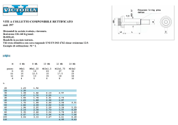
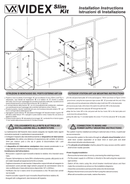
L'utensile deve essere assemblato ad una flangia regolabile, ha due
fascette rettificate (generalmente evidenziate con la scritta "T.I.R." in
disegno) come descritto qui sotto:
The tool to be connected with an adjustable flange has two ground
areas (showed usually with “T.I.R.” in blue print), as depicted:
HANNA dispone a magazzino o può costruire in breve tempo diversi
tipi di porta utensile con flangia regolabile.
HANNA maintain in stock or supply in short lead time, several tool
holders designs to be used with tools with radial / angular adjustable flange
connection.
DIN 69871 - AD+B - DIN norm 69871 - AD+B
T.I.R
Viti di Regolazione Radiale
Radial Adjustment Screws
Viti di Regolazione Angolare
Angular Adjustments Screws
T.I.R
Le flange con i due tipi di adduzione del refrigerante (AD= centrale più
B= laterale) possono essere usate per entrambi i tipi di mandrini.
L'operatore dovrà solo capire il corretto uso della forma AD o B a seconda
del tipo di macchina.
The DIN (ISO) V-flanges combine both coolant designs AD (central)
plus B (lateral) and so, can be used in both spindle types. The operator
must only check the correct use of the AD or B form, according the
machine.
ØD1
G1
Fascetta di Controllo
Angular Adjustment Strip
ØD
G
Fascetta di Controllo
Radial Adjustment Strip
Importante: l'utensile deve essere regolato/montato sulla macchina
che si utilizzerà per la lavorazione. Se dovesse essere utilizzato su un'altra
macchina utensile, la procedura di regolazione deve essere ripetuta.
Eseguite i seguenti passaggi per azzerare l'utensile.
(1) Montare l'utensile sull'adattatore flangia con le 4+4 viti (angolari-radiali)
per la regolazione allentate.
Important: The tool must be adjusted / zeroed assembled in the
machine spindle it runs with. If the spindle is changed (machine changed)
the adjustment must be reset. Follow the steps to zero the tool:
A
L
(1) Assembly the tool + holder with radial screws (4X) and angular screws
(4X) untightened;
(2) Give a gentle tightening on the clamp screws (4X);
(2 ) Serrare delicatamente le 4 viti di serraggio .
(3) Posizionare il comparatore sulla fascetta di controllo posteriore e
portare a zero l'eventuale errore di rotazione agendo sulle viti di
regolazione radiale.
(4) Quando si è sicuri che radialmente non vi sia errore, serrare fortemente
le quattro viti di fissaggio.
(5) Posizionare il comparatore sulla fascetta anteriore e portare
l'eventuale errore di rotazione a zero, agendo sulle viti di regolazione
angolare.
(6) Ritornare al punto 3 e controllare che sia a zero.
Note:
(1) Quando si esegue la regolazione angolare, agire solo su due viti di
regolazione.
(2) Dopo aver perfettamente regolato l'utensile, stringere leggermente le
due viti non utilizzate nella regolazione, per evitare che, svitandosi, si
perdano durante la lavorazione.
(3) Put an indicator (0,01mm) on the rear ground strip and zero the run-out
acting on the radial adjustment screws;
(4) Making sure the run-out is zeroed on the rear ground strip, tighten the
clamp screws firmly;
(5) Go with the indicator over the front ground strip and check the angular
run-out. Zero the run-out acting on the angular adjustment screws;
(6) Return to step (3) and recheck that the run-out is zeroed on the rear
(radial) strip.
Hints:
(1) When working on the angular adjustment (step 5) act only on two
adjacent screws.
(2) After the tool is zeroed, tighten gently the two angular screws not used,
in order they are not loose during the work.
40
40
40
40
40
60
70
80
100
117
44,45
44,45
44,45
44,45
44,45
50
50
55
60
60
118,4
118,4
123,4
128,4
128,4
M5
M6
M6
M8
M8
M8x1
M8x1
M8x1
M10x1
M10x1
1,3
1,4
1,7
2,2
2,5
075.0126-00
075.0151-00
075.0117-00
075.0133-00
075.0177-00
50
50
50
50
50
70
80
100
117
131,5
69,85
69,85
69,85
69,85
69,85
50
50
60
60
60
151,8
151,8
161,8
161,8
161,8
M6
M6
M8
M8
M8
M8x1
M8x1
M10x1
M10x1
M10x1
3,4
3,6
4,4
4,5
5,0
075.0105-00
075.0106-00
075.0096-00
075.0209-00
075.0186-00
Scarica