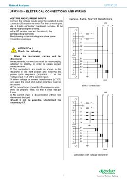
ELETTROTECNICA
VAR COMPENSATION – MAR 2004
LOW VOLTAGE POWER FACTOR CORRECTION
CAPACITORS AND EQUIPMENT STANDARD LIFE
SERIES
General information
DUCATI energia uses the name Standard Life, (SL), to define all capacitors
produced with metallized polypropylene technology.
Metallized polypropylene technology (PPM - MKP) utilizes the technique of
depositing, with vacuum evaporation, an extremely thin layer of metal on one
side of the polypropylene film.
The capacitive elements are obtained by winding two polypropylene films.
The plates of the capacitors are formed by the metallization of the two films and
the dielectric by the polypropylene film.
The most important feature of the capacitors with metallized plates is their
ability of self-regeneration.
This means that they are capable of restoring their electrical properties even
after the occurrence of a short circuit between the plates.
Due to the reduced thickness of the plates, the current generated by a short
circuit in the area of the fault is capable of vaporizing the metallization, thereby
automatically extinguishing the short circuit without an appreciable reduction
in capacity or expenditure of energy.
ing. Stefano Comuzzi – Sezione ELETTROTECNICA ed AUTOMAZIONE
Page 1 / 10
ELETTROTECNICA
VAR COMPENSATION – MAR 2004
To ensure protection, the capacitive elements that make up the unit are
individually fitted with an overpressure safety device.
The function of this device is to interrupt the short circuit when, at the end of its
useful life, the capacitor is no longer able to regenerate itself.
This device interrupts the connections of the terminal by using the internally
developed pressure resulting from the decomposition of the film due to the
overheating caused by the short circuit.
It should be noted that an external fuse is not as reliable since the current of the
short circuit, strongly limited by the metallization, is largely variable.
The capacitors produced with PPM technology are commonly known as “dry”
capacitors since the smooth surface of the film does not allow the air entrapped
during the winding process to be substituted with oil.
The impregnating agent in the SL series consists of a polyurethane resin, which
is more stable than the liquids eventually used for the filling and insulation of
the active part of the metallic capacitor.
The SL capacitors are built with environmentally friendly materials conforming
to reference standards IEC 831-1/2,EN 60831-1/2. Many models are certified by
institutes, all are manufactured fully complying the said standards’ requests.
ing. Stefano Comuzzi – Sezione ELETTROTECNICA ed AUTOMAZIONE
Page 2 / 10
ELETTROTECNICA
VAR COMPENSATION – MAR 2004
DEFINITIONS
Rated voltage (Un)
This is the maximum effective value of the alternate sinusoidal voltage for
which the capacitor was designed.
Rated power (Qn)
This is the reactive power delivered from the capacitor with the rated voltage
and frequency applied.
Rated capacitance (Cn)
This is the value which permits the delivery of the rated power applying the
rated voltage and frequency to the terminals.
Rated current (In)
This is the effective value of the alternate current that circulates in the capacitor
when the rated voltage and frequency are applied to the rated capacity.
ing. Stefano Comuzzi – Sezione ELETTROTECNICA ed AUTOMAZIONE
Page 3 / 10
ELETTROTECNICA
VAR COMPENSATION – MAR 2004
OPERATING CONDITIONS
Unlike most electrical equipment, power factor correction capacitors, each time
they are energized, continuously operate at full load or at loads which differ
from this value only as a consequence of variations in voltage and frequency.
Overstressing and overheating shorten the life span of the capacitor. For this
reason the operating conditions (temperature, voltage and current) must be
carefully controlled in order to obtain optimum results as respects the lifespan
of the capacitor.
Voltage
The capacitors are produced in accordance with reference standards IEC 8311/2, EN 60831-1/2 which regulate their manufacturing, testing, installation and
application and which indicate the following maximum values for overvoltage
applicable to the capacitors:
+10% for 8 hours every 24 hours
+15% for 30 minutes every 24 hours
+20% for 5 minutes every 24 hours
+30% for 1 minute every 24 hours.
Overvoltages in excess of 15% should not occur more than 200 times in the
lifespan of the capacitor.
Often when there is the presence of overload conditions during service, in the
presence of a moderate harmonic load for example, it is common to use
oversized capacitors in terms of voltage.
In such cases the output power at operating voltage will be reduced with
respect to that of the rated load. It is advisable to evaluate the reduction
experienced in the output power on the basis of the correlation between the
operating voltage and the rated voltage.
ing. Stefano Comuzzi – Sezione ELETTROTECNICA ed AUTOMAZIONE
Page 4 / 10
ELETTROTECNICA
VAR COMPENSATION – MAR 2004
The following table indicates the output power of a 100 kvar capacitor used on a
400 V network with a rated voltage of 450, 500, and 550 V.
Temperature
The temperature of the capacitor during operation is the parameter that, along
with the voltage, has the greatest influence on the life span of the capacitor. It is
important that the capacitor always be placed in a position where the cooling air
can freely circulate, avoiding the radiant heat of hot surfaces of other
components.
When the capacitors are placed in closed cabinets it is necessary to have air
vents which allow for an easy exchange of air between the interior and exterior
of the cabinet. On the other hand, when the degree of protection of the cabinet
does not permit this exchange of air, the internal spaces must be much larger
and the positioning of the capacitors must be carefully studied to permit the
necessary channels which allow for the circulation of cooling air.
In this case the forced cooling air will have to be provided by suitable fans. As a
rule the temperature of the cooling air inside the cabinet should not differ by
more than 5°C with respect to the external air at the control panel.
ing. Stefano Comuzzi – Sezione ELETTROTECNICA ed AUTOMAZIONE
Page 5 / 10
ELETTROTECNICA
VAR COMPENSATION – MAR 2004
Cooling air temperature
This is the temperature of cooling air measured at the hottest point of the bank
of capacitors, under working conditions, halfway between two capacitors or on
the surface of one of these.
Categories of ambient air temperature
This represents the range of cooling air temperatures in which the capacitor is
designed to operate. As a rule there are 4 categories represented by a number
and a letter or by two numbers as shown in the table.
The first number represents the minimum temperature of the cooling air at
which the capacitor can be energized (-25°C) on request -40°C. The letter or the
second number represents the upper limit of the temperature range and
precisely the max. value indicated in the table.
ing. Stefano Comuzzi – Sezione ELETTROTECNICA ed AUTOMAZIONE
Page 6 / 10
ELETTROTECNICA
VAR COMPENSATION – MAR 2004
Residual voltage
This is the voltage that remains after disconnecting the capacitor from the
network. This voltage must be eliminated in order to avoid dangerous
conditions for the operator. All three-phase capacitors are equipped with
discharge devices that reduce the residual voltage to a value of minimum 75 V
after 3 minutes.
It is important to bear in mind that the capacitors cannot be energized if there is
a residual voltage of more than 10% across them. Particular attention must
therefore be applied in harmonizing the capacitor discharge times with the
response times of the control devices (Regulators).
In cases where the lag time of the regulators are shorter than the discharge time
of the capacitor, it is necessary to provide additional discharge devices until the
connection occurs with a residual voltage of less than 10%.
To reduce the residual voltage to 50 V in 20 seconds in batteries with a power
less than or equal to 20 kvar at a voltage of 400 V, use 3 metal oxide resistors of
68 kohm, 4W in a delta connection.
Current
The capacitors are made to function continuously at an effective value of 1.3
times the value of the current at rated voltage and frequency.
Bearing in mind the capacitance tolerance, the maximum current can arrive to
1.5 In, the value to which it is necessary to refer in the scaling of the line of
control and protection devices. This overcurrent factor can be determined by the
combined effect of harmonics, overvoltages and capacitance tolerance.
ing. Stefano Comuzzi – Sezione ELETTROTECNICA ed AUTOMAZIONE
Page 7 / 10
ELETTROTECNICA
VAR COMPENSATION – MAR 2004
Max inrush current
Transient overcurrents having elevated amplitudes and high frequencies occur
when the capacitors are switched in to the circuit.
This is especially true when a bank of capacitors is put in a parallel connection
with other already-energized capacitors.
It may therefore be necessary to reduce these transient overcurrents to
acceptable values both for the capacitor and the contactor used by connecting
the capacitor using suitable devices (resistors or reactors) in the power circuit of
the battery.
The peak value of the overcurrent caused during manoeuvring operations must
be limited to a maximum value of 100 In (crest value of the 1st cycle).
ing. Stefano Comuzzi – Sezione ELETTROTECNICA ed AUTOMAZIONE
Page 8 / 10
ELETTROTECNICA
VAR COMPENSATION – MAR 2004
Complete the following phrases with the right answers
1)
The most important feature of the capacitors with metallized plates is their ability of
self-regeneration.
a)
thick
b) plastic
c)
metallized
d) rubber
2)
To ensure protection, the capacitive elements that make up the unit are individually
fitted with an overpressure safety device. The function of this device is to interrupt the short
circuit when, at the end of its useful life, the capacitor is no longer able to regenerate itself.
a)
underpressure
b) overpressure
c)
overvoltage
d) undercurrent
3)
The impregnating agent in the SL series consists of a polyurethane resin which is more
stable than the liquids eventually used for the filling and insulation of the active part of the
metallic capacitor.
a)
polyurethane
b) cheese
c)
paper
d) aluminium
4)
Definition of Rated voltage (Un): This is the maximum effective value of the alternate
sinusoidal voltage for which the capacitor was designed.
a)
effective value
b) real value
c)
value
d) efficient value
5)
Definition of Rated power (Qn): this is the reactive power delivered from the capacitor
with the rated voltage and frequency applied.
a)
capacitance
ing. Stefano Comuzzi – Sezione ELETTROTECNICA ed AUTOMAZIONE
Page 9 / 10
ELETTROTECNICA
VAR COMPENSATION – MAR 2004
b)
c)
d)
voltage and frequency
voltage
current and frequency
6)
Often when there is the presence of overload conditions during service, in the presence
of a moderate harmonic load (1) for example, it is common to use oversized (2) capacitors in
terms of voltage.
a)
load ………… …………strong
b) harmonic load …… ….. oversized
c)
load …………………… power
d) harmonic load ………… undersized
7)
The temperature of the capacitor during operation is the parameter that, along with the
voltage, has the greatest influence on the life span of the capacitor. It is important that the
capacitor always be placed in a position where the cooling air can freely circulate, avoiding
the radiant heat of hot surfaces of other components.
a)
Right ………………… cold surfaces of
b) in a position ……………… hot surfaces of
c)
horizontally……………… electric voltage of
d) in a closed box ……………big capacitance of
Fill the gaps
Residual voltage: this is the voltage that remains after (1) disconnecting the capacitor from
the network. This voltage must be (2) eliminated in order to avoid dangerous conditions for
the operator. All (3) three-phase capacitors are equipped with discharge devices, which
reduce the (4) residual voltage to a value of minimum 75 V after 3 minutes.
It is important to bear in mind that the (5) capacitors cannot be energized if there is a residual
(6) voltage of more than 10% across them. Particular attention must therefore be applied in
harmonizing the capacitor (7) discharge times with the response times of the control devices
(Regulators).
discharge voltage capacitors residual eliminated disconnecting three-phase
ing. Stefano Comuzzi – Sezione ELETTROTECNICA ed AUTOMAZIONE
Page 10 / 10
Scarica