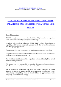
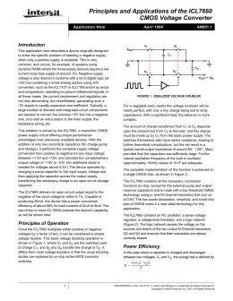
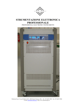
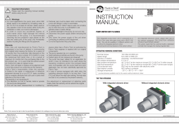
UPM3100
UPM3100 – ELETTRICAL CONNECTIONS AND WIRING
VOLTAGE AND CURRENT INPUTS
Connect the voltage inputs using the supplied 4-pole
connector (European version). For the current inputs,
use a 6-pole connector (European version), to be
fixed by tightening the screws.
In the US version, connect the wires to the
corresponding terminals.
The following schematic diagrams show some
connection examples.
3-phase, 4-wire, 3current transformers
ATTENTION !
Check the following:
1 When the instrument carries out bidirectional
measurements, connections must be made paying
attention to polarity, in order to obtain correct
measurements.
2 The connections are made as shown in the
diagrams in the next section and following the
phase cycle sequence (important:: L1 of the
voltage input = L1 of the current input).
3 When voltage or current transformers (VT/CT)
are used, the input and output polarities must be
respected.
4 The current input connector (European version)
must be properly fixed, so that it does not get
loose.
5 No current input is disconnected without first
disconnect the load.
Should it not be possible, shortcircuit the
secondary CT.
direct connection
connection with voltage trasformer
1
UPM3100
3-phase, 3-wire, 3 current transformers
3-phase, 3-wire, 2 current transformers
direct connection
direct connection
connection with voltage trasformer
connection with voltage trasformer
2
UPM3100
3-phase, 3-wire, 1 current transformer
3-phase, 1 Volt, 3 current transformers
direct connection
direct connection
connection with voltage trasformer
connection with voltage trasformer
3
UPM3100
Single phase - 3 wires (L1-L2)
Single phase (L1)
direct connection
direct connection
connection with voltage trasformer
connection with voltage trasformer
4
UPM3100
7.5.1 Voltage specifications
The standard voltage specifications are listed below:
NOTE
The label on the meter defines the real configuration
Input voltage
Input impedance
Load
750 Vca max L-L
> 1.3 MOhm
max 0.15 VA per phase @ 750 VAC
7.5.2 Current specifications
The phase and polarity of the input current are an essential parameters for a proper instrument operation.
The stardard current specifications are listed below:
NOTE
The label on the meter defines the real configuration
Rated input current
Input impedance
Burden
Insulation voltage
1 / 5A, programmable
circa 0.02 Ohm
max 0.15 VA per phase @ 5A
max 150VRMS between phases
NOTES:
- Extract from manual (1IAUX3100003)
- Subject to change without notice
5
Scarica