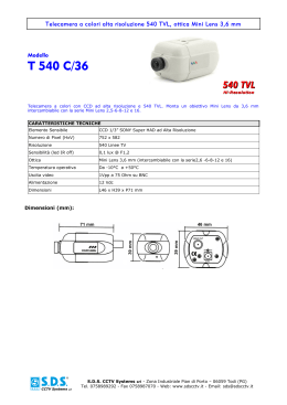
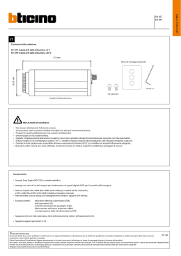
Manuale Di Istruziono. User Manuall LE03726AB -01CB-12W40 391697 391699 IT Fare riferimento alla figura precedente e alla guida di configurazione seguente: 1- Rimuovere il coperchio dalla sommità dell'attacco dell'obiettivo. 2- Avvitare l'obiettivo nel relativo attacco. 3- Collegare l'uscita video (10) al monitor o a un altro dispositivo video con un cavo coassiale da 75 ohm. 4- Collegare la sorgente di alimentazione (7), CA con il cavo di alimentazione o CC usando il jack DC (+12 V CC, si trova al centro della presa del jack), si accenderà l'indicatore LED (3). 5- Dopo che l'immagine compare sul monitor, regolare la messa a fuoco e il diaframma dell'obiettivo per migliorare l'immagine. 6- Se il soggetto non risulta messo a fuoco dopo aver regolato l'obiettivo, regolare nuovamente la messa a fuoco come segue: impostare l'anello di messa a fuoco dell'obiettivo su infinito (∞) acquisire l'immagine del soggetto a una distanza superiore a 20 metri allentare la vite che fissa l'attacco dell'obiettivo (usando la chiave a brugola) ruotare l'obiettivo e fissarlo nel relativo attacco in modo che il soggetto risulti messo a fuoco e l'immagine chiara serrare la vite che fissa l'attacco dell'obiettivo (2). 7- Montare la staffa di supporto nel foro (1) in alto o in basso sulla telecamera, usando il blocco di montaggio da 8 mm fornito con le 2 viti in dotazione. 8- Funzione auto-iris Quando si usa una lente con iride automatica, SW1 (9) deve trovarsi in posizione "IA/IM" per disabilitare la funzione OEA. Prima di inserire i 4 pin miniatura forniti nel connettore dell'auto-iris (4), controllare il tipo di obiettivo auto-iris usato e la compatibilità con le polarità. Quando si usa la lente con iride automatica dell'azionamento DC (o dell'azionamento diretto), lo switch (5) deve trovarsi in posizione "Azionamento DC". Regolare VR (6) al livello adeguato. Quando si usa la lente con iride automatica dell'azionamento video lo switch (5) deve trovarsi in posizione "Video DR". Quando si usa una lente con diaframma manuale, lo switch SW1 (9) è selezionabile in base all'ambiente di applicazione. 9- Quando si usa la funzione CRI (compensazione della retroilluminazione), lo switch SW2 (8) deve trovarsi in posizione "CRI". Specifiche Specifiche Sensore Risoluzione orizzontale Scansione Giorno/Notte Illuminazione minima ICR (IR Cut Filter) Distanza di illuminazione infrarossi (IR) Angolo di illuminazione infrarossi (IR) OSD (On-Screen Display) WDR (Wide Dynamic Range) Mascheratura Obiettivo/Attacco obiettivo Grado di protezione IP Tensione di alimentazione Consumo Temperatura di esercizio Dimensioni del prodotto Peso del prodotto 2 391697 391699 1/3" a colori ad alta risoluzione PAL: 540 TVL Interlacciata Sì 0,1 lux a F1,2 No No No No CS 12 V CC (+ -) 10% 110 – 230 V~ 12 V = 100 mA 230 V~ 5 mA (1 W) Da -10°C a 50°C 115 mm x 50,20 mm x 42,20 mm 215 g 235 g Manuale Di Istruziono Installazione e funzionamento EN 3 User Manual Installation and operation Please refer to figure above and setup guide below: 10- Remove the cap cover from the top of the lens mount. 11- Screw the lens into the lens mount. 12- Connect the video output (10) to the monitor or other video device through a 75 Ohms type coaxial cable. 13- Connect the power source (7), AC with the power cord, or DC by using the DC Jack (+12V DC is in the center of the jack plug), then the LED indicator (3) will lit. 14- Once the picture appears on the monitor, adjust the focus and iris of the lens to obtain the best picture. 15- When the subject is not in focus after adjusting the focus of the lens, adjust the back focus as follows: 4FUUIFMFOTGPDVTSJOHUPJOGJOJUZž Take picture of the subject at a distance more than 20M away. Loosen the screw securing the lens mount (use L-wrench). Turn the lens and secure it to the lens mount so that the subject is in focus and the picture is clear. Tighten the screw securing the lens mount (2). 16- Mount the mounting bracket to hole (1) on the top or bottom of the camera, using the enclosed 8mm mounting block with 2 screws furnished. 17- Auto Iris Function When using an auto iris lens, SW1 (9) should be in the “AI/ MI” position to disable AES function. Before plugging the enclosed miniature 4 pins to the auto iris connector (4), please check the type of auto iris lens used, and also the compatibility on the polarities. When using DC Drive auto iris lens is used (or Direct Drive), the switch (5) should be in the “DC Drive” position. Adjust VR (6) to the proper level. When Video Drive auto iris lens is used, the switch (5) should be in the “Video DR” position. When using manual iris lens, the switch SW1 (9) is select-able depending on the application environment. 18- When using the BLC (Back Light Compensation) function, the switch SW2 (8) should be in position with “BLC”. Specifications Specifications Sensor Horizontal resolution Scanning Day/Night Minimum illumination ICR (IR Cut Filter) Infrared (IR) light distance Infrared (IR) light angle OSD (On Screen Display) WDR (Wide Dynamic Range) Masking Lens / Lens mount IP degree of protection Power supply voltage Power consumption Operating temperature Product dimensions Product weight 4 391697 391699 1/3" Color Hi-Res PAL : 540 TVL Interlaced Yes 0.1 [email protected] No No No No CS 12 VDC (+ -)10% 110 – 230 V~ 12 V = 100 mA , 230 V~ 5 mA (1 W) De -10 °C à 50 °C 115 mm x 50,20 mm x 42,20 mm 215 g 235 g
Scarica