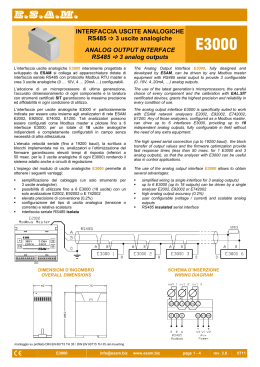
E.S.A.M.
INTERFACCIA SERIALE ASINCRONA
RS485
ASYNCRONOUS SERIAL INTERFACE
Modbus RTU
RS485
I convertitori ESAM della serie MT possono essere dotati di
interfaccia seriale isolata RS485 con protocollo Modbus RTU
ESAM MT series transducers can be supplied with RS485
insulated serial interface with Modbus RTU protocol
Porta seriale:
Serial port:
- RS485 HALF DUPLEX
- Baud rate: 1200, 2400, 4800, 9600, 19200
- I parametri N (nessuna parità), 1 (start bit), 8 (bit per dato)
e 1 (stop bit) sono fissi.
- RS485 HALF DUPLEX
- Baud rate: 1200, 2400, 4800, 9600, 19200
- the parameters N (no parity), 1 (start bit), 8 (data bit)
and 1 (stop bit) are fixed.
Funzioni Modbus RTU implementate:
Modbus RTU functions implemented:
- 03 read holding registers
Si possono leggere fino a 24 word per volta.
Per leggere un valore in floating point (2 word) si devono
leggere le due word con una singola richiesta. Se l’indirizzo
iniziale o finale cade in mezzo a un valore floating point
verrà mandato un codice di errore (illegal address).
- 03 read holding registers
Up to 24 words of contiguous data can be retrieved at a
time. When reading floating point values (2 words), both
words must be read with a single command. If the Initial or
the final address falls in the middle of a floating point value, the
instrument sends an exception response (illegal address).
- 06 preset single register
Questo comando funziona solo con valori interi.
Per valori in floating point usare “preset multiple register”
- 06 preset single register
This command works only with integer values. Floating point
values must be written with “preset multiple registers”
- 16 preset multiple register
Questo comando è utilizzato per scrivere un valore floating
point (2 word). E’ utilizzabile anche per scrivere un valore
intero (1 word)
Si può scrivere un solo valore intero o floating point alla volta
- 16 preset multiple register
This command is intended to write a floating point value
(2 words).Can be used also to write an integer value (1 word)
Only a single value at a time can be written (float or integer).
Dati:
La comunicazione seriale avviene tramite la trasmissione di
parole binarie di 16 bit (word).I dati sono di due tipi: interi
(composti da una sola word) e floating point - float - (formati da
2 word).
Esempio
Per leggere le prime tre misure partendo dal registro Modbus
100. si dovranno chiedere 6 word, quindi i registri da 100 a 105.
Data:
Data are transmitted as 16 bit words. There are two basic types
of data: integer values (16 bits, 1 word) and floating point values
(32 bits, 2 words).
Example
To read 3 measured values starting register 100, 6 words are
required, that is from register 100 to 105.
Valore floating point:
I valori floating point seguono la specifica IEEE 32 bit floating
point standard
Floating point value:
The IEEE standard single precision format for real numbers
A value is coded in 32 bit as follows:
MSB
LSB
seeeeeee : emmmmmmm : mmmmmmmm : mmmmmmmm
word A
word B
s segno del numero 0 positivo 1 negativo
e esponente a 8 bit
m mantissa del numero 23 bit
s Sign bit. ”0” If the value is positive, “1”.If the value is negative
e 8 bit exponent
m The mantissa which is code in 23 bits.
Comando SWFP: Impostando 0 si riceverà prima la word A e
poi la word B; impostando 1 prima la word B e poi la word A
SWFP Command: Setting to 0 word A will be sent before
word B; setting 1 word B will be sent before word A.
Codici di errore Modbus RTU implementati:
Modbus RTU implemented exception codes:
- 1 illegal function - provocato da una richiesta non valida.
- 1illegal function - caused by a non valid request.
- 2 illegal data address - provocato dalla richiesta di lettura o
scrittura di un indirizzo non valido.
Es. Voler leggere un valore floating point chiedendo una
sola word.
- 2 illegal data address - caused by the request of reading or
- writing of a invalid address.
Ex. Read a floating point value asking only a word.
- 3 illegal data value - caused by the writing of an invalid value.
- 3 illegal data value - provocato dalla scrittura di un valore non
valido.
)
[email protected]
www.esam.biz
page 1 - 5
rev. 1.3
05.13
E.S.A.M.
Modelli
Misure disponibile
Models
Available measured values
Ptot
MT-PA ...
MT-PR …
MT-PAR …
MT-PS …
MT-PF …
MT-PFAR ...
MT-C3
MT-C256
MT-CaFP ...
MT-V3FF
MT-V3FN
MT-V256
MT-CV256
MT-PACV256
MT-CVF256
MT-Vdc
MT-Cdc
MT-Pdc
MT-F
MT-FT
MT-LF
MT-FE
MT-Pt
MT-R
MT-S ...
Stot
PF
PFtr
V1
V2
V3
V12
V23
V31
I1
I2
I3
IFP
Vdc
Idc
Pdc
Freq
FE
FT
RTD
R
Sum
Ao1
3
3
3
3
3
3
3
3
3
3
3
3
3
3
3
3
3
3
3
3
3
3
3
3
3
3
3
3
3
3
3
3
3
3
3
3
3
3
3
3
3
3
3
3
3
3
3
3
3
3
3
3
3
3
3
3
3
3
3
3
3
3
3
3
3
3
3
3
P1
MT-UN1
MT-UN31
MT-UN32
MT-UN41
MT-UN43
Qtot
Uscite
analogiche
Analog
outputs
3
P2
3
P3
Ptot
3
3
3
3
3
3
)
Q1
3
Q2
3
Ao2
Ao3
3
3
3
3
3
3
3
3
3
3
3
3
3
3
Q3
Qtot
PF
PFtr
Stot
Pulse 1
Pulse 2
Ao1
Ao2
Ao3
3
3
3
3
3
3
3
3
3
3
3
3
3
3
3
3
3
3
3
3
3
3
3
3
3
3
3
3
3
3
3
3
3
3
3
3
3
3
3
3
3
3
3
3
3
3
[email protected]
www.esam.biz
page 2- 5
rev. 1.3
05.13
E.S.A.M.
Elenco registri Modbus RTU
Modbus RTU registers list
Registro
Register
100-101
100-101
100-101
100-101
100-101
100-101
102-103
102-103
104-105
104-105
106-107
107-108
108-109
108-109
110-111
112-113
114-115
116-117
118-119
120-121
122-123
124-125
126-127
128-129
130-131
132-133
134-135
136-137
138-139
140-141
Tipo
Type
Float
Float
Float
Float
Float
Float
Float
Float
Float
Float
Float
Float
Float
Float
Float
Float
Float
Float
Float
Float
Float
Float
Float
Float
Float
Float
Float
Float
Float
Float
Read / Write
Read / Write
Read only
Read only
Read only
Read only
Read only
Read only
Read only
Read only
Read only
Read only
Read only
Read only
Read only
Read only
Read only
Read only
Read only
Read only
Read only
Read only
Read only
Read only
Read only
Read only
Read only
Read only
Read only
Read only
Read only
Read only
Simbolo
Symbol
Freq
FT
FE
Sum
Vdc
P1
P2
Cdc
Pdc
P3
R
Q1
RTD
Q2
Q3
Ptot
Qtot
SPtot
PFtr
PF
V1
V2
V3
I1
I2
I3
V12
V23
V31
IFP
frequenza / frequency
frequenza tachimetrica / tachymetric frequency
impulsi encoder / encoder pulses
sommatore / summing
tensione continua / direct voltage
potenza attiva fase 1 / active power phase 1
potenza attiva fase 2 / active power phase 2
corrente continua / direct current
potenza corrente continua / d.c. power
potenza attiva fase 3 / active power phase 3
resistenza / resistance
potenza reattiva fase 1 / reactive power phase 1
temperatura / temperature
potenza reattiva fase 2 / reactive power phase 2
potenza reattiva fase 3 / reactive power phase 3
potenza attiva totale / total active power (P1+P2+P3)
potenza reattiva totale / total reactive power (Q1+Q2+Q3)
potenza apparente totale / total apparent power (√P²+Q²)
fattore di potenza trifase trigonometrico / trigonometric 3-phase power factor
fattore di potenza trifase con segno / signed 3-ph. power factor ( + ind. , - cap.)
tensione RMS fase 1 / RMS phase 1 to neutral voltage
tensione RMS fase 2 / RMS phase 2 to neutral voltage
tensione RMS fase 3 / RMS phase 3 to neutral voltage
corrente RMS fase 1 / RMS current phase 1
corrente RMS fase 2 / RMS current phase 2
corrente RMS fase 3 / RMS current phase 3
tensione concatenata RMS fasi 1 e 2 / RMS linked voltage phase 1 and 2
tensione concatenata RMS fasi 2 e 3 / RMS linked voltage phase 2 and 3
tensione concatenata RMS fasi 3 e 1 / RMS linked voltage phase 3 and 1
corrente fase 1 con rilievo polarità / current phase 1 with polarity detection
200
201
203
Int
Float
Int
Read / Write
Read / Write
Read / Write
PoN
R0
EUT
tipo di RTD Platino o Nichel / kind of RTD Platinum or Nichel (0=Pt, 1=Ni)
Resistenza RTD a 0°C (default 100Ω) / RTD resistance at 0°C (deafult 100°C)
unità di misura / measure unit 0=°C, 1=°F, 2=°K
300-301
302-303
304-305
305-306
308
309
310
311
312
313
314-315
316-317
318
319
320
321-322
323-324
325
326
327
328-329
330-331
332
333
334
335-336
337-338
Float
Float
Float
Float
Int
Int
Int
Int
Int
Int
Float
Float
Int
Int
Int
Float
Float
Int
Int
Int
Float
Float
Int
Int
Int
Float
Float
Read only
Read only
Read / Write
Read / Write
Read only
Read / Write
Read / Write
Read / Write
Read / Write
Read / Write
Read / Write
Read / Write
Read / Write
Read / Write
Read / Write
Read / Write
Read / Write
Read / Write
Read / Write
Read / Write
Read / Write
Read / Write
Read / Write
Read / Write
Read / Write
Read / Write
Read / Write
FSI
FSV
CTR
VTR
HWCFG
AVG
Pulse 1
Pulse 2
TPO1
TPO2
WPO1
WPO2
AoC1
AoLW1
AoS1
AoLR1
AoHR1
AoC2
AoLW2
AoS2
AoLR2
AoHR2
AoC3
AoLW3
AoS3
AoLR3
AoHR3
corrente: fondo scala o ingresso nominale / current: full-scale or rated input
tensione: fondo scala o ingresso nominale / voltage: full-scale or rated input
rapporto TA esterno/ external CT ratio
rapporto TV esterno / external VT ratio
configurazione hardware / hardware configuration
tempo di risposta / response time (es. 1<70, 2<100, 3<200...6<500...12<1000
grandezza da associare a Pulse 1 / variable to associate to Pulse 1
Table 4
grandezza da associare a Pulse 2 / variable to associate to Pulse 2
Table 4
durata Pulse 1 / timing of Pulse 1 (valore default / default value 100 msec.)
durata Pulse 2 / timing of Pulse 2 (valore default / default value 100 msec.)
peso Pulse 1 / weight of Pulse 1
peso Pulse 2 / weight of Pulse 2
tipo di uscita analogica (V o mA) / kind of analog output (V or mA)
Table 2
uscita 1 diretta o inversa / direct or reverse output 1
grandezza da associare all’ uscita 1 / variable to associate to output 1 Table 1
inizio scala uscita analogica 1 / start scale analog output 1
fondo scala uscita analogica 1 / full scale analog output 1
tipo di uscita analogica (V o mA) / kind of analog output (V or mA)
Table 2
uscita 2 diretta o inversa / direct or reverse output 2
grandezza da associare all’ uscita 2 / variable to associate to output 2 Table 1
inizio scala uscita analogica 2 / start scale analog output 2
fondo scala uscita analogica 2 / full scale analog output 2
tipo di uscita analogica (V o mA) / kind of analog output (V or mA)
Table 2
uscita 3 diretta o inversa / direct or reverse output 3
grandezza da associare all’ uscita 3 / variable to associate to output 3 Table 1
inizio scala uscita analogica 3 / start scale analog output 3
fondo scala uscita analogica 3 / full scale analog output 3
)
Descrizione
Description
[email protected]
www.esam.biz
Valori
Values
page 3- 5
Unità
Unit
Hz
RPM
V
W
W
A
W
W
Ω
VAR
°C
VAR
VAR
W
VAR
VA
Φ
Φ
V
V
V
A
A
A
V
V
V
(±) A
0…1
0…1...2
A
V
1…99999
1…99999
1…20
0…4
0…4
10…255
10…255
A
V
msec
msec
msec
0...1
0…32
0…1
0…32
0…1
0…32
rev. 1.3
05.13
E.S.A.M.
Elenco registri Modbus RTU
Modbus RTU registers list
Registro
Register
500
501
502
503
600
601
602-603
604-605
Tipo
Type
Int
Int
Int
Int
Int
Read / Write
Read / Write
Read / Write
Read / Write
Read / Write
Read / Write
Read only
Simbolo
Symbol
NUMT
BAUD
XDEL
SWFP
VSW
Descrizione
Description
indirizzo di stazione / station address
baud rate - velocità seriale / baud rate
Table 3
minimo ritardo alla risposta / minimum delay before reply
Floating point: scambio ordine word A e B / float swap word A and B order.
versione firmware ( x100) / firmware release (x100), VSW: 3.40 → 340
Int
Read only
Read only
Read only
MODEL
SN03
SN47
modello del convertitore / transducer’s model
numero di serie (byte 0…3) / serial number (byte 0…3)
numero di serie (byte 4…7) / serial number (byte 4…7)
4 Char
4 Char
0
1
2
3
4
5
6
7
7
8
9
10
11
12
13
19
20
21
22
23
24
25
26
27
28
29
30
30
30
30
31
32
Simbolo
Symbol
NONE
P1
P2
P3
Q1
Q2
Q3
Pdc
Ptot
Qtot
Stot
PFtr
PF
s(Q)xPF
Unità
Unit
msec
Table 2
Table 1
Valori AOS
AOS values
Valori
Values
1…255
1…5
0…255
0…1
Descrizione
Description
uscita analogica disabilitata / analog output disabled
potenza attiva fase 1 / active power phase 1
potenza attiva fase 2 / active power phase 2
potenza attiva fase 3 / active power phase 3
potenza reattiva fase 1 / reactive power phase 1
potenza reattiva fase 2 / reactive power phase 2
potenza reattiva fase 3 / reactive power phase 3
potenza corrente continua / d.c. power
potenza attiva totale / total active power (P1+P2+P3)
potenza reattiva totale / total reactive power (Q1+Q2+Q3)
potenza apparente totale / total apparent power (√P²+Q²)
fattore di potenza trifase trigonometrico / trigonometric 3-phase power factor
fattore di potenza trifase con segno / signed 3-phase. power factor
s(Q) x PF
Valori
Values
0
1
2
4
5
6
8
9
10
Tipo di uscita
Kind of output
0…20mA
0…10mA
0…5mA
4…20mA
2…10mA
1…5mA
0…±20mA
0…±10mA
0…±5 mA
64
68
72
0…10V
2…10V
0…±10V
s(Q)x(2xPF-1)
V1
V2
V3
I1
I2
I3
V12
V23
s(Q) x (2 x PF-1)
tensione RMS fase 1 / RMS phase 1 to neutral voltage
tensione RMS fase 2 / RMS phase 2 to neutral voltage
tensione RMS fase 3 / RMS phase 3 to neutral voltage
corrente RMS fase 1 / RMS current phase 1
corrente RMS fase 2 / RMS current phase 2
corrente RMS fase 3 / RMS current phase 3
tensione oncatenate RMS fasi 1 e 2 / RMS linked voltage phase 1 and 2
tensione concatenata RMS fasi 2 e 3 / RMS linked voltage phase 2 and 3
Valori
Values
1
2
3
4
5
V31
Vdc
Cdc
Freq
FT
FE
R
RTD
IFP
tensione concatenata RMS fasi 3 e 1 / RMS linked voltage phase 3 and 1
tensione continua / direct voltage
corrente continua / direct current
frequenza / frequency
frequenza tachimetrica / tachymetric frequency
impulsi encoder / encoder pulses
resistenza / resistance
temperatura RTD / temperature RTD
corrente fase 1 con rilievo polarità / current phase 1 with polarity detection
Valori
Values
0
1
2
3
4
Table 3
Baud rate
Baud rate
1200
2400
4800
9600
19200
default
Table 4
Grandezza
Variable
--Wh+
WhVARh+
VARh-
NOTE SUL COLLEGAMENTO SERIALE / NOTE ABOUT SERIAL NETWORK
INSERZIONI CORRETTE / CORRECT INSERTIONS
)
[email protected]
www.esam.biz
page 4 - 5
rev. 1.2
06.11
E.S.A.M.
INSERZIONE ERRATA / WRONG INSERTION
Nota:
Il collegamento indicato con 0À è da effettuare
solo con SLAVE isolati
(Come tutti gli strumenti ESAM con seriale RS485 e
protocollo Modbus RTU)
Note:
The connection marked with 0À is possible
only with insulated SLAVE
(As all ESAM meters with serial RS485 and
Modbus RTU protocol )
L’interfaccia seriale RS485 è basata su una linea di comunicazione
differenziale bilanciata, impedenza tipica: 120Ω. La lunghezza massima
del collegamento non è definita ma dipende dalla velocità
comunicazione, dal rapporto segnale disturbo, dalla qualità del cavo. Si
fissa generalmente a 1200 metri la lunghezza massima.
Il cavo di collegamento può essere non schermato se la distanza è di
qualche metro in ambiente elettricamente poco “rumoroso”. Per distanze
comprese tra 15 e 100 metri è possibile usare un cavo schermato e
twistato senza particolari caratteristiche, mentre per i collegamenti oltre
100 metri è consigliabile utilizzare ad esempio cavo CEAM CPR 6003 o
BELDEN 9841.
La linea di comunicazione dovrà essere di tipo a catena evitando
configurazioni a stella e limitando le derivazioni a pochi metri (ved.
figure). Sull’ultimo slave della catena (es. SLAVE 32) dovrà essere
inserita in parallelo una resistenza di terminazione (valore tipico 120Ω).
Lo schermo del cavo utilizzato dovrà essere collegato, oltre al morsetto 0
del MT232485, a terra da un lato (preferibilmente lato master).
The RS485 serial interface is based on a differential balanced
communication line with a typical impedance of 120 ohms.
The maximum achievable length of the link depends on communication
speed, signal to noise ratio and cable quality: it is generally specified as
1200 meters.
An unshielded twisted pair can be used on short distances if the
electrical environment is not too noisy.
For distances between 15 and 100 meters any shielded twisted pair will
work, but for longer links a high quality low loss cable like CEAN CPR
6003 or BELDEN 9841 is suggested.
All the slaves should be arranged along the line; star connections must
be avoided and line branches, if any, must be kept short (see figures). A
termination resistor (typical value 120 ohm) must be inserted in parallel
with the last slave at the end of the line.
The cable shield must be connected to the 0 terminals and grounded at
one point only (preferably on master side).
Quando la comunicazione Modbus non funziona:
When Modbus communication doesn’t work:
1)
1)
Provare con una rete Modbus semplice, un master e uno slave:
controllare il cablaggio sia corretto, ovvero che A, B e 0 del master
siano collegati ai rispettivi A, B e 0 dello slave
2) Verificare che i parametri base di comunicazione del master siano:
8 bit, 1 stop bit, bit di parità assente, e che il baud rate sia lo stesso
dello slave
3) Verificare che l’indirizzo assegnato allo slave sia quello che il
master cerca di interrogare
4) Se si utilizza un convertitore RS232/485, verificare che si commuti
in ricezione prima che lo slave abbia iniziato ad inviare la risposta
5) Se la rete smette di funzionare quando si aggiunge uno slave,
controllare che l’ultimo slave aggiunto non abbia A e B invertiti o lo
stesso indirizzo di un altro slave già collegato.
6) Le variabili float devono essere lette o scritte con un singolo
comando Modbus: non e’ possibile leggere o scrivere “mezzo float”.
7) Per specifica del protocollo i registri Modbus (quelli scritti nel
manuale dello strumento) si contano a partire da 1, ma gli indirizzi
dei registri si contano da 0. Ciò significa che per chiedere la
variabile che si trova nel registro 100 sulla linea seriale viaggia il
numero 99. Il software dell’unita’ master dovrebbe provvedere a
inviare 99 quando gli si chiede il registro 100, in modo che per
l’utente tutto sia trasparente. Se così non fosse impostare nel
master il numero del registro – 1 (cioè in questo esempio 99).
8) Negli strumenti ESAM la richiesta di un blocco di holding registers
(modbus funzione 3) deve essere limitata a 24 word (12 variabili
float): gli indirizzi iniziale e finale non devono cadere a metà di una
variabile float.
9) Negli strumenti ESAM la scrittura in blocco di holding registers
(modbus funzione 16) e’ limitata a 2 word, ovvero una variabile
float.
10) Se si ricevono numeri senza senso, verificare che l’ordine in cui lo
slave invia le due word che compongono le variabili float sia quello
che il master sia aspetta. In caso contrario impostare diversamente
il master o lo slave.
11) In caso di malfunzionamento solo in campo, verificare che la rete
RS485 sia cablata a regola d’arte, soprattutto in caso di
collegamenti di lunghezza elevata e con molti slave connessi alla
rete: usare doppino schermato di buona qualità, collegare la calza
al terminale 0 degli slave, mettere eventualmente la calza a terra in
un unico punto (ad esempio sul master), evitare diramazioni della
linea e collegamenti “a stella”, montare l’appropriata resistenza di
terminazione (120 ohm) ai due estremi della linea.
E.S.A.M. unicenter s.r.l.
Elettronica Strumenti Apparecchiature Misura
Try a simple Modbus network, just one master and one slave:
check wiring, that is master A,B,0 terminals properly connected to
slave A,B,0.
2) Check master communication parameters: they must be 8 data
bits, 1 stop bit, no parity, baud rate the same of the slave
3) Check if the address of the slave is the one the master is trying to
access.
4) If you are using a RS232/RS485 converter, verify that it properly
switches in receive mode before the slave starts sending its reply.
5) If the network stops working when you add a slave, check if the
slave is properly wired and if its address is not the same of
another slave already connected
6) Floating point variables must be read and written with a single
Modbus command: it is not possible to read or write one half of a
float.
7) According to Modbus specification, Modbus registers (that is those
listed on the instruction manual) are counted starting from 1, while
their addresses starts from 0. This means that when you ask for
register 100 the actual number which the master must send on the
line is 99. The master should deal with this in a transparent way
for the user: if not, you have to modify master setup entering
register number – 1 (in this example 99)
8) ESAM instruments implement Modbus function 3 (read holding
registers) up to a maximum of 24 words (12 floating point
variables): initial and final addresses of the block must not be in
the middle of a float.
9) ESAM instruments implement Modbus function 16 (preset multiple
registers) only for 2 words, that is 1 floating point value.
10) If the master is receiving meaningless numbers, check if the slave
sends the two words of a float in the same order as the master is
expecting. If not change setup either in the master or in the slave
11) If you experience network malfunctioning in field only, verify the
layout of the RS485 line. Use high quality shielded pairs, always
connect 0 terminals, ground the shield in one point only, avoid line
branches and star topologies, put the 120 ohm termination
resistance at the end of the line. All this is most important with
long lines and many slaves connected.
20010 Bareggio (MI) Italia – Via S. Pietro, 10
Tel. 02.903.61.297 (3 l.r.a.) – Fax 02.903.62.314
Scarica