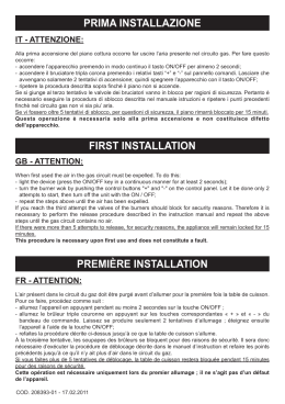
PA-702
PROFESSIONAL PREAMPLIFIER
Vorverstärker
Preamplificador
Préamplificateur
Preamplificatore
Operations Manual
Bedienungsanleltung
Manual de funcionamiento
Manual de fonctionnement
Manual del utente
Multi Language Instructions
English.................................................................................Page 3
Deutsch...........................................................................Page 4
Español...........................................................................Page 5
Francais..........................................................................Page 6
Italiano.............................................................................Page 7
1
12 13 14 15
11
5
4
10
9
8
7
2
6
Page 2
23
PHONO CD
GND
TUNER AUX
TAPE
PLAY REC
OUTPUT
2
1
GROUND LIFT
L
115
R
LIFT
16
17
18
19
20
21
22
25
24
3
7. BALANCE: Use this control to adjust the relative levels of the left and right
channels. The 12 o’clock position is the point of equal BALANCE (7).
INTRODUCTION
Congratulations on purchasing a GEMINI model PA-702 rack mountable
preamplifier. This state of the art unit includes the latest features backed by a
three year warranty. Prior to use, we suggest that you carefully read all the
instructions.
CAUTIONS
8. TREBLE: The TREBLE (8) control adjusts the relative level of the high
frequencies in the sound.
9. MID: The MID (9) control adjusts the relative level of the mid range
frequencies in the sound.
10.BASS: The BASS (10) control adjusts the relative level of the low
frequencies in the sound.
1. All operating instructions should be read before using this equipment.
2. To reduce the risk of electrical shock, do not open the unit. There are NO
USER REPLACEABLE PARTS INSIDE. Please refer servicing to a qualified
service technician.
3. Do not expose this unit to direct sunlight or to a heat source such as a
radiator or stove.
4. This unit should be cleaned only with a damp cloth. Avoid solvents or other
cleaning detergents.
5. When moving this equipment, it should be placed in its original carton and
packaging. This will reduce the risk of damage during transit.
6. DO NOT EXPOSE THIS UNIT TO RAIN OR MOISTURE.
7. DO NOT USE ANY SPRAY CLEANER OR LUBRICANT ON ANY CONTROLS
OR SWITCHES.
CONNECTION
1. Be sure the POWER (1) switch is in the OFF position. All connections must
be made with all equipment OFF.
11. PHONE JACK: 1/4" headphone input jack (11).
12.MONO: When the MONO (12) button is activated (LED is lit), the two
stereo channels are blended together to produce monophonic sound. This
blend minimizes rumble and surface noise in old monophonic records.
Push the button a second time (LED goes out) to get back to stereo mode.
13.MUTE: Pushing this button reduces the volume of the amplifier output
signal by approximately 20 dB. Pressing the button a second time removes
the muting. The MUTE (13) has no effect on the microphone volume.
14.LOW CUT: The output from a turntable usually contains strong but
inaudible impulses at infrasonic frequencies (below 20Hz) due to disc
warps, stylus/tonearm resonance, and vibrations that reach the turntable.
If these are amplified at full strength, they may waste amplifier power and
muddy the sound. The LOW CUT FILTER (14) attenuates these unwanted
signals.
15.LOUDNESS: When pressed, the LOUDNESS (15) button engages a
“loudness compensation” circuit which, at low-to-medium volume, boosts
the bass and treble response.
2 . For best sound, use only high quality RCA cables when hooking up
equipment to the PA-702. Make sure that all cables are pushed in securely.
3. Connect the OUTPUT LINE (22) jacks of the PA-702 to your amplifier(s).
4. Plug your microphone into the MIC (5) jack on the front panel of the
PA-702.
5. Plug your headphone into the PHONE (11) jack on the front panel.
6. Plug your turntable into the PHONO (16) jacks and attach the ground wire
from the turntable to the GND (23) screw.
7. Plug your CD player into the CD (17) jacks.
8. Plug your tuner into the TUNER (18) jacks.
9. Any other line level output device (such as a mixer) may be connected to
the AUX (19) jacks.
10.You will require two sets of RCA cables to connect your tape deck to the
PA-702. Use one set of RCA cables to connect the tape deck’s playback
or output jacks to the PLAY (20) jacks on the rear of the PA-702. Use the
other set of RCA cables to connect the tape deck’s record or input jacks to
the REC (21) jacks on the PA-702.
NO
TE: Any line level device can be connected to the PLA
Y (20) jacks and
NOTE:
PLAY
OR (3) button.
then can be accessed by the TAPE MONIT
MONITOR
OPERATION
1. POWER: Once you have made all source connections to the PA-702, and
you have made sure that the VOLTAGE SELECTOR (24) switch is in the
proper position, plug the power cord into a power source and press the
POWER (1) button (LED lights).
2. INPUT SELECTION: The INPUT SELECTION (2) switch determines
which input source goes through the PA-702 to the amplifier. If the PHONO
position is selected on the INPUT SELECTION (2) switch, then the source
connected to PHONO (16) jack on the back panel will be selected. If the CD
position is selected, then the source connected to the CD (17) jack on the
back will be selected.
3. TAPE MONITOR: Pressing the TAPE MONITOR (3) button (the LED is lit)
allows you to hear the playback signal of your tape deck or whatever you
have connected to the PLAY (20) jacks on the rear panel. Pressing the
TAPE MONITOR (3) button a second time (the LED is off), disengages the
tape monitor circuit.
4. MIC LEVEL: The MIC LEVEL (4) control adjusts the volume of the
microphone.
5. MIC JACK: 1/4" microphone input jack (5).
USING THE GROUND LIFT SWITCH
Depending on your system configuration, sometimes applying the ground will
create a quieter signal path. Sometimes lifting the ground can eliminate ground
loops and hum to create a quieter signal path.
1. With the unit on, listen to the system in idle mode (no signal present) with
the ground applied (the GROUND LIFT SWITCH (25) in the left position).
2. Then turn the power off before moving the GROUND LIFT SWITCH
(25). Lift the ground by moving the GROUND LIFT SWITCH to the right,
turn the power back on and listen to determine which position will provide
a signal devoid of background noise and hum. Keep the GROUND LIFT
SWITCH in the ground position if the noise level remains the same in either
position.
CAUTION: Do not terminate the AC ground on the unit in any way. Termination
of the AC ground can be hazardous.
SPECIFICATIONS
INPUTS SENSITIVITY/IMPEDANCE
Mic..................................................................................................1mV / 3 Kohms
Phono.........................................................................................3mV / 47 Kohms
Tape,Tuner,CD, Aux......................................................................150mV / 22 Kohms
OUTPUT/IMPEDANCE
Tape Rec.....................................................................................150mV / 3 Kohms
Pre Output..................................................................................max. 11V / 1 Kohms
TOTAL HARMONIC DISTORTION
Mic................................................................................................less than 0.02%
Phono...........................................................................................less than 0.04%
Tape,Tuner,CD, Aux................................................................less than 0.01%
SIGNAL TO NOISE RATIO
Mic.........................................................................................more than 70dB
Phono....................................................................................more than 90dB
Tape,Tuner,CD, Aux............................................................more than 100dB
GENERAL
Frequency Response..................................................5Hz - 30 KHz +0, - 3dB
Bass..........................................................................................+/-12dB at 100Hz
Midrange..........................................................................................+/-9dB at 1KHz
Treble..................................................................................+/-12dB at 10KHz
Loudness.........................................................................+9/0/+9dB at 100/1K/10KHz
Mute........................................................................................................-20dB
Power.........................................................................120V or 230V, 50/60Hz
Power Consumption....................................................................................15W
Dimensions...................................................................483mm x 45mm x 248 mm
19" x 1.75" x 9.75"
Weight................................................................................................4 kg (9 lbs.)
6. VOLUME: Overall volume is controlled by the VOLUME (6) control.
Page 3
EINFÜHRUNG
Wir gratulieren Ihnen zum Kauf eines GEMINI PA-702 rahmenmontierbaren
Vorverstärkers. Diese moderne Einheit enthält die neueste Ausstattung mit
dreijähriger Garantie. Vor Anwendung dieser Einheit bitte alle Anweisungen
sorgfältig durchlesen.
ACHTUNG
1. Die Bedienungsanleitungen sind ganz durchzulesen, bevor dieses Gerät
in Betrieb genommen wird.
2. Um die Gefahr eines Elektroschocks zu verringern, darf das Gerät nicht
geöffnet werden. ES BEFINDEN SICH KEINE VOM ANWENDER ZU
WARTENDEN TEILE IM GEHÄUSE. Wartung ist von einem qualifizierten
Kundendiensttechniker vorzunehmen.
3. Diese Einheit ist nicht direktem Sonnenlicht oder einer Wärmequelle wie
z.B. einem Heizungselement oder einem Ofen auszusetzen.
4. Diese Einheit soll nur mit einem feuchten Tuch gereinigt werden. Lösemittel
und andere Reinigungsmittel vermeiden.
5. Zum Transport ist dieses Gerät in den ursprünglichen Versandkarton mit
dazugehöriger Verpackung zu verpacken. Dadurch wird das Risiko der
Beschädigung bei Transport verringert.
6. DIESE EINHEIT DARF NICHT REGEN ODER FEUCHTIGKEIT AUSGESETZT
WERDEN.
7. AN DEN STEUERVORRICHTUNGEN UND SCHALTERN DÜRFEN KEINE
SPRAYREINIGER ODER -SCHMIERSTOFFE VERWENDET WERDEN.
ANSCHLÜSSE
1. Darauf achten, daß der Netzschalter [POWER] (1) in Off-Position steht.
Bei Herstellung aller Anschlüsse muß das Gerät auf OFF geschaltet sein.
2. Um besten Klang zu erzielen, sollten Sie beim Anschluß des Geräts an
einem PA-702 nur RCA-Kabel benutzen. Achten Sie darauf, daß die Kabel
sicher in die Anschlüsse eingeschoben sind.
3. Um den PA-702 an Ihrem Verstärker anzuschließen, schließen Sie die
Buchsen der Ausgangsleitung [OUTPUT LINE] (22) des PA-702 an Ihrem(n)
Verstärker(n) an.
4. Schließen Sie das Mikrophon an der MIC-BUCHSE (5) an der Vorderseite
des PA-702 an.
5. Schließen Sie die Kopfhörer an der PHONO-BUCHSE (11) an der Vorderseite
an.
6. Schließen Sie den Plattenspieler an den PHONO-BUCHSEN (16) an, und
verbinden Sie den Erdungsdraht vom Plattenspieler mit der
Erdungsschraube [GND] (23).
7. Schließen Sie den CD-Spieler an den CD-BUCHSEN (17) an.
8. Schließen Sie den Tuner an den TUNER-BUCHSEN (18) an.
9. Alle anderen am Leitungsausgang angeschlossenen Geräte (z.B. das
Mischpult) können an den AUX-BUCHSEN (19) angeschlossen werden.
10.Um Ihr Kassettengerät am PA-702 anschließen zu können, benötigen Sie
zwei Sätze RCA-Kabel. Mit dem einen Satz verbinden Sie die Playbackoder Ausgangsbuchsen des Kassettengeräts mit den PLAY-BUCHSEN
(20) an der Rückwand des PA-702. Mit dem anderen Satz werden die
Aufnahme- oder Eingangsbuchsen des Kassettengeräts mit den RECBUCHSEN (21) am PA-702 angeschlossen.
HINWEIS: Alle am Leitungseingang angeschlossenen Geräte können an den
PLA
YBUCHSEN (20) angeschlossen werden. Dann können Sie mittels der
PLAYY-BUCHSEN
TAPE MONIT
ORTASTE (3) auf die angeschlossenen Geräte zugreifen.
MONITOROR-TASTE
BEDIENUNG
1. STROM EIN: Nachdem Sie alle Tonquellen am PA-702 angeschlossen und
sichergestellt haben, daß der Spannungswähler [VOLTAGE] (24) in der
vorschriftsmäßigen Position steht, schließen Sie das Anschlußkabel an der
Stromquelle an und drücken dann die POWER-TASTE (1) (die LED ist erleuchtet).
2. AUSWAHL DER TONQUELLE: Der Tonquellenwähler [INPUT SELECTION]
(2) bestimmt, welche Tonquelle durch den PA-702 zum Verstärker läuft. Wird
die PHONO-POSITION am INPUT SELECTION-SCHALTER (2) ausgewählt,
dann wird die Tonquelle ausgewählt, die an der PHONO-BUCHSE (16) an der
Rückwand angeschlossen ist. Wird die CD-Position ausgewählt, dann wird
die Tonquelle ausgewählt, die an der CD-BUCHSE (17) an der Rückwand
angeschlossen ist.
3. BANDMONITOR: Wenn Sie die TAPE MONITOR-TASTE (3) drücken (die
LED ist erleuchtet), können Sie das Playbacksignal Ihres Kassettengeräts oder
des jeweiligen Geräts hören, das Sie an der PLAY-BUCHSE (20) an der
Rückwand angeschlossen haben. Wenn Sie die TAPE MONITOR-TASTE (3)
ein zweites Mal drücken (die LED ist erloschen), wird die BandmonitorSchaltung deaktiviert.
4. MIKROPHON-TONSTÄRKENREGLER: Der Mikrophon-Tonstärkenregler
[MIC LEVEL] (4) reguliert die Lautstärke des Mikrophons ein.
5. MIKROPHONBUCHSE: Eine Mikrophon-Eingangsbuchse [MIC] (5) (6,4
mm).
6. LAUTSTÄRKE: Die Gesamtlautstärke wird von VOLUME-REGLER (6) reguliert.
7. BALANCE: Dieser Regler reguliert die relativen Tonhöhen der linken und
rechten Kanäle. Ein Anschlag in 12-Uhr-Position ist der Punkt gleicher
Ausgewogenheit (7).
8. HÖHENREGLER: Der Höhenregler [TREBLE] (8) reguliert die relativen
Tonhöhen der Hochfrequenzen.
9. MITTELBEREICH: Der Mittelbereich [MID] (9) reguliert die relativen Tonhöhen
der Mittelbereichsfrequenzen.
10. TIEFENREGLER: Der Tiefenregler [BASS] (10) reguliert die relativen Tonhöhen
der Tieffrequenzen.
11. KOPFHÖRERBUCHSE: Eine Kopfhörer-Eingangsbuchse [PHONO] (11)
(6,4 mm).
12. MONO: Wird die MONO-TASTE (12) aktiviert (die LED ist erleuchtet), werden
die zwei Stereokanäle zusammengemischt, um einen einstimmigen Ton zu
erzeugen. Diese Mischung minimiert Rumpel- und Nadelgeräusche bei alten
Mono-Platten. Wenn Sie diese Taste ein zweites Mal drücken (die LED ist
erloschen), werden Sie zum Stereo-Modus zurückgeführt.
13. STUMMTASTUNG: Wenn Sie diese Taste drücken, wird die Lautstärke des
Verstärker-Ausgangssignals um ca. 20 dB reduziert. Wenn Sie diese Taste ein
zweites Mal drücken, wird die Stummtastung entfernt. Die Stummtastung
[MUTE] (13) hat keinen Einfluß auf die Mikrophonlautstärke.
14. NIEDERDÄMPFUNG: Der Ausgang von einem Plattenspieler enthält
normalerweise starke, jedoch hörbare Impulse bei Infraschallfrequenzen (unter
20 Hz) aufgrund von Plattenverzug, Nadel-/Tonarmresonanz und Vibrationen,
die auf den Plattenspieler einwirken. Wenn diese bei voller Lautstärke verstärkt
werden, kann dies zu einem Verlust der Verstärkerleistung und zu einem
verschwommenem Klang führen. Der NIEDERDÄMPFUNGSFILTER [LOW
CUT] (14) wird diese ungewünschten Signale abschwächen.
15. LAUTSTÄRKE: Wenn die Laußstärken-Taste [LOUDNESS] (15) gedrückt ist,
wird die “Lautstärken-Kompensationsschaltung” aktiviert, die bei Tief- bis
Mittellautstärke den Tief- und Höhenfrequenzverlauf verstärkt.
BENUTZUNG DES MASSE-TRENNSCHALTERS
Abhängig von Ihrer Systemkonfiguration, wenn man hin und wieder Masse anlegt,
kann man damit einen ruhigeren Signalpfad schaffen. Wenn man hin und wieder
die Masse trennt, kann man dadurch Massekreise und Brummen eliminieren, um
einen ruhigeren Signalpfad schaffen.
1. Wenn die Einheit eingeschaltet ist, das System im Ruhemodus (ohne Signal)
bei angelegter Masse abhorchen (der Masse-Trennschalter - GROUND
LIFT SWITCH (25) ist nach links geschaltet).
2. Dann den Leistungsschalter ausschalten bevor der MasseTrennschalter - GROUND LIFT SWITCH (25) betätigt wird. Den MasseTrennschalter nach rechts legen, die Leistung wieder einschalten und horchen,
um zu bestimmen, welche Position ein Signal ohne Grundgeräusch und
Brummen erzeugt. Den Masse-Trennschalter in Masseposition halten, falls der
Geräuschpegel in beiden Position unverändert bleibt.
VORSICHT: DIE MASSE IN KEINER WEISE AN DER EINHEIT ABSCHLIESSEN. DER
ENDABSCHLUSS DER MASSE KANN MIT GEFAHREN VERBUNDEN SEIN.
TECHNISCHE DATEN
EMPFINDLICHKEIT UND
IMPEDANZ DER EINGÄNGE
Mikrophon......................1 mV/3 kohm
Phono............................3 mV/47 kohm
Tonband, Tuner, CD, Zusatz...150 mV/
22 kohm
AUSGANG/IMPEDANZ
Kassettenrecorder...........150 mV/3 kohm
Vorausgang................max. 11 V/1 kohm
GESAMTHARMONISCHE VERZERRUNG
Mikrophon.....................weniger als 0,02%
Phono..........................weniger als 0,04%
Tonband, Tuner, CD, Zusatz.....weniger
als 0,01%
STÖRABSTAND
Mikrophon.............................über 70 dB
Phono......................................über 90 dB
Tonband, Tuner, CD, Zusatz....über 100 dB
Page 4
ALLGEMEINES:
Frequenzgang......5 Hz - 30 KHz +0, -3 dB
Tiefenbereich...........+/- 12 dB bei 100 Hz
Mittelbereich...............+/- 9 dB bei 1 kHz
Höhenbereich............+/- 12 dB bei 100kHz
Lautstärke.............................+9/0/+9 dB
bei 100/1 kHz/10kHz
Dämpfer........................................-20 dB
Stromquelle........120 oder 230 V, 50/60 Hz
Leistungsaufnahme..........................15 W
Abmessungen..483mm x 45mm x 248 mm
Gewicht.........................................4 kg
4. NIVEL DE MICRÓFONO: El control de NIVEL DE MICRÓFONO (4) ajusta el
volumen del micrófono.
INTRODUCCIÓN
Felicitaciones por su compra de un preamplificador de bastidor GEMINI modelo
PA-702. Esta unidad de la más avanzada tecnología está dotada de
características ultramodernas y está respaldado por una garantía de tres
años. Antes de usarlo, le recomendamos leer cuidadosamente todas las
instrucciones.
PRECAUCIONES
5. JACK DE MICRÓFONO: Jack de entrada de q” para micrófono (5).
6. VOLUMEN: El volumen general se regula con el control de VOLUMEN (6).
7. EQUILIBRIO: Use este control para ajustar los niveles relativos de los canales
izquierdo y derecho. El retén en la posición de las 12 del mediodía constituye el
punto de equilibrio exacto (7).
1. Antes de usar este equipo deben leerse todas las instrucciones de manejo.
8. AGUDOS: El control de AGUDOS (8) ajusta el nivel relativo de las frecuencias
altas del sonido.
2. Para reducir el riesgo de choque eléctrico no abra la unidad. La unidad
NO CONTIENE PIEZAS REEMPLAZABLES PARA EL USADOR. Encomiende
el servicio a un técnico habilitado.
9. MEDIANOS: El control de MEDIANOS (9) ajusta el nivel relativo de las
frecuencias de gama mediana del sonido.
3. No exponga esta unidad a la luz solar directa o a una fuente de calor, tal
como un radiador o un calefactor.
4. La unidad debe limpiarse únicamente con un trapo húmedo. Evite los
solventes u otros detergentes de limpieza.
5. Para transportarlo, el equipo debe colocarse en las cajas y embalajes
originales. Esto reduce el riesgo de daño en tránsito.
6. EVITE EXPONER ESTA UNIDAD A LA LLUVIA O A LA HUMEDAD
7. NO APLIQUE LIMPIADORES O LUBRICANTES DE ROCÍO SOBRE LOS
CONTROLES O LAS LLAVES.
CONEXIONES
1. Cerciórese de que el conmutador de ENERGÍA (1) se encuentre en la
posición APAGADA. Todas las conexiones deberán efectuarse con el
equipo APAGADO.
2. Para obtener el mejor sonido, sólo deben usarse cables RCA de alta
calidad para conectar el equipo al PA-702. Cerciórese de que todos los
cables se introduzcan firmemente.
3. Para conectar el PA-702 al amplificador, conecte los jacks de LÍNEA DE
SALIDA (22) del PA-702 a su amplificador o amplificadores.
4. Enchufe su micrófono en el jack de MICRÓFONO (5) en el panel delantero.
10. BAJOS: El control de BAJOS (10) ajusta el nivel relativo de las frecuencias
bajas del sonido.
11. JACK DE AUDÍFONOS: Jack de entrada de q” para audífonos (11).
12. MONOFÓNICO: Al activarse el botón de MONO (12) (el LED está encendido),
los dos canales estereofónicos se mezclan para originar un sonido monofónico.
Esta mezcla minimiza los ruidos sordos y superficiales en los discos monofónicos
antiguos. Pulse el botón una segunda vez (el LED se apaga) para regresar al
modo estereofónico.
13. MUDO: Al pulsar este botón, se reduce en aproximadamente 20 dB el
volumen de la señal de salida del amplificador. Al pulsar el botón por segunda
vez, se quita el mudo. El MUDO (13) no tiene efecto alguno en el volumen del
micrófono.
14. SUPRESOR DE FRECUENCIAS BAJAS: Generalmente, la salida de un
giradiscos contiene impulsos fuertes pero inaudibles a frecuencias infrasónicos
(por debajo de 20Hz), debido a distorsiones del disco, resonancia del estilete/
brazo de fonocaptor y vibraciones que llegan al giradiscos. Si estas frecuencias
se amplifican a plena potencia, podrán malgastar la potencia del amplificador y
menoscabar la nitidez del sonido. El filtro SUPRESOR DE FRECUENCIAS BAJAS
(14) atenúa estas señales indeseadas.
15. SONORIDAD: Al pulsarse el botón de SONORIDAD (15), se activa un
circuito compensador de sonoridad que, a volumen bajo a mediano, refuerza
la respuesta de bajos y agudos.
5. Enchufe sus audífonos en el jack de AUDÍFONOS (11) en el panel delantero.
USO DEL INTERRUPTOR DE SEPARACIÓN DE
TIERRA (GROUND LIFT)
6. Enchufe su giradiscos en los jacks de FONÓGRAFO (16) y conecte el
alambre de tierra del giradiscos al tornillo de TIERRA (23).
7. Enchufe su tocadiscos de discos compactos en los jacks de CD (17).
8. Enchufe su sintonizador en los jacks de SINTONIZADOR (18).
9. Cualquier otro dispositivo de salida de nivel de línea (por ejemplo, un
mezclador) podrá conectarse a los jacks AUX (19).
10.Necesitará dos conjuntos de cables RCA para conectar su casetera al
PA-702. Use un conjunto de cables RCA para conectar los jacks de
reproducción o salida a los jacks de REPRODUCCIÓN (20) en la parte
trasera del PA-702. Use el otro conjunto de cables RCA para conectar los
jacks de grabación o entrada de la casetera a los jacks de GRABACIÓN
(21) en el PA-702.
NO
TA: Podrá conectarse cualquier dispositivo de nivel de línea en los
NOT
jacks de REPRODUCCIÓN (20) y luego accese el botón de MONITOR
DE CINT
A (3).
CINTA
Según la configuración de su sistema, a veces el hecho de aplicar la tierra/masa
resultará en una vía de señal con menos ruido. A veces, el hecho de separar la
tierra puede eliminar bucles de tierra y zumbido para crear una vía de señal con
menos ruido.
1. Con el aparatp prendido, escuche el sistema en modo de reposo (sin presencia
de señal) con tierra aplicada (GROUND LIFT SWITCH (25) en la posición
izquierda).
2. Apague el aparato antes de desplazar el GROUND LIFT SWITCH (25).
Separe la tierra del marco moviendo el GROUND LIFT SWITCH a la derecha,
prenda el aparato de nuevo y escuche para determinar cual de las posiciones
le dará señal sin ruido de fondo y sin zumbido. Mantenga el GROUND LIFT
SWITCH en la posición de puesta a tierra si el nivel del ruido permanece igual.
CUIDADO: NO TERMINE DE NINGUNA MANERA LA TIERRA C.A. EN EL APARATO.
EL HECHO DE TERMINAR LA TIERRA C.A. PUEDE SER PELIGROSO.
MANEJO
1. ENCENDIDO: Una vez que haya efectuado todas las conexiones de fuente
al PA-702 y se haya cerciorado de que el conmutador SELECTOR DE VOLTAJE
(24) se encuentre en la posición apropiada, enchufe el cordón eléctrico en un
tomacorriente y pulse el botón de ENCENDIDO (1) (se enciende el LED).
2. SELECCIÓN DE ENTRADA: El conmutador SELECTOR DE ENTRADA (2)
determina la fuente de entrada que atravesará el PA-702 al amplificador. Si se
selecciona la posición de FONÓGRAFO en el conmutador SELECTOR DE
ENTRADA (2), entonces se seleccionará la fuente conectada al jack de
FONÓGRAFO (16) en el panel posterior. Si se selecciona la posición CD,
entonces se seleccionará la fuente conectado al jack de CD (17) en el panel
posterior.
3. MONITOR DE CINTA: Al pulsar el botón de MONITOR DE CINTA (3) (el LED
está encendido), podrá escuchar la señal de reproducción de su casetera o
del equipo que haya conectado a los jacks de REPRODUCCIÓN (20) en el
panel posterior. Al pulsar el botón de MONITOR DE CINTA (3) por segunda
vez (el LED está apagado), se desconecta el circuito de monitoreo de cinta.
ESPECIFICACIONES
SENSIBILIDAD/IMPEDANCIA
DE ENTRADAS:
Micrófono...........................1mV/3 Kohmios
Audífonos........................3mV/47 Kohmios
Casetera, sintonizador, CD,
auxiliar...................150mV/22 Kohmios
SALIDA/IMPEDANCIA
Grabación en cinta........150mV/13 Kohmios
Presalida......máximo de 11V/1 Kohmios
ESPECIFICACIONES GENERALES:
Respuesta de frecuencia........5 Hz 30KHz +0, -3dB
Bajos..................................±12dB a 100Hz
Gama mediana.....................±9dB a 1KHz
Agudos...........................±12dB a 10KHz
Sonoridad.........+6VC/+9dB a 100/1K/
10KHz
Mudo.........................................................20dB
Alimentación...........120V o 250V, 60/80Hz
DISTORSIÓN ARMÓNICA TOTAL
Consumo de energía......................18W
Micrófono........................más del 0,02%
Dimensiones......483mm x 45mm x 248 mm
Audífonos.....................menos del 0,04%
Peso.............................................4 kg
Casetera, sintonizador, CD,
auxiliar..............más del 0,01%
RAZÓN DE SEÑAL A RUIDO
Micrófono.............................más de 70dB
Audífonos..............................más de 90dB
Casetera, sintonizador, CD,
auxiliar..............................más de 100dB
Page 5
6. INTENSITÉ DU SON: L’intensité du son en général est commandée par la
commande VOLUME (6).
INTRODUCTION
Nos félicitations à l’occasion de votre achat du préamplificateur Gemini PA-702
montable sur châssis à baies. Cet appareil très moderne inclut les caractéristiques
technologiques les plus récentes et il est couvert par une garantie de trois ans.
Avant de l’employer, lisez attentivement toutes les instructions ci-après.
AVERTISSEMENTS
7. ÉQUILIBRE: Servez-vous de cette commande pour régler les niveaux relatifs
des canaux gauche et droit. Une détente de la position de 12 heures correspond
au point d’équilibre (7).
8. AIGÜES: La commande AIGÜES - TREBLE (8) règle le niveau relatif des
fréquences élevées présentes dans le son.
1. On devrait lire toutes les consignes d’exploitation avant d’utiliser ce matériel.
2. Afin de réduire le risque de choc électrique, n’ouvrez pas l’appareil. Il n’y a pas
de PIÈCES REMPLAÇABLES À L’INTÉRIEUR. Veuillez soumettre l’entretien/la
réparation à un technicien dépanneur qualifié.
3. Ne pas exposer cet appareil aux rayons du soleil direct ou à une source de
chaleur telle qu’un radiateur ou un poêle.
4. Cet appareil devrait être nettoyé seulement avec un chiffon humide. Evitez les
solvants et autres détergents de nettoyage.
5. Quand on déplace ce matériel, il devrait être mis dans son carton et son
emballage d’origine. Ceci réduira le risque de dégâts pendant le transport.
9. MID: La commande MID (9) règle le niveau relatif des fréquences intermédiaires
présentes dans le son.
6. NE PAS EXPOSER CET APPAREIL À LA PLUIE OU À L’HUMIDITÉ.
13. ATTÉNUATION - MUTE: Le fait d’appuyer sur la touche réduit le volume du
signal de sortie de l’amplificateur d’environ 20 dB. Le fait d’appuyer une seconde
fois sur la touche, enlève la fonction d’atténuation. L’ATTÉNUATION - MUTE
(13) n’a aucun effet sur le volume du microphone.
7. N’UTILISEZ PAS DE PRODUIT DE NETTOYAGE AVEC VAPORISATEUR OU
LUBRIFIANT SUR AUCUNS DES BOUTONS OU DES INTERRUPTEURS.
CONNEXIONS
1. Assurez-vous que l’interrupteur de PUISSANCE - POWER (1) occupe la
position HORS TENSION - OFF. Tous les branchements doivent être effectués
avec tous les appareils HORS TENSION - OFF.
2. Pour obtenir la meilleure qualité de son, n’utilisez que des câbles RCA de haute
qualité lorsque vous branchez les appareils au PA-701. Assurez-vous que
tous les câbles sont bien insérés.
3. Pour raccorder l’appareil PA-702 à votre amplificateur, branchez les jacks de la
LIGNE DE SORTIE - OUTPUT LINE (22) du PA-702 à votre (vos) amplificateur(s).
4. Enfichez votre microphone dans le jack MICRO - MIC(5) sur le panneau avant
du PA-702.
5. Enfichez vos écouteurs dans le jack PHONO (11) sur le panneau avant.
6. Enfichez votre table tournante dans les jacks PHONO (16) et attachez le fil de
terre venant de la table tournante à la vis de TERRE - GND (23).
7. Enfichez votre appareil CD dans les jacks CD (17).
8. Enfichez votre syntonisateur dans les jacks SYNTONISATEUR-TUNER (18).
9. Tout autre appareil de sortie du niveau de la ligne (tel qu’un mélangeur) peut être
branché aux jacks AUX (19).
10. Il vous faudra deux jeux de câbles RCA pour raccorder votre enregistreur à
bande à l’appareil PA-702. Utilisez un jeu de câbles RCA pour raccorder les
jacks de reproduction ou de sortie de l’enregistreur aux jacks JOUER - PLAY
(20) sur l’arrière de l’appareil PA-702. Utilisez l’autre jeu de câbles RCA pour
raccorder les jacks d’enregistrement ou d’entrée du l’appareil à bande dans les
jacks ENREGISTREMENT - REC (21) du PA-702.
REMARQUE: N’importe quel appareil de ligne du niveau peut être raccordé
Y (20), puis, peut être accédé par l’intermédiaire de
aux jacks JOUER - PLA
PLAY
ANDE - TAPE MONIT
OR (3)
la touche MONITEUR DE B
BANDE
MONITOR
(3).
FONCTIONNEMENT
1. PUISSANCE - POWER: Après avoir réalisé les branchements électriques à
l’appareil PA-702, et après voir vérifié que le SÉLECTEUR DE TENSION VOLTAGE SELECTOR (24) occupe la position correcte, raccordez le cordon
électrique à une source de puissance et appuyez sur la touche PUISSANCE
- POWER (1). (La DEL s’allume).
2. CHOIX D’ENTRÉE: Le SÉLECTEUR D’ENTRÉE (2) détermine la source
d’entrée qui traversera l’appareil PA-702 vers l’amplificateur. Si la position
PHONO est choisie sur le SÉLECTEUR D’ENTRÉE (2), la source raccordée au
jack PHONO (16) sur le panneau arrière sera choisie. Si la position CD est
choisie, la source raccordée au jack CD (17) sur l’arrière sera choisie.
3. MONITEUR DE BANDE: Lorsque vous appuyez sur la touche MONITEUR
DE BANDE (3) (DEL allumée), vous entendrez le signal de reproduction de
votre enregistreur à bande ou l’appareil vous avez branché aux jacks JOUER
- PLAY (20) sur le panneau arrière. Le fait d’appuyer sur la touche MONITEUR
DE BANDE (3) une seconde fois (DEL éteinte), désactive le circuit du moniteur
de la bande.
4. NIVEAU MICRO: La commande NIVEAU MICRO - MIC LEVEL (4) règle le
volume du microphone.
5. JACK MICRO: Jack d’entrée du micro de 1/4" (6,35 mm) (5).
10. BASSES: La commande BASSES (10) règle le niveau relatif des basses
fréquences présentes dans le son.
11. JACK PHONE: Jack d’entrée pour écouteurs de 1/4" (6,35 mm).
12. MONO: Lorsque la touche MONO (12) est activée (DEL allumée), les deux
canaux stéréo sont mélangés pour produire un son monophonique. Ce mélange
minimise le ronronnement présent dans les anciens disques monophoniques.
Appuyez une seconde fois sur la touche (DEL s’éteint) pour reprendre le mode
stéréo.
14. SUPPRESSION DES BASSES FRÉQUENCES - LOW CUT: La sortie d’une
table tournante contient en général des impulsions fortes mais inaudibles à des
fréquences infrasoniques (en-dessous de 20 Hz) causées par le
gauchissement des disques, par la résonance aiguille/bras de lecture, et par
les vibrations qui atteignent la table tournante. Si elles sont amplifiées à pleine
puissance, elles peuvent gaspiller de la puissance de l’amplificateur et détériorer
la qualité du son. Le filtre de SUPPRESSION DES BASSES FRÉQUENCES (14)
atténue ces signaux indésirés.
15. INTENSITÉ DU SON: Lorsque pressée, la touche INTENSITÉ DU SON LOUDNESS (15) active un circuit de “compensation de l’intensité du son”
lequel, à un volume faible à moyen, amplifie la réponse des basses et des
aigües.
EMPLOI DE L’INTERRUPTEUR DE SOULÈVEMENT DE
LA TERRE/MASSE
Selon la configuration du système, parfois la mise en place d’une terre/masse
produira une voie de signalisation moins bruyante. Parfois, le soulèvement de la
terre/masse peut éliminer des circuits de terre ou le ronronnement pour créer une
voie de signalisation moins bruyante.
1. L’appareil étant sous tension, écoutez le système dans le mode de repos
(sans présence de signal) tout en ayant la terre/masse en place (le GROUND
LIFT SWITCH (25) occupe la position de gauche).
2. Ensuite, mettez l’appareil hors tension avant de mouvoir le GROUND
LIFT SWITCH (25). Séparez la terre/masse en déplaçant le GROUND LIFT
SWITCH à droite, mettez l’appareil de nouveau sous tension et écoutez pour
déterminer quelle position fournira un signal sans bruit de fond et sans
ronronnement. Gardez le GROUND LIFT SWITCH dans la position de terre/
masse si le niveau de bruit reste le même dans l’une ou l’autre position.
ATTENTION: NE TERMINEZ EN AUCUN CAS LA TERRE C.A. SUR L’APPAREIL.
TERMINER LA TERRE C.A. PEUT ETRE DANGEREUX.
SPÉCIFICATIONS
SENSIBILITÉ/IMPÉDANCE
DES ENTRÉES
Micro................................1 mV/ 3 kohm
Phono.......................... ....3 mV/47 kohm
Bande, syntonisateur, CD,
auxiliaires......................150 mV/22 kohm
Micro................................plus de 70 dB
Phono..............................plus de 90 dB
Bande, syntonisateur, CD,
auxiliaires........................plus de 100 dB
GÉNÉRALITÉS
Réponse de fréquence........5 Hz-30kHz
SORTIES/IMPÉDANCE
+0, -3dB
Enreg. bande...........................150 mV/ 3 Basses.......................+/-12 dB à 100 Hz
kohm
Plage moyenne...............+/-9 dB à 1 kHz
Pré-sortie...............................max 11 V/1 Aigües........................+/-12 dB à 10 kHz
kohm
Intensité du son...........+9/0/9 dB à 100/1
K/10 kHz
DÉFORMATION TOTALE DES
Atténuation...................................-20dB
HARMONIQUES
Micro.............................moins de 0,02% Puissance d’alimentation...........120 V ou
Phono............................moins de 0,04% 230 V, 50/60 Hz
Consommation d’énergie................15 W
Bande, syntonisateur, CD,
auxiliaires........................moins de 0,01% Dimensions....483mm x 45mm x 248 mm
Poids..............................................4kg
RAPPORT SIGNAL/BRUIT
Page 6
è collegato ai jack PLAY (20) sul pannello posteriore. Premendo un’altra volta il
pulsante TAPE MONITOR (3) (l’indicatore LED si spegne), e si disabilita il
circuito del controllo registratore.
INTRODUZIONE
Congratulazioni per l’acquisto del preamplificatore PA-701. Questo
preamplificatore d’avanguardia ha incorporato i componenti più recenti e offre
una garanzia di 1 anno. Prima dell’uso leggere attentamente queste istruzioni
per poter utilizzare il preamplificatore in modo corretto.
ATTENZIONE
4. LIVELLO MIC: Il controllo MIC LEVEL (LIVELLO MIC) (4) regola il volume del
microfono.
5. JACK MIC: jack di ingresso microfono da 1/4" (5).
6. VOLUME: Il volume totale è regolato dal controllo VOLUME (6).
1. Il presente libretto di istruzioni dovrebbe essere letto completamente prima
di utilizzate il Vostro nuovo Mixer.
2. Per ridurre il rischio di scosse elettricke, non aprire il prodotto. Internamente
al Mixer non ci sono parti sostituibili o regolabili dall’utente. In caso di
malfunzionamento contattare esclusivamente un centro di servizio tecnico
qualificato.
3. Non esporre il prodotto alla luce solare diretta o a fonti di calore quali
caloriferi o stufe.
4. Non pulire il mobile del PA-701 con solventi o detergenti chimici ma utilizzare
esclusivamente un panno soffice.
5. Per spostarlo utilizzare il cartone protettivo originale. Ciò riduce il rischio di
danni mixer durante il trasporto.
6. NON ESPORRE IL VOSTRO APPARECCHIO ALLA PIOGGIA E NON
VERSATECI SOPRA ALCUN LIQUIDO.
7. NON UTILIZZARE DETERSIVI O LUBRIFICANTI SPRAY SUI CONTROLLI
O I COMMUTATORI.
7. BILANCIAMENTO: Usare questo controllo per regolare i relativi livelli dei canali
sinistro e destro. Quando l’indicatore è sulla posizione ad ore 12, il bilanciamento
e’ identico sui canali (7).
8. TREBLE: Il controllo TREBLE (8) regola il livello relativo degli acuti.
9. MID: Il controllo MID (9) regola il livello relativo delle medie.
10. BASS: Il controllo BASS (10) regola il livello relativo dei bassi.
11. JACK PHONO: Jack di ingresso per la cuffia da 1/4" (11).
12. MONO: Quando il pulsante MONO (12) è attivato (l’indicatore LED si illumina), i
due canali stereo sono miscelati insieme così da produrre un suono monofonico.
Questa miscelazione riduce le vibrazioni a bassa frequenza e i disturbi superficiali
nelle vecchie registrazioni monofoniche. Premere un’altra volta il pulsante
(l’indicatore LED si spegne) per ritornare al modo stereo.
13. MUTE: Premendo questo pulsante si riduce il volume del segnale di uscita
dell’amplificatore di circa 20 dB. Premendo un’altra volta il pulsante repristina
l’ascolto. Questa regolazione MUTE (13) non ha effetto sul volume del microfono.
1. Assicurarsi che l’interruttore di ALIMENTAZIONE (POWER) (1) sia su
OFF. Disattivare l’alimentazione quando si eseguono tutti i collegamenti.
14. TAGLIO BASSE FREQUENZE: L’uscita da un giradischi di solito contiene impulsi
forti e non udibili sulle frequenze infrasoniche (sotto i 20 Hz) dovute a queste
distorsioni, risonanza della cartuccia/braccio e a vibrazioni che raggiungono il
giradischi. Se queste sono amplificate, a pieno volume, possono rovinare
l’ascolto. Il filtro del TAGLIO A BASSA FREQUENZA (14) attenua questi disturbi.
2. Per una perfetta qualità del suono, usare per i collegamenti con il
preamplificatore PA-701 solo cavi RCA di ottima qualità. Assicurarsi che
tutti i cavi siano ben inseriti.
15. LOUDNESS: Quando si preme il pulsante LOUDNESS (15) viene abilitato un
“circuito di compensazione” che interviene sulle frequenzi medio basse
esaltandone la profondita’.
COLLEGAMENTI
3. Per collegare questo preamplificatore PA-701 all’amplificatore, collegare i
jack OUTPUT LINE (22) del preamplificatore all’amplificatore/i.
4. Inserire il microfono nel jack MIC (5) posto sul pannello anteriore del
preamplificatore PA-701.
5. Inserire la cuffia nel jack PHONE (11) posto sul pannello anteriore.
6. Inserire il giradischi nel jack PHONO (16) e collegare il filo di terra dal
giradischi alla vite GND (23).
7. Inserire il lettore di CD nei jack CD (17).
8. Inserire il sintonizzatore nei jack TUNER (16).
9. Qualsiasi altra uscita di livello degli apparecchi (come i miscelatori) può
essere collegata ai jack AUX (19).
10.Sono necessari due set di cavi RCA per collegare la piastra di registrazione
al preamplificatore PA-701. Usare un set di cavi RCA per collegare il
playback del registratore o i jack d’uscita ai jack PLAY (20) sul pannello
posteriore del preamplificatore PA-701. Usare l’altro set di cavi RCA per il
collegamento o i jack d’ingresso ai jack REC (21) sul preamplificatore PA701.
NO
TA: E’ possibile collegare ai jack d’ingresso “PLAY” qualsiasi
NOT
apparecchio con uscite a livello unea e per il relativo ascolto premare il
OR (3)
pulsante TAPE MONIT
MONITOR
(3).
IMPIEGO DELL’INTERRUTTORE DI
SCOLLEGAMENTO MASSA
In base alla configurazione dell’impianto di riproduzione, talvolta il collegamento
a massa dà luogo ad un percorso del segnale più silenzioso. Altre volte
scollegando la massa si possono eliminare gli anelli di massa ed il ronzio,
creando il percorso di massa più silenzioso.
1. Ad alimentazione elettrica dell’ unita’ inserita, ascoltare l’impianto a riposo
(in assenza di segnale) con la massa collegata (INTERRUTTORE DI
SCOLLEGAMENTO MASSA - GROUND LIFT SWITCH (25) posizionato
a sinistra).
2. Dopodiché, prima di agire sull’INTERRUTTORE DI SCOLLEGAMENTO
MASSA - GROUND LIFT SWITCH (25), disinserire l’alimentazione
elettrica. Scollegare la massa spostando a destra l’INTERRUTTORE DI
SCOLLEGAMENTO MASSA, inserire nuovamente l’alimentazione elettrica
e procedere all’ascolto in modo da stabilire in quale posizione si ottiene un
segnale privo di rumore di fondo e di ronzio. Se l’intensità del rumore risulta
identica in entrambe le posizioni, mantenere l’INTERRUTTORE DI
SCOLLEGAMENTO MASSA in posizione di collegamento a massa.
ATTENZIONE: EVITARE ASSOLUTAMENTE DI COLLEGARE MEDIANTE
MORSETTO LA MASSA DELLA TENSIONE DI RETE ALL’ UNITA’. TALE
COLLEGAMENTO PUÒ ESSERE PERICOLOSO.
UTILIZZO
1. ACCENSIONE: Dopo aver effettuato tutti i collegamenti al preamplificatore
PA-701 e essersi assicurati che l’interruttore SELEZIONE VOLTAGGIO
(24) è sul voltaggio appropriato, inserire il cavo di alimentazione nella
presa di corrente e premere il pulsante ALIMENTAZIONE (POWER) (1)
(L’indicatore LED si illuminerà).
2. SELEZIONE INGRESSO: L’interruttore SELEZIONE INGRESSO (INPUT
SELECTION) (2) determina la sorgente di ingresso che deve passare dal
preamplificatore PA-701 all’amplificatore. Se si seleziona PHONO
sull’interruttore INPUT SELECTION (SELEZIONE INGRESSO) (2), verrà
selezionata la sorgente collegata al jack PHONO (16) sul pannello posteriore.
Se invece si seleziona CD, verrà selezionata la sorgente collegata al jack
CD (17) sul pannello posteriore.
3. CONTROLLO DEL REGISTRATORE: Premendo il pulsante TAPE MONITOR
(CONTROLLO REGISTRATORE) (3) (l’indicatore LED si illumina) ed è
possibile sentire il segnale di playback registratore o dell’apparecchio che
CARATTERISTICHE TECNICHE
IMPEDENZA SENSIBILITA’ DI INGRESSO
Mic.......................................1mV/3 kohm
Phono..................................3mV/47 kohm
Registratore,Sintonizzatore,CD,Aux.....150mV/
22 kohm
IMPEDENZA SENSIBILITA’ DI USCITA
Registratore a nastro..........160mV /3 kohm
Pre uscita max......................11V / 1 kohm
DISTORSIONE ARMONICA TOTALE
Mic.............................inferiore a 0.02%
Phono..............................inferiore a 0.04%
Registratore, Sintonizzatore, CD,
Aux.................................inferiore a 0.01%
RAPPORTO SEGNALE/RUMORE (S/N)
Mic.................................superiore a 70dB
Page 7
Phono...............................superiore a 90dB
Registratore, Sintonizzatore, CD,
Aux.........................superiore a 100dB
GENERALE
Risposta in frequenza...8Hz-30kHz +0 - 3dB
Bass.................................+/-12dB a 100Hz
Midrange................................+/9dB a 1kHz
Treble...............................+/-12dB a 10kHz
Loudness..........+9/0/+9dB a 100/1k/10kHz
Mute.........................................-20dB
Alimentazione.........120V o 230V 50/60Hz
Consumo elettrico........................15W
Dimensioni......483mm x 45mm x 248 mm
Peso...............................................4kg
In the USA: If you experience problems with this unit,
call 1-732-738-9003 for Gemini Customer Service.
Do not attempt to return this equipment to your dealer.
Parts of the design of this product may be protected by worldwide patents.
Information in this manual is subject to change without notice and does
not represent a commitment on the part of the vendor. Gemini Sound
Products Corp. shall not be liable for any loss or damage whatsoever
arising from the use of information or any error contained in this manual.
No part of this manual may be reproduced, stored in a retrieval system or
transmitted, in any form or by any means, electronic, electrical, mechanical,
optical, chemical, including photocopying and recording, for any purpose
without the express written permission of Gemini Sound Products Corp.
It is recommended that all maintenance and service on this product is
performed by Gemini Sound Products Corp. or its authorized agents.
Gemini Sound Products Corp. will not accept liability for loss or damage
caused by maintenance or repair performed by unauthorized personnel.
Worldwide Headquarters • 120 Clover Place, Edison, NJ 08837 • USA
Tel: (732) 738-9003 • Fax: (732) 738-9006
France • G.S.L. France • 11, Avenue Leon Harmel, Z.I. Antony, 92160 Antony, France
Tel: + 33 (0) 1 55 59 04 70 • Fax: + 33 (0) 1 55 59 04 80
Germany • Gemini Sound Products GmbH • Ottostrasse 6, 85757 Karlsfeld, Germany
Tel: 08131 - 39171-0 • Fax: 08131 - 39171-9
UK • Gemini Sound Products • Unit C4 Hazleton Industrial Estate, Waterlooville, UK P08 9JU
Tel: 087 087 00880 • Fax: 087 087 00990
Spain • Gemini Sound Products S.A. • Rosello, 516, Barcelona, Spain, 08026
Tel: 349-3435-0814 • Fax: 3493-347-6961
© Gemini Sound Products Corp. 2002
All Rights Reserved
Scarica