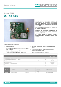
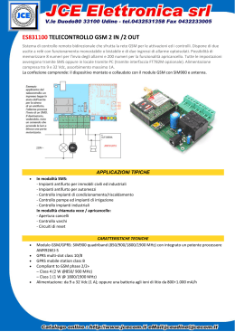
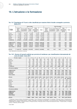
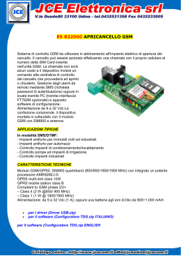
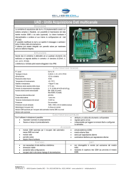
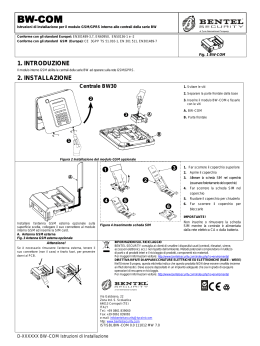
CELIND
®
CELIND
®
Manuale tecnico
di installazione
Technical
installation manual
GSM
TERMINALE GSM PER LA TRASMISSIONE,
RICEZIONE ED ELABORAZIONE DI COMANDI,
MISURE ED ALLARMI.
GSM TERMINAL FOR TRANSMISSION,
RECEPTION AND ELABORATION OF
COMMANDS, MEASURES AND ALARMS.
CELIND MANUALE TECNICO DI INSTALLAZIONE
INDICE SEZIONE ITALIANO
1 Premessa
1.1
1.2
1.3
1.4
1.5
1.6
1.7
1.7.1
1.7.2
COPYRIGHT
EDIZIONE DEL MANUALE
TRADEMARKS
DICHIARAZIONE DI CONFORMITÀ
GARANZIA
AGGIORNAMENTI
PROCEDURA DI RESO PER RIPARAZIONE (RMA)
Confezione e spedizione dei prodotti non conformi
Allegato RMA
5
5
5
5
6
6
7
7
8
2 Generalità
2.1
2.1.1
2.2
2.3
2.3.1
2.3.2
2.3.3
2.3.4
2.3.5
CONTENUTO DELLA CONFEZIONE DI VENDITA
Versioni previste
APPLICAZIONI
CARATTERISTICHE TECNICHE
Descrizione fisica
Connessioni esterne
Caratteristiche principali
Prestazioni del CELIND GSM
Aspetti elettrici
9
9
9
10
10
10
10
11
11
3 Introduzione
• Questo documento è di proprietà di AUDIOTEL ENGINEERING S.p.A. e non può essere copiato o fatto circolare
senza esplicito permesso scritto
• This document is AUDIOTEL ENGINEERING S.p.A. property. Not part of this pubblication may be reproduced or circulated
without the publisher’s prior consent in writing.
Cod. 0808P1Q1000E2
3.1
3.2
3.2.1
3.3
3.3.1
3.3.2
3.3.3
3.3.4
3.3.5
3.3.6
3.3.7
3.3.8
3.4
3.4.1
3.4.2
AVVERTENZE
DESCRIZIONE MODULO CELIND
Funzionalità
INSTALLAZIONE
Fissaggio di CELIND
Connettori interni
Collegamento cavo di alimentazione
Collegamento cavi di connesione I/O
Connessione V.24-RS-232C per cavo seriale
Attacco d’antenna
Inserimento SIM CARD
Attivazione
OROLOGIO INTERNO
Sostituzione batteria
Verifica attivazione orologio
12
13
13
15
15
16
17
18
20
21
22
23
24
24
25
Ultima revisione - Last Update: 09/2002
© AUDIOTEL Engineering S.p.A.
3
CELIND TECHNICAL INSTALLATION MANUAL
TABLE OF CONTENTS (ENGLISH SECTION)
COPYRIGHT
MANUAL EDITION
TRADEMARKS
CONFORMITY DECLARATION
GUARANTEE
UPDATING
RETURN OF GOODS FOR REPAIR PROCEDURE (RMA)
Packing and dispatch of nonconforming products
RMA Appendix
I TA L I A N O
1 Premessa
Nel ringraziarVi per la preferenza accordataci Vi preghiamo di leggere attentamente questo
manuale, per utilizzare al meglio l’apparato CELIND.
1 Preliminary Notes
1.1
1.2
1.3
1.4
1.5
1.6
1.7
1.7.1
1.7.2
CELIND MANUALE TECNICO DI INSTALLAZIONE
27
27
27
27
28
28
29
1.1 COPYRIGHT
AUDIOTEL Engineering S.p.A. Tutti i diritti riservati.
La riproduzione, l’adattamento o la trascrizione di questo documento senza preventiva autorizzazione scritta sono proibiti, tranne nei casi previsti dalle leggi relative al copyright.
Copyright© 1998
29
30
1.2 EDIZIONE DEL MANUALE
Prima Edizione: Giugno 2001
31
1.3 TRADEMARKS
CELIND è un marchio AUDIOTEL Engineering S.p.A.
2 General Notes
2.1
2.1.1
2.2
2.3
2.3.1
2.3.2
2.3.3
2.3.4
2.3.5
SALES PACK CONTENTS
Available versions
APPLICATIONS
TECHNICAL DETAILS
Physical description
External connections
Main features
CELIND GSM performance
Electrical aspects
31
31
32
32
32
32
33
4
IMPORTANT INFORMATION
CELIND MODULE DESCRIPTION
Functions
INSTALLATION
How to fasten CELIND onto the wall
Internal connectors
Connecting the power supply cable
Connecting the I/O connection cables
V.24-RS-232C connection for the serial cable
Aerial connector
SIM-CARD insertion
Actuation
INTERNAL CLOCK
Battery replacement
Clock actuation check
Dichiara sotto la propria responsabilità che il prodotto:
33
3 Introduction
3.1
3.2
3.2.1
3.3
3.3.1
3.3.2
3.3.3
3.3.4
3.3.5
3.3.6
3.3.7
3.3.8
3.4
3.4.1
3.4.2
1.4 DICHIARAZIONE DI CONFORMITÀ
AUDIOTEL Engineering S.p.A.
Via del Chioso, 6 - 24030 Mozzo (BG) Italia
34
35
35
37
CELIND codice 0802P1Q3000E1
è conforme con le normative vigenti in relazione alla direttiva R&TTE 99/5/CE ed in particolare alle seguenti norme:.
Health and Safety
EMC
RF spectrum efficency
37
38
39
40
43
44
46
46
EN60950
ETS 300342-1
3GPP TS 51.010-1, v4.0.2
(GSM 11.10-1),
Draft ETSI EN 301 511, v7.0.0
(GSM 13.11)
0681
42
45
(Art. 3.1 a):
(Art. 3.1 b):
(Art. 3.2):
Settembre 2002
Luigi Caroli
Direttore Tecnico
Settembre 2002
Fabio Rossmann
Responsabile Assicurazione Qualità
47
© AUDIOTEL Engineering S.p.A.
© AUDIOTEL Engineering S.p.A.
5
I TA L I A N O
1.5 GARANZIA
Questo prodotto è garantito contro eventuali difetti dei materiali e della lavorazione per un
periodo di 12 mesi dalla data di spedizione.
La garanzia non copre difetti dovuti a:
• Uso improprio ed incuria
• Danni provocati da agenti atmosferici
• Atti vandalici
• Materiale soggetto ad usura.
AUDIOTEL si riserva, a sua esclusiva discrezione il diritto di riparare o sostituire i prodotti
ritenuti difettosi.
La garanzia si considera decaduta quando il guasto è indotto da un uso improprio o da una
procedura operativa non contemplata in questo manuale.
CELIND MANUALE TECNICO DI INSTALLAZIONE
1.7 PROCEDURA DI RESO PER RIPARAZIONE (RMA)
AUDIOTEL accetta resi solo se preventivamente autorizzati.
Nel caso di acquisto effettuato direttamente presso AUDIOTEL, l’autorizzazione al rientro
per riparazione deve essere richiesta ad AUDIOTEL stessa, via Fax al numero 035.614000,
tramite apposito modulo allegato.
In alternativa, l’acquirente deve richiedere assistenza presso il punto vendita dove ha
acquistato il prodotto.
In entrambe le situazioni occorre fornire le seguenti informazioni:
I TA L I A N O
CELIND MANUALE TECNICO DI INSTALLAZIONE
• Identificazione anagrafica dell’acquirente o, nel caso di società, almeno il nome di una
persona di riferimento
• Numero di serie del prodotto
• Configurazione d’utilizzo al momento del guasto.
1.6 AGGIORNAMENTI
Il sito AUDIOTEL è mantenuto continuamente aggiornato con informazioni di tipo commerciale e tecnico.
In particolare sono disponibili:
• Presentazione del portafoglio prodotti
• Annunci commerciali
• Revisioni dei manuali operativi
• Note applicative
• Aggiornamenti software
• Informazioni per la corretta installazione e manutenzione dei prodotti
• Indirizzi utili
Il laboratorio riparazioni di AUDIOTEL, contattato dal punto vendita o dal cliente finale (solo
in caso di vendita diretta) rilascerà un numero di RMA che dovrà essere riportato, a cura
del punto vendita/cliente, sull’imballo e sul Documento di Trasporto (DDT).
ATTENZIONE: Se il numero di RMA non è presente sull’imballo esterno il magazzino è autorizzato a respingere la merce a spese del mittente.
Il materiale contraddistinto da numero di RMA dev’essere spedito entro 15 giorni lavorativi
dalla assegnazione del RMA stesso, in porto franco, al seguente indirizzo:
Att.ne UFFICIO RIPARAZIONI
AUDIOTEL Engineering S.p.A.
Via del Chioso, 6
24030 MOZZO (BG)
1.7.1 Confezione e spedizione dei prodotti non conformi
Nella confezione, oltre al prodotto non conforme, si richiede di includere:
• Una descrizione dettagliata del difetto riscontrato
• Copia della fattura d’acquisto o numero della fattura.
La spedizione di reso da riparazione è in PORTO ASSEGNATO.
Per prodotti NON IN GARANZIA il cliente può richiedere un preventivo di spesa.
Se un apparato NON È IN GARANZIA ed alla verifica del ns. personale tecnico risulta
correttamente funzionante, verrà in ogni caso addebitato al cliente un importo pari a 40 EURO
(L. 77.451) + I.V.A.
www.audiotel.it
6
© AUDIOTEL Engineering S.p.A.
© AUDIOTEL Engineering S.p.A.
7
CELIND MANUALE TECNICO DI INSTALLAZIONE
2.1 CONTENUTO DELLA CONFEZIONE DI VENDITA
• Manuale tecnico di installazione (il presente manuale)
• Apparato CELIND (Unità centrale + I/O Expander)
• Cavo di alimentazione
• Cavo di interconnessione I/O
RICHIESTA NUMERO DI RMA
PER RIENTRO MERCE IN RIPARAZIONE
Data di compilazione:
Società:
Persona di riferimento:
2.1.1 Versioni previste
L’apparato CELIND viene venduto nella seguente versione:
Tel.:
Fax:
Descrizione apparecchiatura:
I TA L I A N O
2 Generalità
1.7.2 Allegato RMA
I TA L I A N O
CELIND MANUALE TECNICO DI INSTALLAZIONE
Dettagliata descrizione dei malfunzionamenti:
- CELIND I/O
(gestione I/O, trasmissione dati)
2.2 APPLICAZIONI
• Building automation
• Telecontrolli industriali
• Trasmissione allarmi
• Controlli ambientali
• Telecomandi in postazioni remote
• Telemetria
• Sicurezza
Numero di serie:
Descrizione degli eventuali accessori resi:
Numero e data Fattura di acquisto o Documento di Trasporto (DDT):
(Se questo campo non viene compilato, la merce verrà considerata fuori garanzia)
Richiesta di preventivo:
Si:
No:
Per la merce resa, fuori garanzia, che risulterà funzionante verrà in ogni caso, addebitato un
importo di 40 EURO (L. 77.451) + I.V.A. a forfait per controllo e ricollaudo.
Spazio riservato per la risposta di AUDIOTEL:
R.M.A. N.
Il numero di RMA è da riportare sull’imballo esterno e sul Documento di Trasporto (DDT):
se non presente il magazzino AUDIOTEL è autorizzato a respingere la merce.
8
© AUDIOTEL Engineering S.p.A.
© AUDIOTEL Engineering S.p.A.
9
CELIND MANUALE TECNICO DI INSTALLAZIONE
2.3.4 Prestazioni del CELIND GSM
2.3.1 Descrizione fisica
2.3.1.1 Unità Centrale
DIMENSIONI
PESO
TEMPERATURA DI FUNZIONAMENTO
UMIDITÀ RELATIVA
GRADO DI PROTEZIONE
CONTENITORE
GSM fase 2
185 mm (altezza) x 70 mm (larghezza) x 93 mm (profondità)
380g (compreso modulo GSM)
Da –20°C a +55°C
Da 0 a 90% non condensata
IP 21
IP 54
DIMENSIONI
PESO
Prestazioni/Servizi
900MHz
1800MHz
Interfaccia
Gestione da DTE
SMS
2.3.1.2 I/O Expander
90 mm (altezza) x 160 mm (larghezza) x 60 mm (profondità)
300 gr
2.3.2 Connessioni esterne
2.3.2.1 Unità Centrale
CONNETTORE DB9 FEMMINA
CONNETTORE PLUG-IN
CONNETTORE ANTENNA
CONNETTORI I/O
Dati
Interfaccia V.24 con livello RS-232
Ingresso alimentazione in continua
Tipo SMA femmina (Integrata nel CELIND)
N° 2 MICRO-FIT maschio (2 file x 8 contatti)
2.3.2.2 I/O Expander
CONNETTORI I/O
N° 6 morsettiere passo 5.08 (totale di 54 contatti)
2.3.3 Caratteristiche principali
ALIMENTAZIONE PRIMARIA
CONSUMI MEDI
MICROPROCESSORE
MEMORIA NON VOLATILE
OROLOGIO
TRASMETTITORE
PORTA DI COMUNICAZIONE SERIALE
INTERFACCIA BF
INPUT DIGITALI OPTOISOLATI (5..50V)
OUTPUT DIGITALI SU RELAIS
(max 2A 30Vdc - 0,6A 110Vdc - 0,6A 125Vac)
INPUT ANALOGICI
(0..10V o 0..20mA con risoluzione a 8 bit)
OUTPUT ANALOGICO (0...5V)
10
Fax
Voce (Audio)
Tensione continua da 8 a 28 Vcc
Operativo: ~ 140 mA a 12 Vcc
Stand-by : ~ 80 mA a 12 Vcc
16 Bit
2 Mbyte
(RTC) Interno
GSM Dual Band
N° 1 V24-RS232
N° 1 Per trasmissioni in fonia
N° 8
N° 8
I TA L I A N O
I TA L I A N O
2.3 CARATTERISTICHE TECNICHE
CELIND MANUALE TECNICO DI INSTALLAZIONE
Dettagli
Classe 4 (2W)
Classe 1 (1W)
Porta seriale V.24/V.28 RS_232C
V.25ter
Modalità
Comandi AT
GSM 07.05
GSM 07.07
Invio
Mobile Originated (MO)
Ricezione
Mobile Terninated (MT)
Text & PDU (punto a punto)
Modalità
Cell broadcast (punto _ multipunto)
Teleservice
TS22, TS21
Standard comandi AT GSM 07.05
2400 bps
V22bis
4800 bps
V32
9600 bps
V32
Velocità
2400 bps
V110
4800 bps
V110
9600 bps
V100
Trasparente
Profilo
Non trasparente (RLP)
Controllo flusso
Nessuno o RTS/CTS
Bearer service
BS24, BS25, BS26
Velocità
2400, 4800, 7200 e 9600 bits/s
GSM TS62
Profilo
Modalità trasparente
Compatibilità
Classe 1 – Gruppo 3
CCITT Rec.
CCITT T.30, T.4
Servizio disponibile ma non gestito (non è richiesto)
2.3.5 Aspetti elettrici
Parametri
Tensione di alimentazione
Corrente di picco
Corrente media in TX
Corrente media in RX
Alimentazione SIM
Stand-by
N° 4
N° 1
© AUDIOTEL Engineering S.p.A.
© AUDIOTEL Engineering S.p.A.
Min.
10
GSM 900
Typ.
12
Max
16
2,5
510
60
3o5
Min.
10
GSM 1800
Typ.
12
Max.
16
1
260
65
3o5
50
50
Unità
V cc
A
mA
mA
V
mA
11
3 Introduzione
3.1 AVVERTENZE
Per un funzionamento sicuro ed efficace del prodotto, si raccomanda di leggere attentamente le seguenti istruzioni prima dell’utilizzo.
Il prodotto può essere impiegato esclusivamente per l’uso per il quale è stato concepito e
costruito. Qualsiasi altra forma di impiego è da considerarsi a totale responsabilità dell’utilizzatore.
L’installazione, programmazione e messa in funzione è consentita solamente ad operatori
abilitati; detti operatori devono essere persone fisicamente ed intellettualmente idonee.
La messa in funzione, deve essere eseguita solamente dopo una corretta installazione, pertanto l’utilizzatore deve provvedere ad effettuare con cura tutte le operazioni descritte nei
manuali in dotazione.
“AUDIOTEL” non si riterrà responsabile di inconvenienti, rotture, incidenti, ecc. dovuti alla
non conoscenza o alla mancata applicazione delle prescrizioni indicate.
Lo stesso dicasi per eventuali modifiche non autorizzate.
“AUDIOTEL” si riserva il diritto di modificare il prodotto, per qualsiasi esigenza di carattere
costruttivo o commerciale, senza l’obbligo di aggiornare tempestivamente i manuali di riferimento.
L’apparato “CELIND” utilizza lo standard GSM per la telefonia cellulare; non può essere quindi impiegato in zone che si trovano al di fuori dell’area di copertura del sistema stesso.
Dato che il sistema GSM è una tecnologia a radiofrequenza (RF), vi possono essere interferenze in presenza di altri apparecchi telefonici o problemi nel funzionamento di dispositivi
elettronici insufficientemente protetti dall’energia a radiofrequenza.
È vietato l’uso del “CELIND”:
• In aereo
• In ospedali e centri di cura
• Nelle vicinanze di distributori di carburante o dove sia presente un pericolo di esplosione.
• Nei siti dove si opera con agenti chimici in genere, e con particolare attenzione alle norme
di sicurezza per ambienti saturi (o potenzialmente saturi) di gas o esalazioni volatili.
• In luoghi dove siano in corso operazioni di detonazione.
• Nei pressi di apparati elettromedicali, compresi sistemi di ausilio personali come:
pacemakers e apparecchi elettroacusici (hearing aids).
Il prodotto è comunque conforme agli standard di sicurezza per quanto riguarda l’esposizione all’energia a radiofrequenza.
CELIND MANUALE TECNICO DI INSTALLAZIONE
3.2 DESCRIZIONE MODULO CELIND
CELIND è un prodotto che permette il controllo, telelettura, telemetria e trasmissione di allarmi, gestiti in maniera completamente automatica, su rete GSM.
È composto da una unità centrale contenente la parte radio GSM e la scheda micro (per la
gestione delle funzionalità previste) e dall’I/O Expander contenente la scheda I/O.
I TA L I A N O
I TA L I A N O
CELIND MANUALE TECNICO DI INSTALLAZIONE
Scheda micro
di gestione
Parte radio GSM
Scheda I / O
Grazie ad un semplice software con menù guidato a finestre è possibile configurare e gestire eventi sugli I/O. Permette inoltre la verifica del segnale RF gsm, la programmazione da
locale o remoto sia del software di configurazione che degli eventuali aggiornamenti del
firmware. Si tratta perciò di una apparecchiatura gestibile completamente da remoto.
3.2.1 Funzionalità
L’apparato CELIND è costituito sostanzialmente da due blocchi funzionali hardware:
• Una unità di controllo a microprocessore (CPU) equipaggiata con:
- 1 Mbytes ram (dati e programma)
- 1 + 1 Mbytes di memoria flash (dati e programma)
- 2 Kbytes di memoria EEPROM (dati )
- Interfaccia seriale standard V24
- Una interfaccia di input/output verso l’esterno (I/O Expander).
• Una unità di commutazione delle seriali (ROUTER) che rende possibili le seguenti
connessioni:
- DTE <> GSM (con la CPU isolata oppure in monitor su TXD o RXD)
- DTE <> CPU
- CPU <> GSM
(Quando una unità viene isolata i livelli elettrici dei segnali della sua interfaccia seriale sono
tenuti nello stato non attivo: RTS/CTS non attivi e RXD/TXD attivi.)
12
© AUDIOTEL Engineering S.p.A.
© AUDIOTEL Engineering S.p.A.
13
CELIND MANUALE TECNICO DI INSTALLAZIONE
30
I TA L I A N O
3.3 INSTALLAZIONE
3.3.1 Fissaggio di CELIND
Per il fissaggio dell’unità centrale è disponibile una staffa di sostegno dotata di due fori
opportunamente sagomati con interasse 30mm, adatti sia al montaggio all’interno di un box
plastico che per il fissaggio a parete. Per quanto riguarda il fissaggio dell’ I/O Expander, è
stato previsto un contenitore plastico tale da poter essere alloggiato su di una guida DIN.
ESEMPIO DI TRASMISSIONE DATI
I TA L I A N O
CELIND MANUALE TECNICO DI INSTALLAZIONE
mm
Si utilizzano, per fissare il CELIND all’interno di un box plastico, due viti M4 con testa cilindrica ø 7x3 presenti nel contenitore stesso.
Una volta allentate, si pone CELIND in modo che i fori sulla staffa entrino nella testa delle viti.
Poi si sposta verso il basso CELIND, fino a inserire il gambo delle viti nelle feritoie sopra i fori.
A questo punto basta avvitare portando la testa delle viti in battuta sulla staffa.
Per il fissaggio a parete le due viti devono essere invece predisposte utilizzando dei tasselli ad espansione. Si ricorda che le due viti di fissaggio devono essere poste ad un interasse di 30mm. Un’alternativa al sistema precedentemente descritto è data dai due fori posti in
verticale sulla staffa di sostegno.
In questo caso l’interasse è di 45 mm e le viti M4 da utilizzare devono essere a testa svasata.
ESEMPIO DI GESTIONE I/O
45 mm
14
© AUDIOTEL Engineering S.p.A.
© AUDIOTEL Engineering S.p.A.
15
I TA L I A N O
3.3.2 Connettori interni
Si accede ai connettori interni di alimentazione, di connessione I/O, di connessione cavo
seriale, all’attacco dell’antenna e al SIM-READER dal lato inferiore del CELIND, togliendo la
copertura fissata con 3 viti a croce.
CELIND MANUALE TECNICO DI INSTALLAZIONE
3.3.3 Collegamento cavo di alimentazione
• Inserire il connettore del cavo in dotazione nel connettore di alimentazione presente
sul CELIND.
• Infilare il cavo di alimentazione nel passacavo centrale della copertura.
I TA L I A N O
CELIND MANUALE TECNICO DI INSTALLAZIONE
Connettore
cavo seriale
Alimentazione
Attacco antenna
Copertura
Sim-reader
Connettori
J3
I/O
J4
Caratteristiche cavo di alimentazione
Parametro
Cavo
Materiale
AWG
Lunghezza
Intestazione
Colori
Lato CELIND
Lato Alimentatore
Polo positivo
Gnd
Dettaglio
bipolare
Rame
24
2mt
Connettore Molex Micro-Fit 3.0
Cavo
Rosso
Nero
Portafusibile
N.2 Cavetti Rosso/Nero
Molex Micro-Fit
4p. M. Vol.
Contatti Femm.
16
© AUDIOTEL Engineering S.p.A.
© AUDIOTEL Engineering S.p.A.
17
I TA L I A N O
3.3.4 Collegamento cavi di connessione I/O
• Inserire il cavo di connessione I/O nel connettore (J3) posto a sinistra sul lato frontale di
CELIND (vedere figura). ATTENZIONE: non collegare il cavo di connessione I/O al connettore J4 (tale connettore è riservato per usi futuri). Togliere dal lato esterno i passacavi inferiori, presenti sulla copertura, e infilare i cavi di connessione I/O.
CELIND MANUALE TECNICO DI INSTALLAZIONE
Schema morsettiera I/O Expander
• Di seguito si riporta lo schema delle corrispondenze tra i segnali elettrici e i morsetti presenti sull’unità I/O Expander.
Ingressi
Analogici
I TA L I A N O
CELIND MANUALE TECNICO DI INSTALLAZIONE
Ingressi
Digitali
J3
• Serrare i passacavi
• Collegare i fili in uscita dai cavetti agli opportuni morsetti posizionati sull’I/O Expander.
• Per il collegamento dei segnali I2C bus fare riferimento alla tabella seguente:
Connettore Molex 16p. Fem. (pin)
7
8
15
16
Segnali I2C bus
LCL
LDA
GND
GND
Alimentazione I2C Bus
Esterna Extender
• Per il collegamento dei segnali di fonia (occorre munirsi di una cornetta) fare riferimento
alla tabella seguente:
Connettore Molex 16p. Fem. (pin)
1
2
9
10
5
13,14,15,16
Segnali fonia
Speaker (Pos.)
Speaker (Neg.)
Micro (Pos.)
Micro (Neg.)
Vcc
GND
Uscita
Analogica
TIPO
SEGNALE
INGRESSI
ANALOGICI
INGRESSI
DIGITALI
In caso di non utilizzo dei segnali di fonia si suggerisce di isolare i rispettivi contatti del cavo di I/O
Caratteristiche cavo di connessione I/O
USCITA
ANALOGICA
1 = CAVO FONIA
Ferrite
2 = CAVO SEGNALI
All’atto dell’installazione del prodotto, il cavo di connessione I/O può essere
accorciato, ma non allungato e solo dopo l’installazione inserire su entrambe
le estremità del cavo segnali le due ferriti antidisturbo in dotazione
18
USCITE
SU RELAIS
Ferrite
Molex Micro-Fit 2x8p. F.V.Crimp.
Code 43025 – 1600
Contatti Femmina
Vista frontale del connettore
© AUDIOTEL Engineering S.p.A.
Ingressi
Digitali
Uscite su
Relais
I C BUS
EXTENDER
2
NOME
SEGNALE
I_A0
I_A1
I_A2
I_A3
I_D0
I_D1
I_D2
I_D3
I_D4
I_D5
I_D6
I_D7
Vmax
(V)
Imax
(mA)
0..10
0..20
O_A0
0..5
O_D0
O_D1
O_D2
O_D3
O_D4
O_D5
O_D6
O_D7
LDA
ALIMENTAZIONE
ESTERNA
© AUDIOTEL Engineering S.p.A.
5..50
30 Vdc
110Vdc
125Vac
Ingresso in tensione
Ingresso in corrente
Massa
+
Ingresso positivo
-
Ingresso negativo
3
5
O_A0
2000
600
600
Uscita analogica
Contatto relais normalmente aperto
Nc.
Contatto relais normalmente chiuso
Nc.a.
Contatto relais normalmente aperto/chiuso
(selezionabile con ponticelli hardware)
C.
8..28
Descrizione
=
Na.
LCL
Vcc
Simboli riportati
sul morsetto
V
I
Lda
Lcl
Gnd
Vcc +
Vcc -
Comune
Segnali dell’ I2C BUS
Positivo alimentazione
Negativo alimentazione
19
I TA L I A N O
Un’osservazione particolare meritano le uscite su relais: le uscite indicate come O_D0…O_D3 presentano, a livello di
morsettiera, sia un’uscita N.A. (normalmente aperto) che N.C. (normalmente chiuso). Le uscite indicate come
O_D4…O_D7 presentano, sempre a livello di morsettiera, una sola uscita configurabile N.A. oppure N.C. tramite i ponticelli presenti sulla scheda (vedere figura sotto).
CELIND MANUALE TECNICO DI INSTALLAZIONE
3.3.6 Attacco d’antenna
Sempre nella parte inferiore del CELIND è presente un connettore RF di tipo SMA femmina
normalmente connesso all’antenna interna.
Accertarsi che il connettore d’antenna sia ben serrato.
I TA L I A N O
CELIND MANUALE TECNICO DI INSTALLAZIONE
Connettore
antenna
Caratteristiche tecniche antenna interna
3.3.5 Connessione V.24-RS_232C per cavo seriale
Nella parte inferiore della struttura del CELIND è presente un connettore di tipo ISO DIN
41652 (DB9 femmina).
I segnali presenti su questo connettore consentono di interconnettere, tramite un cavo
seriale in modalità V.24/V.28 RS_232C, CELIND con un DTE esterno.
Nella tabella che segue sono indicati i nomi e le funzioni dei segnali correlati con la posizione sul connettore DB9.
Pin
1
2
3
4
5
6
7
8
9
EIA
DCD
RX
TX
DTR
GND
DSR
RTS
CTS
RI
CCITT
C109
C104
C103
C108
C102
C107
C105
C106
C125
Uso
Data Carrier Detect
Receiver Data
Transmit Data
Data Terminal Ready
Ground
Data Set Ready
Request To Send
Clear To Send
Ring Indicator
IN/OUT
Out
Out
In
In
Ground
Out
In
Out
Out
Nota: Qualora si debba prevedere la connessione verso un DTE esterno in remoto, non collegare sulla porta seriale del DTE, il DTR (Data Terminal Ready) Pin 4 della RS_232C.
Caratteristiche
Dual-Band GSM
890-960MHz
1710-1880MHz
50 Ω
± 1:1,5
Omnidirezionale
25Wmax (picco) @ 55°C
Circolare @ ± 0,5dB
± 35° @ 3dB
SMA (maschio)
Antenna esterna
In determinate condizioni operative l’antenna interna non consente un’ottimale ricezione
del segnale RF, per questo motivo l’apparato CELIND è predisposto per operare anche con
un’antenna esterna di tipo direttivo.
In tal caso staccare il connettore dell’antenna interna e connettere quello dell’antenna
esterna, facendo passare il relativo cavo attraverso il passacavo utilizzato per l’alimentazione.
Attenzione!
• Non tenere l’antenna con le mani quando l’apparato è in uso. Ciò penalizza la qualità del
collegamento, oltre a richiedere al CELIND un aumento della potenza in trasmissione.
54321
• Non utilizzare il CELIND se l’antenna è visivamente danneggiata, in tal caso la sostituzione
dev’essere eseguita senza indugio. Utilizzare esclusivamente le antenne prescritte da
AUDIOTEL Engineering S.p.A.
9876
20
Parametro
Profilo
Banda 900MHz
Banda 1800MHz
Impedenza
WSVR
Tipologia
Potenza
Diagramma di irradiazione sul piano
orizzontale
Diagramma di irradiazione sul piano verticale
Connettore
© AUDIOTEL Engineering S.p.A.
© AUDIOTEL Engineering S.p.A.
21
I TA L I A N O
3.3.7 Inserimento SIM-CARD
Il SIM-READER si trova posizionato nella parte inferiore del CELIND.
Premere il pulsantino di estrazione SIM-CARD, aiutandosi con una punta, in modo da
togliere il supporto PORTA-SIM.
Alloggiare la SIM-CARD nel supporto e inserirlo nel modulo GSM assicurandosi che i contatti della SIM-CARD guardino verso il basso.
CELIND MANUALE TECNICO DI INSTALLAZIONE
3.3.8 Attivazione
Effettuati tutti i collegamenti e inserita la SIM-CARD,
rimontare la copertura di accesso ai connettori
interni; quindi inserire in CELIND in modo che la guida
presente sulla parte posteriore si infili sulla staffa di
sostegno.
I TA L I A N O
CELIND MANUALE TECNICO DI INSTALLAZIONE
Accensione (on/off)
Il modulo CELIND non dispone di un interruttore,
l’accensione e lo spegnimento sono gestiti connettendo (power_on) e rimuovendo (power_off) il cavo
di alimentazione ad un alimentatore 12 Vcc.
Contatti
Segnalazioni visive (led)
Sul lato frontale della copertura sono visibili due leds di segnalazione che dinamicamente
presentano le condizioni operative di CELIND: la condizione dei due leds deve essere verificata contemporaneamente.
Contatti
Attenzione!
Dovendo sostituire la SIM-CARD, con CELIND già in uso, è necessario dapprima scollegare
il cavo di alimentazione. Ricollegare il cavo ad operazione ultimata.
22
© AUDIOTEL Engineering S.p.A.
Led verde
Led rosso
Condizione CELIND
Spento
Lampeggio molto veloce
Lampeggio lento
Lampeggio lento
Lampeggio molto veloce
Lampeggio lento
Lampeggio lento
Spento
Lampeggio molto veloce
Lampeggio molto veloce
Lampeggio lento
Lampeggio molto veloce
Acceso a luce fissa
Lampeggio veloce
Non alimentato
Inizializzazione (circa 20 secondi)
Nessun programma utente caricato
Funzionamento corretto
Nessuna SIM inserita (Lamp. continuo)
No presenza rete GSM (Verific. antenna)
Apparato in Tx o Rx con Link attivo
© AUDIOTEL Engineering S.p.A.
23
I TA L I A N O
3.4 OROLOGIO INTERNO
La batteria al litio interna ha una funzione di back-up.
Quando tutto il sistema è collegato ad una alimentazione primaria, la batteria non è
utilizzata; in caso di assenza alimentazione, provvederà a mantenere inalterate le funzioni
del clock interno.
CELIND MANUALE TECNICO DI INSTALLAZIONE
3.4.2 Verifica attivazione orologio
Nel caso l’orario non risultasse impostato correttamente, controllare sulla scheda I/O, che
il Jumper “JP1” sia in corto circuito. Impostare l’ora tramite comandi “AT dedicati”, poi spegnere e riaccendere CELIND.
Attenzione ! La batteria ha una durata di circa 4 anni.
I TA L I A N O
CELIND MANUALE TECNICO DI INSTALLAZIONE
JP1
3.4.1 Sostituzione batteria
Per la sostituzione della batteria dell’orologio è necessario procedere nel seguente modo:
• Togliere la copertura inferiore dell’I/O Expander facendo leva sulle 4 linguette di plastica
• Estrarre la scheda dal contenitore e sostituire la batteria
• Rimontare il tutto ripercorrendo a ritroso i passi fin qui seguiti
Attenzione !
La batteria dell’orologio è saldata a stagno sulla scheda I/O. Non disponendo di un laboratorio attrezzato per la saldatura, rivolgersi ad AUDIOTEL Engineering S.p.A.
Batteria
24
© AUDIOTEL Engineering S.p.A.
© AUDIOTEL Engineering S.p.A.
25
CELIND MANUALE TECNICO DI INSTALLAZIONE
CELIND TECHNICAL INSTALLATION MANUAL
1 Preliminary Notes
We thank you for having chosen us and ask you to read this manual carefully, for the best
use of the CELIND appliance.
ENGLISH
1.1 COPYRIGHT
AUDIOTEL Engineering S.p.A. All rights reserved.
Reproduction, adaptation or transcription of this document without prior authorisation in
writing are prohibited, except in cases provided for by the relative copyright laws.
Copyright© 1998
1.2 MANUAL EDITION
First Edition: June 2001
1.3 TRADEMARKS
CELIND is an AUDIOTEL Engineering S.p.A. trademark.
1.4 CONFORMITY DECLARATION
We, AUDIOTEL Engineering S.p.A.
Of Via del Chioso, 6 - 24030 Mozzo (BG) Italy
Declare under our sole responsibility that the product
CELIND code 0802P1Q3000E1
Complies with the regulations in force, with reference to the R&TTE 99/5/CE directive and,
above all, with the following standards:
Health and Safety
EMC
RF spectrum efficency
(Art. 3.1 a):
(Art. 3.1 b):
(Art. 3.2):
EN60950
ETS 300342-1
3GPP TS 51.010-1, v4.0.2
(GSM 11.10-1),
Draft ETSI EN 301 511, v7.0.0
(GSM 13.11)
0681
Date: September 2002
Luigi Caroli
Head of Development
26
© AUDIOTEL Engineering S.p.A.
© AUDIOTEL Engineering S.p.A.
Date: September 2002
Fabio Rossmann
Head of Quality Assurance
27
ENGLISH
1.5 GUARANTEE
This product is guaranteed against possible material and manufacturing defects for a period of 12 months from the dispatch date.
The guarantee does not cover defects due to:
• Improper use and carelessness
• Damage caused by atmospheric agents
• Acts of vandalism
• Material subject to wear.
AUDIOTEL, at its exclusive discretion, reserves the right to repair or replace products considered defective.
The guarantee will be considered lapsed when the fault is induced by improper use or by
an operating procedure not contemplated in this manual.
1.6 UPDATES
The AUDIOTEL site is continually updated with commercial and technical information.
The following are available in particular:
• Products portfolio presentation
• Commercial information
• Operating manual revisions
• Application notes
• Software updates
• Information for correct product installation and maintenance
• Useful addresses
CELIND TECHNICAL INSTALLATION MANUAL
1.7 RETURN OF GOODS FOR REPAIR PROCEDURE (RMA)
AUDIOTEL only accepts returns that have been previously authorised.
In the case of a purchase made directly from AUDIOTEL, AUDIOTEL itself must be asked for
authorisation of a return for repair, via Fax at number (+39) 035.614000, using the attached
form.
Alternatively the purchaser must ask for assistance at the point of sale from which the product was bought.
The following information must be supplied in both cases:
• Full name and address of the purchaser or, in the case of a company, at least the name of
a person to contact
• Product serial number
• Usage configuration at the time of the fault.
The AUDIOTEL repair laboratory, contacted by the point of sale or the end client (only in the
case of a direct sale), will issue an RMA number which the point of sale/client must quote
on the packing and the Transport Document (DDT).
N.B.: If the RMA number is not present on the outer pack, the warehouse is authorised to
reject the goods at the expense of the sender.
The material marked with the RMA number must be sent, carriage free, to the following
address within 15 working days of assignment of the RMA itself:
ENGLISH
CELIND TECHNICAL INSTALLATION MANUAL
REPAIR OFFICE
AUDIOTEL Engineering S.p.A.
Via del Chioso, 6
24030 MOZZO (BG)
1.7.1 Packing and dispatch of nonconforming products
The following must be included in the pack as well as the nonconforming product:
• A detailed description of the defect detected
• A copy of the purchase invoice or the invoice number.
Dispatch of a return for repair is CARRIAGE FORWARD.
The client can ask for a cost estimate for products OUT OF GUARANTEE.
If an appliance is OUT OF GUARANTEE and proves to be operating correctly when checked
by our technical personnel the client will, in any case, be charged a sum of 40 EURO
(77,451 LIRE) + VAT.
www.audiotel.it
28
© AUDIOTEL Engineering S.p.A.
© AUDIOTEL Engineering S.p.A.
29
CELIND TECHNICAL INSTALLATION MANUAL
2 General Notes
1.7.2 RMA Appendix
Date:
Company:
Person to contact:
2.1.1 Available versions
The CELIND appliance is sold in the following versions:
Tel.:
Fax:
Description of equipment:
ENGLISH
2.1 SALES PACK CONTENTS
• Technical installation manual (this manual)
• CELIND appliance (Central unit + I/O Expander)
• Power supply cable
• I/O interconnection cable
RMA NUMBER REQUEST
FOR RETURN OF GOODS FOR REPAIR
ENGLISH
CELIND TECHNICAL INSTALLATION MANUAL
Detailed description of faults:
- CELIND I/O
(I/O management, data transmission)
2.2 APPLICATIONS
• Building automation
• Industrial remote control
• Alarm transmission
• Environmental controls
• Telecontrol from remote stations
• Telemetry
• Security
Serial number:
Description of any returned accessories:
Purchasing Invoice number and date or Transport Document (DDT):
(If this box is not filled in, the goods will be considered out of guarantee)
Request for quotation:
Yes:
No:
For returned goods out of guarantee, which will prove to be operating correctly, the client will,
in any case, be charged a sum of 40 EURO (77,451 Lire) + VAT for checks and retesting.
Reserved space for the response of AUDIOTEL:
R.M.A. No.
The RMA number must be shown on the outer packaging and on the transport document
(DDT). If it is not present, the AUDIOTEL warehouse is authorised to send back the goods.
30
© AUDIOTEL Engineering S.p.A.
© AUDIOTEL Engineering S.p.A.
31
2.3 TECHNICAL DETAILS
2.3.4 CELIND GSM performance
2.3.1 Physical description
Performance/Services
900MHz
GSM phase 2
1800MHz
Interface
2.3.1.1 Central Unit
SIZE
WEIGHT
OPERATING TEMPERATURE
RELATIVE HUMIDITY
PROTECTION LEVEL
CONTAINER
ENGLISH
CELIND TECHNICAL INSTALLATION MANUAL
185 mm (height) x 70 mm (width) x 93 mm (depth)
380g (including the GSM module)
From –20°C to +55°C
From 0 to 90% uncondensed
IP 21
IP 54
2.3.1.2 I/O Expander
SIZE
WEIGHT
DTE Management
SMS
90 mm (height) x 160 mm (width) x 60 mm (depth)
300g
2.3.2 External connections
2.3.2.1 Central Unit
FEMALE DB9 CONNECTOR
PLUG-IN CONNECTOR
AERIAL CONNECTOR
I/O CONNECTORS
24V interface with RS-232 level
Direct current power supply input
Female SMA type (integrated in the CELIND)
#2 male MICRO-FIT (2 rows x 8 contacts)
Data
2.3.2.2 I/O Expander
I/O CONNECTORS
#6 terminal boards - steps 5.08 (amount of 54 contacts)
2.3.3 Main features
PRIMARY POWER SUPPLY
AVERAGE CONSUMPTION
MICROPROCESSOR
NON-VOLATILE MEMORY
CLOCK
TRANSMITTER
SERIAL COMMUNICATION PORT
BF INTERFACE
OPTOINSULATED DIGITAL INPUTS (5..50V)
DIGITAL OUTPUTS OVER RELAIS
(max 2A 30Vdc - 0,6A 110Vdc - 0,6A 125Vac)
ANALOGUE INPUTS
(0..10V or 0..20mA with a 8 bits resolution)
ANALOGUE OUTPUTS (0...5V)
32
Fax
Voice (Audio)
Direct current at 8 to 28 Vdc
Operational: ~ 140 mA at 12 Vdc
Stand-by : ~ 80 mA at 12 Vdc
16 bit
2 Mbyte
(RTC) internal
GSM Dual Band
#1 24V-RS232
#1 for voice transmissions
#8
#8
Details
Class 4 (2W)
Class 1 (1W)
Serial port V.24/V.28 RS-232C
V.25ter
Mode
AT Commands
GSM 07.05
GSM 07.07
Send
Mobile Originated (MO)
Receive
Mobile Terminated (MT)
Text & PDU (point to point)
Mode
Cell broadcast (point _ multipoint)
Remote service
TS22, TS21
Standard AT commands GSM 07.05
2400 bps
V22bis
4800 bps
V32
9600 bps
V32
Speed
2400 bps
V110
4800 bps
V110
9600 bps
V100
Transparent
Profile
Non-transparent (RLP)
Flow control
None or RTS/CTS
Bearer service
BS24, BS25, BS26
Speed
2400, 4800, 7200 e 9600 bits/s
GSM TS62
Profile
Transparent mode
Compatibility
Class 1 – Group 3
CCITT Rec.
CCITT T.30, T.4
Service available but not managed (not required)
ENGLISH
CELIND TECHNICAL INSTALLATION MANUAL
2.3.5 Electrical aspects
Parameters
Power supply voltage
Peak current
Average TX current
Average RX current
SIM power supply
Standby
#4
Min.
10
GSM 900
Typ.
12
Max
16
2,5
510
60
3 or 5
Min.
10
GSM 1800
Typ.
12
Max.
16
1
260
65
3 or 5
50
50
Unit
V dc
A
mA
mA
V
mA
#1
© AUDIOTEL Engineering S.p.A.
© AUDIOTEL Engineering S.p.A.
33
3 Introduction
ENGLISH
3.1 IMPORTANT INFORMATION
It is recommended that the following instructions are read carefully before use for safe, efficient product operation.
The product may only be employed for the use for which it was devised and manufactured.
Any other type of use is to be considered the total responsibility of the user.
Installation, programming and start-up is only permitted to authorised operators, these
operators must be physically and intellectually suitable people.
Start-up must only be carried out after correct installation, so the user must ensure that all
the operations described in the manuals provided are performed with care.
“AUDIOTEL” declines all and any responsibility for problems, breakages, accidents, etc.
due to ignorance of the given instructions or failure to apply them.
The same applies to unauthorised modifications.
“AUDIOTEL” reserves the right to modify the product, for any requirement of a constructional or commercial nature, without the obligation of immediately updating the reference
manuals.
The “CELIND” appliance uses the GSM standard for cellular telephony; it therefore cannot
be used in zones outside the area of coverage of the system itself.
Given that the GSM system is a radio-frequency (RF) technology, there could be interference in the presence of other telephone appliances or operating problems with electronic
devices with insufficient protection against radio-frequency power.
Use of the “CELIND” is prohibited:
• In aircraft
• In hospitals and clinics
• Close to fuel delivery pumps or wherever there is the danger of explosion.
• On sites working with chemicals in general, with particular reference to the safety regulations for environments saturated (or potentially saturated) with gas or volatile emissions.
• In places where blasting is in progress.
• Close to electromedical equipment, including personal aid systems such as pacemakers
and hearing aids.
In any case the product conforms to safety standards as regards exposure to radio-frequency power.
34
© AUDIOTEL Engineering S.p.A.
CELIND TECHNICAL INSTALLATION MANUAL
3.2 CELIND MODULE DESCRIPTION
CELIND is a product permitting control, remote reading, telemetry and alarm transmission,
managed totally automatically, on the GSM network.
It consists of a Central Unit containing the GSM radio and the microprocessor board (to manage all the functions provided) and a I/O Expander box containing the I/O board interface.
ENGLISH
CELIND TECHNICAL INSTALLATION MANUAL
Management
micro board
GSM radio part
I / O board
I/O events can be configured and managed thanks to a simple software package with window-guided menus. It also allows checking of the RF GSM signal and local or remote programming of both the configuration software and possible updates of the firmware.
Thus it is an appliance that can be totally managed remotely.
3.2.1 Functions
The CELIND appliance consists basically of two functional hardware blocks:
• A microprocessor control unit (CPU) equipped with:
- 1 Mbyte of RAM (data and program)
- 1 + 1 Mbytes of flash memory (data and program)
- 2 Kbytes of EEPROM memory (data)
- Standard V24 serial interface
- An external input/output interface (I/O Expander).
• A serial line switching unit (ROUTER) that makes the following connections possible:
- DTE <> GSM (with the CPU isolated or as monitor on TXD or RXD)
- DTE <> CPU
- CPU <> GSM
(When a unit is isolated the electric levels of the signals on the serial interface are kept in
the inactive state: RTS/CTS not active and RXD/TXD active.)
© AUDIOTEL Engineering S.p.A.
35
CELIND TECHNICAL INSTALLATION MANUAL
CELIND TECHNICAL INSTALLATION MANUAL
3.3 INSTALLATION
3.3.1 How to fasten Celind onto the wall
The Central Unit support bracket has two suitably shaped holes with a centre distance of
30mm, suitable both for fitting inside a plastic box and for fixing to a wall. The I/O Expander
is equipped with a plastic box which can be placed on a standard DIN guide.
ENGLISH
ENGLISH
DATA TRANSMISSION EXAMPLE
30
mm
Two M4 screws with a 7x3 ø cylindrical head present in the container itself are used to fix
the CELIND inside a plastic box.
Once slackened off, the CELIND is installed so that the holes in the bracket enter the head of
the screws.
Then the CELIND is moved downwards until the shank of the screws enters the slits above
the holes. All that is required at this point is to screw up and bring the heads of the screws
into contact with the bracket.
For wall fixing, on the other hand, the two screws must be inserted using screw anchors.
Remember that the two fixing screws must be located with a centre distance of 30mm.
An alternative to the system described previously is given by the two holes located vertically on the support bracket.
In this case the centre distance is 45 mm and the M4 screws to be used must have a countersunk head.
I/O MANAGEMENT EXAMPLE
45 mm
36
© AUDIOTEL Engineering S.p.A.
© AUDIOTEL Engineering S.p.A.
37
CELIND TECHNICAL INSTALLATION MANUAL
3.3.3 Connecting the power supply cable
• Insert the connector of the cable provided into the power supply connector on the CELIND.
• Thread the power supply cable through the central fairlead in the cover.
ENGLISH
ENGLISH
3.3.2 Internal connectors
The internal connectors for the power supply, I/O connection, serial cable connection and
aerial - SIM-READER connection are accessed from the bottom of the CELIND, removing the
cover fixed with 3 Philips screws.
CELIND TECHNICAL INSTALLATION MANUAL
Serial cable
connector
Power supply
Aerial coupling
Cover
SIM-reader
Connectors
J3
I/O
J4
Power supply cable features
Parameter
Cable
Material
AWG
Length
Heading
Colours
CELIND side
Power supply side
Positive pole
GND
Detail
two-pole
Copper
24
2mt
Molex Micro-Fit 3.0 connector
Cable
Red
Black
Fuse holder
N.2 Cables Red/Black
Molex Micro-Fit
4p. Fly. M.
Fem. Contacts
38
© AUDIOTEL Engineering S.p.A.
© AUDIOTEL Engineering S.p.A.
39
CELIND TECHNICAL INSTALLATION MANUAL
I/O Expander Terminal boards scheme
• Below is the table showing the correspondences between the electrical signals and the
terminal boards located on the I/O Expander.
Digital
inputs
ENGLISH
Analogue
inputs
ENGLISH
3.3.4 Connecting the I/O connection cables
• Insert the I/O connection cable into the J3 connector located on the left of the front side
of CELIND Central Unit (see figure). ATTENTION: do not connect the I/O connection cable to
the J4 connector (this connector is reserved for future applications). Remove the lower fairleads present on the cover from the outside and thread through the I/O connection cables.
CELIND TECHNICAL INSTALLATION MANUAL
J3
• Fully tighten the fairleads
• Connect the wires coming out of the cables to the corresponding clamps located on the
I/O Expander.
• See the following table to properly connect I2C bus signals:
Molex Connector 16p. Fem. (pin)
7
8
15
16
I2C bus signals
LCL
LDA
GND
GND
External
I2C Bus
power supply Extender
Analogue
outputs
• See the following table to properly connect voice signals (it is necessary to provide a handset):
Molex Connector 16p. Fem. (pin)
1
2
9
10
5
13,14,15,16
TYPE OF
SIGNAL
ANALOGUE
INPUTS
Voice signals
Speaker (Pos.)
Speaker (Neg.)
Micro (Pos.)
Micro (Neg.)
Vcc
GND
DIGITAL
INPUTS
If the voice signals are not required we suggest you to insulate the relative I/O connection cable wires
ANALOGUE
OUTPUTS
I/O connection cable features
1 = VOICE SIGNALS CABLE
bead inductor
2 = SIGNALS CABLE
bead inductor
During the Celind installation, the I/O connection cable may be shortened but
not extended and only at the end of the installation is possible to add the two
supplied bead inductors on both sides of the signals cable.
40
Digital
inputs
Outputs
over relais
OUTPUTS OVER
RELAIS
Molex Micro-Fit 2x8p. F.V.Crimp.
Cod. 43025 - 1600
Female contacts
Front view of the connector
© AUDIOTEL Engineering S.p.A.
I C BUS
EXTENDER
2
SIGNAL
NAME
I_A0
I_A1
I_A2
I_A3
I_D0
I_D1
I_D2
I_D3
I_D4
I_D5
I_D6
I_D7
Vmax
(V)
Imax
(mA)
0..10
0..20
O_A0
0..5
O_D0
O_D1
O_D2
O_D3
O_D4
O_D5
O_D6
O_D7
LDA
EXTERNAL
POWER SUPPLY
© AUDIOTEL Engineering S.p.A.
5..50
DESCRIPTION
V
I
Voltage input
Current input
=
Ground
+
Positive input
-
Negative input
3
5
O_A0
Na.
30 Vdc
110Vdc
125Vac
2000
600
600
Nc.
Nc.a.
C.
LCL
Vcc
LABEL
8..28
Lda
Lcl
Gnd
Vcc +
Vcc -
Analogue output
Normally open clamp
Normally closed clamp
Normally open/closed clamp (configurable
by means bridges located on the board)
Common
I2C Bus signals
Positive power supply
Negative power supply
41
3.3.6 Aerial connector
There is also a female SMA type RF connector, normally connected to the internal aerial, in
the lower part of the CELIND.
Ensure that the aerial connector is tightened properly.
ENGLISH
NOTE about outputs over relais: the outputs called O_D0…O_D3 show (on the terminal boards) both a N.A. (Normally
Open) clamp and a N.C. (Normally Closed) clamp. The outputs called O_D4…O_D7 show (on the terminal boards) a single output configurable as a N.A. clamp or as a N.C. clamp by means bridges located on the board (see figure below).
CELIND TECHNICAL INSTALLATION MANUAL
ENGLISH
CELIND TECHNICAL INSTALLATION MANUAL
Aerial
connector
Technical details of the internal aerial
3.3.5 V.24-RS_232C connection for the serial cable
There is an ISO DIN 41652 (DB9 female) connector in the lower part of the CELIND structure.
The signals present at this connector allow the CELIND to be interconnected with an external DTE using a serial cable in V.24/V.28 RS_232C mode.
The following table shows the names and functions of the signals correlated with the position on DB9.
Pin
1
2
3
4
5
6
7
8
9
EIA
DCD
RX
TX
DTR
GND
DSR
RTS
CTS
RI
CCITT
C109
C104
C103
C108
C102
C107
C105
C106
C125
Use
Data Carrier Detect
Receiver Data
Transmit Data
Data Terminal Ready
Ground
Data Set Ready
Request To Send
Clear To Send
Ring Indicator
IN/OUT
Out
Out
In
In
Ground
Out
In
Out
Out
Note: When a remote connection to an external DTE is to be made, do not connect DTR
(Data Terminal Ready) Pin 4 of the RS_232C to the DTE serial port.
Properties
GSM Dual-Band
890-960MHz
1710-1880MHz
50 Ω
± 1:1,5
Multidirectional
25Wmax (peak) @ 55°C
Circular @ ± 0,5dB
± 35° @ 3dB
SMA (male)
External aerial
In certain operating conditions the internal aerial does not allow good reception of the RF
signal. This is why the CELIND appliance is also designed to operate with an external aerial
of direction type.
In this case unplug the internal aerial connector and connect that of the external aerial,
passing the relative cable through the fairlead used for the power supply.
Warnings
• Do not hold the aerial in your hands when the appliance is in use. This penalises the quality of the connection, as well as requiring an increase in transmission power from the
CELIND.
54321
• Do not use the CELIND if the aerial is visibly damaged. In this case it must be replaced
without delay. Only use aerials recommended by AUDIOTEL Engineering S.p.A.
9876
42
Parameter
Profile
900MHz Band
1800MHz Band
Impedance
WSVR
Type
Power
Irradiation diagram
on the horizontal plane
Irradiation diagram on the vertical plane
Connector
© AUDIOTEL Engineering S.p.A.
© AUDIOTEL Engineering S.p.A.
43
CELIND TECHNICAL INSTALLATION MANUAL
3.3.7 SIM-CARD insertion
The SIM-READER is located in the lower part of the CELIND.
ENGLISH
3.3.8 Activation
Having made all the connections and inserted the
SIM-CARD, refit the internal connector access
cover and then fit the CELIND so that the guide on the
back is inserted into the support bracket.
ENGLISH
Press the small SIM-CARD extraction button with the help of a sharp point, to remove the
SIM-HOLDER support.
CELIND TECHNICAL INSTALLATION MANUAL
House the SIM-CARD in the support and insert it into the GSM module, ensuring that the
SIM-CARD contacts are pointing downwards.
Switching on/off
The CELIND module does not have a switch.
Switching on and off is managed by connecting
(power_on) and disconnecting (power_off) the
power supply cable to a 12 Vdc power supply unit.
Contacts
Visual signals (LED)
Two signal LEDS can be seen on the front of the
cover, which dynamically show the CELIND operating conditions: the status of the two LEDS
should be checked simultaneously.
Contacts
Warning
If the SIM-CARD is to be replaced with the CELIND already in use, the power supply cable
must first be disconnected. Reconnect the cable when the operation is completed.
44
© AUDIOTEL Engineering S.p.A.
Green led
Red led
CELIND condition
Off
Very fast blinking
Slow blinking
Slow blinking
Very fast blinking
Slow blinking
Slow blinking
Off
Very fast blinking
Very fast blinking
Slow blinking
Very fast blinking
Permanently on
Fast blinking
Not powered up
Initialisation (20 seconds approx.)
No user program loaded
Correct operation
No SIM inserted (continuous blink)
No GSM network present (check aerial)
Appliance in Tx or Rx with Link active
© AUDIOTEL Engineering S.p.A.
45
CELIND TECHNICAL INSTALLATION MANUAL
3.4 INTERNAL CLOCK
The internal lithium battery has a backup function.
The battery is not used when the whole system is connected to a primary power supply; it
will keep the internal clock functions unchanged in the case of a lack of power.
CELIND TECHNICAL INSTALLATION MANUAL
3.4.2 Clock actuation check
If the time is not set correctly, check whether Jumper “JP1” on the I/O board is in a short
circuit condition. Set time by means “dedicated AT” commands, then switch off Celind and
switch on again.
JP1
3.4.1 Battery replacement
Proceed as follows to replace the clock battery:
• Remove the I/O Expander lower cover by pressing the 4 plastic pins
• Extract the board from the container and replace the battery
• Refit everything by reversing the operations
ENGLISH
ENGLISH
N.B.! The battery has a life of about 4 years.
N.B.!
The clock battery is soldered to the I/O board. If a workshop with soldering facilities is not
available, contact AUDIOTEL Engineering S.p.A.
Battery
46
© AUDIOTEL Engineering S.p.A.
© AUDIOTEL Engineering S.p.A.
47
CELIND MANUALE TECNICO DI INSTALLAZIONE
48
© AUDIOTEL Engineering S.p.A.
CELIND MANUALE TECNICO DI INSTALLAZIONE
© AUDIOTEL Engineering S.p.A.
49
CELIND MANUALE TECNICO DI INSTALLAZIONE
• AUDIOTEL ENGINEERING S.p.A. non si assume alcuna responsabilità per eventuali omissioni od errori tipografici e si riserva la
facoltà di modificare i dati tecnici contenuti in questo manuale al fine di migliorare la qualità del prodotto.
• AUDIOTEL ENGINEERING S.p.A. reserves the right to modify products illustrated without prior notice and takes not responsability
for any printer’s error or omissions.
50
© AUDIOTEL Engineering S.p.A.
www.gfstudio.com
AUDIOTEL ENGINEERING S.p.A.
Sede legale, Direzione e Uffici
Registered Office, Management
and Departments Head Office
Via Del Chioso, 6
24030 MOZZO (Bg) Italy
Tel. +39 035 467011 ISDN r.a.
Fax +39 035 614000
e-mail [email protected]
http://www.audiotel.it
Scarica