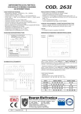
®
Made in Italy
12 PLUS
I
- SPIA DI SEGNALAZIONE DELLO
- FUNZIONE PASSO PASSO
STATO DELL'AUTOMAZIONE
- UOMO PRESENTE
- FUNZIONE OROLOGIO
- APERTURA PEDONALE
- LUCE DI CORTESIA
- DIAGNOSTICA A LED LUMINOSI
MONOFASE PER SCORREVOLE
NYOTA 115
LIBRETTO DI ISTRUZIONI
GB
12 PLUS
- STEP BY STEP OPERATIONS
- HOLD-ON SWITCHED
(DEADMAN) CONTROL
- PEDESTRIAN OPENING
- COURTESY LIGHT
SINGLE-PHASE FOR NYOTA 115
SLIDING GATE OPERATOR
INSTRUCTIONS
12 PLUS
F
- SIGNALISATION DE L'ETAT DE
- FONCTION PAS-PAS
L'AUTOMATION PAR LED
- HOMME MORT
- FONCTION HORLOGE
- OUVERTURE PIETON
- LAMPE D’ECLAIRAGE
- DIAGNOSE A LED VOYANT A DIODE
MONOPHASE POUR OUVRE-PORTAIL
COULISSANT NYOTA 115
NOTICES D'INSTRUCTION
12 PLUS
D
- SCHRITT-IMPULS-FUNKTION
- TOTMANN-BEDIENUNG
- GEHTÜRFUNKTION
- BEDIENUNGSLICHT
- DIAGNOSE-LED
EINPHASIG FÜR
SCHIEBETORANTRIEBE NYOTA 115
ANLEITUNG
12 PLUS
E
- AUTOMATION-STATUS
ANZEIGELAMPE
- UHR-FUNKTION
- LÁMPARA TESTIGO QUE
- FUNCIONAMIENTO PASO A PASO
SEÑALA ELE ESTADO DEL
- HOMBRE PRESENTE
AUTOMATISMO
- ABERTURA PARA PASO DE PEATONES
- FUNCIÓN RELOJ
- LUZ AUXILIAR
- DIAGNOSTICO POR MEDIO DE LED LUMINOSOS
MONOFASICO PARA VERJAS
DESLIZANTES NYOTA 115
FOLLETO DE INSTRUCCIONES
Dis. N. 4086
- FAULT INDICATION BY LEDs
- GATE STATUS INDICATION
- TIME CLOCK OPTION
®
s.n.c.
Via Mantova, 177/A - 37053 Cerea (Verona) Italy - Tel. +39 0442 330422 r.a.
Fax +39 0442 331054 - e-mail: [email protected] - www.fadini.net
12 PLUS
PULIN 3
L2
L3
L5
L4
3 28 27 26
L6
L7
L8
SUPPORTO
PER SCHEDA
RADIO AD
INNESTO
ELPRO 12 PLUS
I
L9
Fusibile F4 = 1A
Protezione 24V
Trasformatore
TRASFORMATORE
Fusibile F3 = 630mA
Protezione Trasformatore
Fusibile F2 = 8A
Linea
DIP-SWITCH
L1
ON
TRIMMER
1 2 3 4 5 6 7 8
1
2
3
8
9
10
11 12 13 14 15
23 24
29 30
16 17 18 19 20
21 22
CONDENSATORE
LUCE DI CORTESIA
100W max.
CONTATTO DI SICUREZZA
COMUNE
PULSANTIERA
FOTOCELLULE E
COSTE PNEUMATICHE
M
MOTORE
ELETTRICO
MONOFASE
ALIMENTAZIONE
230V MONOFASE
7
LAMPEGGIATORE
230V 25W max.
6
COMUNE
5
R62
APERTURA PEDONALE
da 3 a 30s
LUCE DI CORTESIA
da 2 a 255s
TEMPO DI PAUSA
da 2 a 128s
TEMPO DI LAVORO
APRE/CHIUDE
da 2 a 128s
4
USCITA 24V (Carico max.:
n°2 coppie di Fotocellule
n°1 Radio Ricevente)
SPIA DI SEGNALAZIONE
24V max. 3W
FINECORSA APERTURA
R63
+
FINECORSA CHIUSURA
+ -
COMUNE FINECORSA
R64
-
BLOCCO
+
CONTATTO RADIO
R65
-
APRE
+
CHIUDE
-
Fusibile F1 = 8A
Linea
OFF
Il programmatore Elpro 12 Plus di nuova generazione, è utilizzato negli apricancelli scorrevoli Nyota 115. Alimentato a 230V monofase, risponde alle normative di sicurezza
di Bassa Tensione BT 93/68/CE e Compatibilità Elettromagnetica EMC 93/68/CE, e pertanto si consiglia l'installazione da parte di personale tecnico qualificato secondo le
normative di sicurezza vigenti. La Ditta costruttrice non si assume responsabilità circa l'uso improprio del programmatore; inoltre si riserva di apportare modifiche e
aggiornamenti al programmatore e al presente libretto.
IMPORTANTE:
- Il programmatore deve essere installato in un luogo protetto e asciutto con la propria scatola di protezione.
- Applicare un Interruttore Magneto-Termico differenziale del tipo 0,03A ad alta sensibilità all'alimentazione del programmatore.
- Per Alimentazione, Motore elettrico, Lampeggiante usare cavi con fili da 1,5 mm2 fino a 50m di distanza; per Finecorsa e accessori vari utilizzare
cavi con fili da 1mm2.
- Se non si usano le Fotocellule eseguire un ponte tra i morsetti 1 e 2.
- Se non si usa nessuna Pulsantiera eseguire un ponte tra i morsetti 3 e 6.
N.B: Per applicazioni quali accensione luci, telecamere, ecc. utilizzare Relè Statici per non creare disturbi al microprocessore.
DIP-SWITCH
Dip-Switch:
1= ON Fotocellula ferma in apertura
2= ON Radio non inverte in apertura
1 2 3 4 5 6 7 8
3= ON Chiude in Automatico
4= ON Prelampeggio Attivo
5= ON Radio passo-passo con blocco intermedio
6= ON Servizio a uomo presente (Dip 4=OFF e Dip 3=OFF)
7= ON Lampeggiatore spento durante la pausa in Automatico
8= OFF, libero
ON
OFF
Nel caso di mancato funzionamento:
- Controllare la tensione di alimentazione 230V 50 Hz
monofase
- Controllare i fusibili
- Controllare che le Fotocellule siano in contatto chiuso
- Controllare tutti i contatti chiusi NC
- Controllare che non ci sia una caduta di tensione tra
programmatore e motore elettrico
Led di Diagnostica:
L1= Alimentazione 230V 50Hz è acceso
L2= Fotocellule, si spegne ad ostacolo presente
L3= Apre, si illumina ad impulso del comando di apertura
L4= Chiude, si illumina ad impulso del comando di chiusura
L5= Blocco, si spegne ad impulso del comando di stop
L6= Radio, si illumina ad ogni impulso dal trasmettitore
L7= Stato dell’automazione, lampeggia durante il movimento
L8= Finecorsa chiude, spento a cancello chiuso
L9= Finecorsa apre, spento a cancello aperto
®
Dis. N.
4086
Made in Italy
12 PLUS
I
COLLEGAMENTI ELETTRICI IN BASSA TENSIONE
Fotocellule e Costa di sicurezza:
Pulsantiera:
Finecorsa:
DIP-SWITCH 1:
3 28 27 26
CONTATTO
RADIO
Led di segnalazione dei
comandi Apre -Blocco Chiude
COMUNE
OFF: Inverte la marcia ad ogni impulso
ON: Passo passo con blocco intermedio
5
FINECORSA
APERTURA
Pulsantiera Pulin3:
ON: Non inverte in apertura
2
9 10
COMUNE
OFF: Fotocellula non ferma in apertura e
inverte in chiusura in presenza di
ostacolo
DIP-SWITCH 2 e 5 (NON devono mai essere
contemporaneamente ON):
7
COMUNE
11
8
FINECORSA
CHIUSURA
1
OFF: Funzionamento normale
Spia 24V 3W di Segnalazione:
3
BLOCCO
USCITA 24V (CARICO MAX:
N°2 COPPIE DI FOTOCELLULE
N°1 RADIO RICEVENTE)
3
- Apre/Chiude (normale)
- Inversione di marcia
ad ogni impulso
- Passo Passo
CHIUDE
Contatto Radio:
6
ON: Fotocellula ferma in apertura e
inverte in chiusura a ostacolo rimosso
12 13
CONTATTO PER
FOTOCELLULE E
COSTE DI SICUREZZA
5
APRE
2
4
COMUNE
1
3
Contatto di sicurezza:
Spia Accesa = Cancello Aperto
Spia Spenta = Cancello Chiuso
Lampeggia a 0,5s (veloce)= movimento di chiusura
Lampeggia a 1s (normale)= movimento di apertura
Lampeggia a 2s (lento)= automazione in blocco
Per far funzionare il
Programmatore
bisogna eseguire
questo contatto NC
14 15
COLLEGAMENTI ELETTRICI DI POTENZA
Condensatore e Motore Monofase:
29 30
COMUNE
Condensatore
20µF per 0,5CV
40µF per 1,0CV
Lampeggiante:
R65
16 17 18
R64
Alimentazione:
DIP-SWITCH 4 e 7:
19 20
21 22
OFF: Senza prelampeggio
-
+
TEMPO DI
LAVORO
APRE/CHIUDE
DA 2 A 128s
M
-
Lampada di cortesia
230V max 100W:
ON: Prelampeggio
23 24
4
+
TEMPO DI
PAUSA
DA 2 A 128s
ON: Lampeggiatore Disattivato
durante la pausa in automatico
7
230V MAX 25W
-
ALIMENTAZIONE
230V 50Hz MONOFASE
OFF: Lampeggia durante la pausa
in automatico
Trimmer R63
+
LUCE DI
CORTESIA
DA 2 A 255s
FUNZIONI
Automatico/ Semiautomatico:
Ciclo Automatico: ad un impulso di comando di apertura, il cancello
Apre, si ferma in Pausa del tempo impostato dal trimmer R64,
terminato il quale Chiude automaticamente
Ciclo Semiautomatico: ad un impulso di comando di apertura il
cancello si Apre e poi ferma in apertura. Per Chiudere bisogna dare
l'impulso di chiusura.
3
OFF= Non chiude in Automatico.
Funzione Semiautomatico
Trimmer R62
da 3 a 30s Attivabile con un impulso di
comando (anche radio), di durata
superiore ai 2s
3
4
APRE
+
Tempo di Pausa
da 2 a 128s
Uomo Presente:
Si ottiene il comando di apertura e chiusura "ad azione
mantenuta" (senza autotenuta nei Relè), quindi l'attiva
presenza dell'operatore durante tutto il movimento
dell'automazione fino al rilascio del pulsante o della
chiave del selettore
DIP-SWITCH 6
ON= Uomo Presente con Dip-switch 4=OFF
e Dip-switch 3=OFF
6
OFF= Funzionamento Normale
Funzionamento: programmare l'orario di apertura sull'orologio, all'ora impostata il cancello effettuerà l'apertura rimanendo aperto, e non accetterà
più nessun comando (anche radio) sino allo scadere del tempo impostato sull'orologio, allo scadere del quale dopo il tempo di pausa seguirà
la chiusura automatica.
3 4
Il Trimmer R62 lasciato a zero, Dip-Switch N°3=ON.
NA
COMUNE
3
APRE
ON= Chiude in Automatico
+
Trimmer Pedonale R62 va
lasciato a zero
COMUNE
DIP-SWITCH N°3=ON Chiusura Automatica
-
+
COMUNE
ON= Chiude in Automatico
Orologio:
-
DIP-SWITCH 3
Trimmer R64
-
Apertura Pedonale:
OFF= Non chiude in Automatico
Funzione Semiautomatico
®
Dis. N.
4086
Made in Italy
PULIN 3
L2
L3
3 28 27 26
L5
L4
ELPRO 12 PLUS
12 PLUS
GB
L6
L7
RADIO
PLUG-IN
CARD
CONNECTOR
F4 Fuse = 1A
24V Transformer
Protection
TRANSFORMER
F3 Fuse = 630mA
Transformer Protection
L8
L9
F2 Fuse = 8A
Mains
DIP-SWITCH
L1
ON
TRIMMER
1 2 3 4 5 6 7 8
9
10
11 12 13 14 15
23 24
29 30
16 17 18 19 20
21 22
M
SINGLE-PHASE
ELECTRIC
MOTOR
230V SINGLE-PHASE
VOLTAGE SUPPLY
PEDESTRIAN OPENING
from 3 up to 30s
8
230V 25W max.
FLASHING LAMP
COURTESY LIGHT
from 2 up to 255s
7
NEUTRAL
DWELL TIME
from 2 up to 128s
6
CAPACITOR
MOTOR RUN TIME
OPEN/CLOSE
from 2 up to 128s
5
COURTESY LIGHT
100W max.
R62
4
SAFETY CONTACT
R63
3
NEUTRAL
PUSH BUTTONS
R64
2
PHOTOCELLS
SAFETY EDGES
R65
1
24V OUTPUT (max. load:
2 PAIRS PHOTOCELLS
1 RADIO RECEIVER)
INDICATION LAMP
24V max. 3W
LIMIT SWITCH OPEN
+
LIMIT SWITCH CLOSE
+ -
LIMIT SWITCH NEUTRAL
-
STOP
+
RADIO CONTACT
-
OPEN
+
CLOSE
-
F1 Fuse = 8A
Mains
OFF
The electronic control panel Elpro 12 Plus, new generation, is designed to operate the sliding gate operator Nyota 115. Power supply is 230V 50Hz single-phase. Built in
full compliance with BT 93/68/CE Low Voltage and EMC 93/68/CE Electro-Magnetic Compatibility Regulations. Fitting operations are recommended by a qualified technician
in conformity to the existing safety standards.
The manufacturing company declines any responsability for incorrect handling and application; also, it reserves the right to change or update the control panel any time.
PLEASE NOTE:
- The control panel must be installed in a sheltered, dry place, inside the box provided with it.
- Fit the mains to the control panel with a 0.03A high performance circuit breaker.
- Use 1.5mm2 section wires for voltage supply, electric motor and flashing lamp.
Maximum recommended distance 50m.
Use 1mm2 section wires for limit switches, photocells, push-buttons/key-switch and accessories.
- Bridge terminals 1 and 2 if no photocells are required.
- Bridge terminals 3 and 6 if no key- or push-button switches are required.
N.W: To fit extra accessories such as lights, CCTV etc. use only solid state relays to prevent damages to the microprocessor.
Dip-Switch:
1= ON. Photocells. Stop while opening
2= ON. Radio. No reversing while opening
1 2
3= ON. Automatic closing
4= ON. Preflashing activated
5= ON. Radio. Step by step. Stop in between
6= ON. Dead Man Control (Dip 4=OFF and Dip 3=OFF)
7= ON. No lamp on during dwell time
8= OFF. No function
DIP-SWITCH
ON
3 4 5 6 7 8
OFF
In case of failure of the panel:
- Check voltage supply. It must be 230V 50Hz single-phase
- Check fuses
- Check photocells if contacts are normally closed
- Check all NC contacts
- Check that no voltage drop has occurred from the control
panel to the electric motor
Led Status Indication:
L1= 230V 50Hz power supply. Alight
L2= Photocells, if obstructed light goes off
L3= Open. Alight whenever an Open pulse is given
L4= Close. Alight whenever a Close pulse is given
L5= Stop. It goes off on pulsing Stop
L6= Radio. It goes on by pressing a transmitter button
L7= Gate Status; it flashes on gate opening
L8= Limit switch Close; off when gate is closed
L9= Limit switch Open; off when gate is open
®
Drwg. No. 4086
Made in Italy
12 PLUS
GB
LOW VOLTAGE ELECTRICAL CONNECTIONS
Photocells and Safety Edge:
Button switch:
Limit switch:
DIP-SWITCH 1:
8
LIMIT SWITCH
OPEN
NEUTRAL
3 28 27 26
RADIO
CONTACT
Led to indicate status of
Open - Stop - Close
switches
NEUTRAL
OFF: Any pulse reverses the gate
ON: Step by step. Stop in between
5
LIMIT SWITCH
CLOSE
ON: Gate is not reversed while opening
2
9 10
Push Button Switch Pulin 3:
DIP-SWITCH 2 and 5 (NEVER set BOTH of them ON
at the same time):
7
COMMON/
NEUTRAL
11
OFF: Photocells do not stop gate while
opening, reverse it in case of an
obstacle
1
OFF: Standard operating mode
24V 3W Indication Light:
3
STOP
3
- Open/Close (Standard)
- Travel reversing on
pulsing
- Step by step
CLOSE
24V OUTPUT (MAX. LOAD:
2 PAIRS PHOTOCELLS
1 RADIO RECEIVER)
Radio Contact:
6
ON: Photocells stop gate while opening,
reverse it once obstacle is removed
12 13
PHOTOCELLS
AND SAFETY EDGE
5
OPEN
2
4
COMMON/
NEUTRAL
1
3
Safety Contact:
Light ON = Open gate
Light OFF = Closed gate
Flashing (fast) 0.5s= Closing gate
Flashing (normally) 1s= Opening gate
Flashing (slowly) 2s= gate is stopped
14 15 This contact must be
N.C. for the control
panel to be allowed to
work
HIGH VOLTAGE ELECTRICAL CONNECTIONS
Capacitor and Single-phase Motor:
29 30
16 17 18
M
R64
19 20
Power supply:
DIP-SWITCH 4 and 7:
ON: Pre-flashing
21 22
OFF: No pre-flashing
NEUTRAL
Capacitor
20µF for 0.5HP
40µF for 1.0HP
Flashing lamp:
R65
-
+
-
23 24
4
+
MOTOR RUN
DWELL TIME
TIME
FROM 2 UP TO 128s
OPEN/CLOSE
FROM 2 UP TO 128s
ON: Lamp is not operating during
Dwell time. Automatic mode.
7
230V MAX 25W
POWER SUPPLY
230V 50Hz SINGLE-PHASE
OFF: It flashes during Dwell Time.
Automatic Mode.
Courtesy Light
230V max. 100W:
Trimmer R63
-
+
COURTESY LIGHT
FROM 2 UP TO 255s
OPERATING MODES
Automatic / Semiautomatic:
Automatic Operation: any pulse opens the gate, the gate stays
open as long as the Dwell time expires as set by R64 trimmer, then
it closes automatically, no pulsing is required.
Semi-automatic Operation: any pulse opens the gate that stays
open. A second pulse to Close is required for the gate to close.
3
OFF= No Automatic. Semi-automatic
closing by pulse
Trimmer R62
from 3 to 30s. It can be activated by
any pulse (eg. by remote control)
superior to 2s
3
4
Hold on switched (Deadman) control:
Open and Close operations are achieved "by holding a
switch on" (no relay self-holding in involved) therefore a
phisical attendance is required to keep the gate opening
or closing until either the button or key is released.
DIP-SWITCH 6
ON= Deadman Control. Dip-switch 4=OFF
and Dip-switch 3=OFF
OPEN
+
Dwell Time
from 2 to 128s
6
OFF= Standard Operations
How it works: Set the clock to the required times. On the pre-set time the gate is automatically opened and held open. Any further pulsing (even
by remote control) is not accepted by the system until the time pre-set by the clock has expired. On expiring and after the pre-set dwell time
the gate is closed automatically.
3 4
R62 trimmer on to zero, Dip-Switch 3=ON.
3
NO
COMMON
Pedestrian Trimmer R62
set on to zero
OPEN
ON= Automatic Closing
+
COMMON
DIP-SWITCH No.3=ON Automatic Closing
-
+
COMMON
ON= Automatic Closing
Time clock:
-
DIP-SWITCH 3
Trimmer R64
-
Pedestrian Opening:
OFF= No Automatic. Semi-automatic
closing by pulse
®
Drwg. No.
4086
Made in Italy
PULIN 3
L2
L3
L5
L4
ELPRO 12 PLUS
12 PLUS
F
3 28 27 26
L6
L7
L8
SUPPORT
CARTE RADIO
ENFICHABLE
Fusible F4 = 1A
Protection 24V
Transformateur
TRANSFORMATEUR
Fusible F3 = 630mA
Protection transformateur
L9
Fusible F2 = 8A
Ligne
DIP-SWITCH
L1
ON
POTENTIOMETRE
1 2 3 4 5 6 7 8
+
1
2
3
8
9 10 11 12 13 14 15
23 24 29 30
16 17 18 19 20 21 22
MOTEUR
ELECTRIQUE
MONOPHASE
ALIMENTATION
230V MONOPHASE
M
LAMPE CLIGNOTANTE
230V 25W max.
PASSAGE PIETON
DE 3 A 30s
7
COMMUN
VOYANT
DE 2 A 255s
6
CONDENSATEUR
TEMPS D'ARRÊT
DE 2 A 128s
5
VOYANT
100W max.
TEMPS DE TRAVAIL
OUVERT/FERM.
DE 2 A 128s
4
CONTACT DE SECURITE
R62
SORTIE 24V (CHARGE max.
N°.2 PAIRES CELLULES PHOTOELECTRIQUES
N°.1 RECEPTEUR RADIO)
VOYANT
24V max. 3W
FIN DE COURSE OUVERTURE
R63
COMMUN
BOITE A BOUTONS
R64
CELLULES PHOTOELECTRIQUES
LISTEAUX DE SECURITE
R65
FIN DE COURSE FERMETURE
+ -
COMMUN FIN DE COURSE
-
ARRET
+
CONTACT RADIO
-
OUVERTURE
+
FERMETURE
-
Fusible F1 = 8A
Ligne
OFF
Le programmateur Elpro 12 Plus de nouvelle conception, est utilisé avec les ouvreportails coulissant Nyota 115. Alimenté en 230V 50Hz monophasé em conformité aux
normes de sécurité de Basse Tension BT 93/68/CE et de la Compatibilité Electromagnetique EMC 93/68/CE. L'installation doit être effectuée par un technicien spécialisé,
suivant les normes de sécurité en vigueur. Le constructeur décline toute responsabilité pour l'utilisation impropre du programmateur et il se réserve le droit de modifier
ou d' apporter des modificatons au programmateur ou à cette notice à n'importe quel moment.
IMPORTANT:
- Le programmateur doit être installé dans son boîtier de protection dans un endroit abrité et sec.
- Appliquez à l'alimentation du programmateur un interrupteur Magnéto-thérmique differentiel du type 0,03A à haute sensibilité.
- Pour l'alimentation, le moteur éléctrique et la lampe de signalisation utiliser des câbles à fils de 1,5 mm2 pour distances à 50mt; pour le fin de course et les accessoires
il suffit 1mm2.
- Si l'on n'utilise pas les photocellules, accoupler à pont les bornes 1 et 2.
- Si l'on n'utilise aucun clavier accoupler à pont les bornes 3 et 6.
N.B: Pour d'applications telles que: lampes d'éclairage,télécaméra etc, utiliser des relais statiques pour ne pas avoir des perturbations du microprocesseur.
Dip-Switch:
DIP-SWITCH
1= ON Cellule arrête à l'ouverture
2= ON Radio n'inverse pas à l'ouverture
1 2 3 4 5 6 7
3= ON Ferme en Automatique
4= ON Présignalisation active
5= ON Radio pas-pas avec arrêt intermediaire
6= ON Homme mort (Dip 4=OFF et Dip 3=OFF)
7= ON Lampe de signalisation non active durant la pause en
Automatique
8= OFF, libre
ON
OFF
8
Au cas où le programmateur ne fonctionne pas:
- Contrôler la tension d'alimentation 230V 50 Hz monophasé
- Contrôler les fusibles
- Contrôler que les cellules photoélectriques soient en
contacte fermé
- Contrôler tous les contactes fermés NF
- Contrôler qu'il n'y ait pas de chute de tension entre le
programmateur et le moteur électrique
Voyants de Diagnostic:
L1= Alimentation 230V 50Hz est allumé
L2= Cellules photoélectriques, s'éteint en cas d'obstacle
L3= Ouvre, s'allume à l'impulsion de commande d'ouverture
L4= Ferme, s'allume à l'impulsion de commande de fermeture
L5= Arrêt, s'éteint à l'impulsion de commande d'arrêt
L6= Radio, s'allume à chaque impulsion de l'émetteur
L7= Etat de l'automatisme, clignote durant le mouvement
L8= Fin de course ferme, éteint à portail fermé
L9= Fin de course ouvre, éteint à portail ouvert
®
Dis. N.
4086
Made in Italy
12 PLUS
F
BRANCHEMENTS ELECTRIQUES EN BASSE TENSION
Cellules photoélectriques et listeaux de sécurité
Boîte à boutons:
DIP-SWITCH 2 et 5 (NE doivent JAMAIS être au
même temps sur ON):
7
9 10
COMMUN
CONTACT
RADIO
COMMUN
Voyant à diodes des
commandes
Ouvre - Arrêt - Ferme
OFF: Fonctionnement normale
Voyant à diodes 24V 3W :
Contact de Sécurité:
11 Voyant allumé=Portail Ouvert
3
8
3 28 27 26
OFF: Inverse la marche à chaque
impulsion
ON: Pas-pas avec arrêt intermédiaire
5
6
Boîte à boutons Pulin3:
ON: N'inverse pas en ouverture
2
5
FIN DE COURSE
OUVERTURE
3
- Ouvre/Ferme (normal)
- Inversion de marche à
chaque impulsion
- Pas-Pas
1
4
COMMUN
Contact Radio:
SORTIE 24V (CHARGE MAX:
N°2 PAIRE CELLULES
PHOTOELECTRIQUES
N°1 RECEPTEUR RADIO)
3
Fin de course:
FIN DE COURSE
FERMETURE
CONTACT POUR
CELLULES
PHOTOELECTRIQUES
ET LISTEAUX DE
SECURITE
ON: Photocellule arrête à l'ouverture et
inverse en fermeture si l'obstacl e
n'est plus présent
OFF: Photocellule n'arrête pas à
l'ouverture et inverse en fermeture
en presénce d'obstacle
ARRET
12 13
FERME
2
OUVRE
1
COMMUN
DIP-SWITCH 1:
14 15 Pour mettre en marche
Voyant Eteint=Portail Fermé
Clignotement à 0,5s (rapide)=mouvement de fermeture
Clignotement à 1s (normal)=mouvement d'ouverture
Clignotement à 2s (lent)=automatisme bloqué
le programmateur, il
fault activer le contact
N.F.
BRANCHEMENTS ELECTRIQUES
Condensateur et Moteur Monophasé:
29 30
R65
16 17 18
COMMUN
Condensateur
20µF pour 0,5CV
40µF pour 1,0CV
-
+
-
Alimentation:
DIP-SWITCH 4 et 7:
R64
TEMPS DE TRAVAIL
OUVERT./FERM.
DE 2 A 128s
M
Lampe de signalisation
19 20
Lampe d’éclairage de
230V max. 100W:
ON: Presignalisation
21 22
OFF: Sans presignalisation
+
23 24
Potentiomètre R63
4
TEMPS
D'ARRET
DE 2 A 128s
230V MAX 25W
7
ON: Lampe de signalisation non
active durant l'arrêt en
automatique
OFF: Clignotement durant l'arrêt en
automatique
ALIMENTATION
230V 50Hz MONOPHASE
-
+
LAMPE
D’ECLAIRAGE
DE 2 A 255s
FONCTIONS
Automatique/ Semiautomatique:
Cycle Automatique: à l'impulsion de commande d'ouverture le
portail Ouvre, il s'arrête en Pause pendant le temps rentré dans le
potentiomètre R64, le temps terminé il ferme automatiquement
Cycle Semiautomatique: à l'impulsion de commande d'ouverture
le portail ouvre et puis il s'arrête à l'ouverture . Pour le fermer il
faut lui donner l'impulsion de fermeture.
Potentiomètre R64
Horloge:
3
OFF= Fermeture non automatique
Fonction Semiautomatique
de 3 à 30 s Actif par une impulsion de
commande (même radio), de durée
mejeure de 2s
3
4
Homme Mort:
On obtient le mouvement d'ouverture et fermeture en
gardant la pression sur la touche ou la clé du sélecteur
(avec déclenchement des relais). quand on relâche la
pression, le mouvement s'arrête
DIP-SWITCH 6
ON= Homme Mort avec Dip-switch 4=OFF
et Dip-switch 3=OFF
6
OFF= Fonctionnement Normal
Fonctionnement: programmer l'heure d'ouverture dans l'horloge, à l'heure mémorisée le portail s'ouvrira en restant ouvert, et il ne répondra
plus à aucune commande (même radio) jusqu'au temps rentré dans l'horloge, quand le temps est terminé après le temps de pause on aura la
fermeture automatique.
3 4
Le Potentiomètre R62 à zéro, Dip-Switch N°3=ON.
3
NO
COMMUN
Le potentiomètre R62
piétons doit être laissé à
zéro
ON= Ferme en Automatique
OFF= Ne ferme pas en
Automatique
Fonction Semi-automatique
OUVRE
+
COMMUN
DIP-SWITCH N°3=ON Fermeture Automatique
-
Potentiomètre R62
OUVRE
+
+
COMMUN
-
-
DIP-SWITCH 3
ON= Fermeture automatique
Temps de Pause de
5 à 128s
Ouverture Piétons:
®
Dis. N.
4086
Made in Italy
D
12 PLUS
Die Steuerung Elpro 12 Plus, neuer Konzeption, wird für die Schiebetorantriebe Nyota 115 verwendet. Einphasige bzw. dreiphasige 230V 50Hz Versorgung entspricht
den Sicherheitsnormen, was Niederspannung BT 93/68/EG und elektromagnetische Kompatibilität EMC 93/68/EG betrifft. Die Installation muss durch qualifizierte Fachleute
gemäss den gültigen Vorschriften erfolgen. Die Herstellerfirma übernimmt keine Haftung für eine falsche Verwendung des Apparats und behält sich vor, Änderungen und
Verbesserungen an der Steuerung vorzunehmen.
ACHTUNG:
- Die Steuerung muss an einem trockenen Ort installiert und durch ein zusätzliches Gehäuse geschützt werden.
- Der Steuerung einen hochempfindlichen magneto-thermischen Differenzialschalter Typ 0,03A vorschalten.
- Für Versorgung, E-Motor und Blinkleuchte Kabel mit Drähten von 1,5 mm2 Durchschnitt bis zum Abstand von 50m verwenden; für Endschalter und
Zubehör Kabel mit Drähten von 1 mm2 Durchschnitt.
- Werden keine Lichtschranken verwendet, müssen die Klemmen 1 u. 2 überbrückt werden.
- Werden keine Drucktasten verwendet, müssen die Klemmen 3 u. 6 überbrückt werden.
NB: Werden Zusätze wie Videokameras, Leuchten etc. angeschlossen müssen statische Relais verwendet werden, da ansonsten Störungen beim Mikroprozessor auftreten
können.
DIP-SWITCH
Dip-Schalter:
1= ON Lichtschranke. Stoppt während der Öffnung
2= ON Funk. Keine Umkehr während der Öffnung
1 2 3 4 5 6 7
3= ON Automatisches Schliessen
4= ON Vorblinken aktiv
5= ON Funkkontakt. Schritt für Schritt. Mittelstopp
6= ON Totmannbetrieb (Dip 4=OFF und Dip 3=OFF)
7= ON Ausgeschaltete Blinkleuchte während der Haltezeit. Automatisch
8= OFF Frei
ON
8
OFF
Fehlersuche bei Betriebsstörung der Steuerung:
- Kontrollieren Sie die Spannung. Sie muss 230V 50 Hz einphasig
betragen
- Kontrollieren Sie die Sicherungen
- Kontrollieren Sie, ob die Lichtschranken einen N.C. Anschluss
aufweisen
- Kontrollieren Sie alle geschlossene Kontakte N.C.
- Kontrollieren Sie, dass zwischen Steuerung und E-Motor kein
Spannungsabfall vorliegt.
Diagnose-Leds:
L1= Unter 230V 50Hz Versorgungsspannung. Erleuchtet
L2= Lichtschranke, erlischt wenn ein Hindernis den Lichtstrahl unterbricht
L3= Öffnen. Erleuchtet bei einer Auf-Impulsgabe
L4= Schliessen. Erleuchtet bei einer Zu-Impulsgabe
L5= Halt. Erleuchtet bei einer Stopp-Impulsgabe
L6= Funk. Erleuchtet bei jeder Impulsgabe des Senders
L7= Automation-Status. Blinkt während des Laufes
L8= Endschalter bei Schliessung. Aus, wenn das Tor geschlossen ist
L9= Endschalter bei Öffnung. Aus, wenn das Tor offen ist
®
Zeichn. Nr. 4086
Made in Italy
12 PLUS
D
NIEDERSPANNUNGSANSCHLÜSSE
DIP-SCHALTER 1:
Lichtschranken und Sicherheitsleiste:
1
2
12 13
KONTAKT FÜR
LICHTSCHRANKEN
UND
SICHERHEITSLEISTEN
AUSGANG 24V
(HÖCHSTBELASTUNG MAX: Nr.2
LICHTSCHRANKEN
Nr.1 FUNKEMPFÄNGER)
Funkkontakt:
3
- Öffnen/Schliessen
(normal)
- Umkehr bei jeder
Impulsgabe
- Schritt-Impuls-Funktion
1
DIP-SCHALTER 2 u. 5 (Sie müssen NIE gleichzeitig
auf ON gestellt sein):
7
3 28 27 26
OFF: Umkehr bei jeder Impulsgabe
FUNKKONTAKT
ON: Schritt für Schritt mit Zwischenhalt
5
Anzeige-Led des
Öffnen-StoppSchliessen Schalters
MITTELLEITER
2
MITTELLEITER
11
Drucktaster Pulin3:
ON: Keine Umkehr während der Öffnung
OFF: Normalbetrieb
Anzeigelicht 24V 3W:
3
ON : Lichtschranke stoppt während der
Öffnung, kehrt bei Schliessung nach
Entfernung des Hindernisses um
OFF : Lichtschranke stoppt nicht während
der Öffnung, kehrt während der
Schliessung beim Hindernis um
Sicherheitskontakt:
Anzeigelicht An = offenes Tor
Anzeigelicht Aus = geschlossenes Tor
0,5s Blinken (schnell)= Schliessbewegung
1s Blinken (normal)= Öffnungsbewegung
2s Blinken (langsam)= blockierte Automation
14 15 Für den Betrieb der
Steuerung muss dieser
Kontakt geschlossen
(N.C.) sein
HOCHSPANNUNGSANSCHLÜSSE
Kondensator und einphasiger Motor:
29 30
R65
16 17 18
MITTELLEITER
Kondensator
20µF für 0,5PS
40µF für 1,0PS
Blinkleuchte:
R64
19 20
ON: Vorblinken
21 22
OFF: Ohne Vorblinken
-
+
-
23 24
+
BETRIEBSZEIT
PAUSEZEIT VON
ÖFFNEN/SCHLIESSEN 2 BIS 128s
VON 2 BIS 128s
M
Bedienungslicht 230V
max 100W:
Versorgung:
DIP-SCHALTER 4 und 7:
ON: Blinkleuchte ist während der
Haltezeit ausgeschaltet
7
230V MAX 25W
-
SPANNUNG
230V 50Hz EINPHASIG
OFF: Sie blinkt während der Haltezeit.
Automatischer Betrieb
Trimmer R63
+
BEDIENUNGSLICHT
VON 2 BIS 255s
FUNKTIONEN
Automatisch/ Halbautomatisch:
Automatisches Zyklus: bei einer Auf-Impulsgabe öffnet sich das
Tor, stoppt bei Haltezeit um die auf dem Trimmer R64 eingestellte
Zeit, danach schliesst es automatisch.
Halbautomatisches Zyklus: bei einer Auf-Impulsgabe öffnet sich
das Tor und dann stoppt. Zur Schliessung muss man eine ZuImpulsgabe geben.
ON= Automatische Schliessung
-
+
3
Haltezeit
von 2 bis 128s
OFF= Keine automat.Schliessung
Halbautomatische Funktion
+
Trimmer R62
3
4
Totmann-Bedienung:
Öffnungs- und Schliessungs-Bedienung "durch
gehaltene Betätigung" (kein Selbsthalten des Relais),
d.h. dass die aktive Anwesenheit des Bedieners
während der Automation-Bewegung nötig ist, bis die
Taste oder der Schlüssel des Schalters losgelassen
wird.
DIP-SCHALTER 6
ON= Totmann-Bedienung mit Dip-Schalter 4=OFF
und Dip-Schalter 3=OFF
6
OFF= Normale Funktion
Betrieb: die Öffnungszeit auf die Uhr einstellen, bei der eingestellten Zeit wird das Tor öffnen und offen bleiben und keine Impulsgabe (Funk)
ansprechen bis die auf die Uhr eingestellte Zeit abgelaufen ist. Bei abgelaufener Zeit nach der Haltezeit folgt die automatische Schliessung.
Das Trimmer R62 muss auf Null eingestellt werden, Dip-Schalter Nr.3=ON.
3 4
Uhr:
NO
MITTELLEITER
3
OFF= Kein automat. Schliessen
Halbautomatische Funktion
OFFEN
ON= Automatisches Schliessen
+
Trimmer R62 für
Gehtürfunktion auf Null
einstellen
MITTELLEITER
DIP-SCHALTER Nr.3=ON Automatisches Schiessen
-
-
von 3 bis 30s wird durch eine
Impulsgabe (auch Funkimpuls) länger
als 2s betätigt
MITTELLEITER
DIP-SCHALTER 3
Trimmer R64
Gehtürfunktion:
®
Zeichn. Nr.
4086
Made in Italy
PULIN 3
L2
L3
L5
L4
ELPRO 12 PLUS
12 PLUS
E
3 28 27 26
L6
L7
L8
SOPORTE
PARA FICHA
RADIO
ENCHUFABLE
Fusible F4 = 1A
Protección 24V
Transformador
TRANSFORMADOR
Fusible F3 = 630mA
Protección transformador
L9
Fusible F2 = 8A
Linea
DIP-SWITCH
L1
ON
TRIMMER
1 2 3 4 5 6 7 8
9
10
11 12 13 14 15
23 24
29 30
16 17 18 19 20
21 22
M
MOTOR
ELECTRICO
MONOFASICO
ALIMENTACIÓN
230V MONOFASICO
ABERTURA PARA PASO
DE PEATONES
DESDE 3 HASTA 30s
8
DESTELLADOR
230V 25W max.
LUZ AUXILIAR
DESDE 2 HASTA 255s
7
COMUN
TIEMPO DE PAUSA
DESDE 2 HASTA 128s
6
CONDENSADOR
TIEMPO DE TRABAJO
DE ABRE/CIERRE
DESDE 2 HASTA 128s
5
LUZ AUXILIAR
100W max.
R62
4
CONTACTO DE SEGURIDAD
R63
3
COMUN
PULSADOR
R64
2
FOTOCÉLULAS Y
NERVADURAS NEUMÁTICAS
R65
1
SALIDA 24V (CARGA MAX:
Núm.2 pares de Fotocélulas
Núm.1 Radiorreceptor)
LAMPARA TESTIGO
24V max. 3W
TOPE DE RECORRIDO DE ABERTURA
+
TOPE DE RECORRIDO DE CIERRE
+ -
COMUN TOPE DE RECORRIDO
-
BLOQUEO
+
CONTACTO RADIO
-
ABRE
+
CIERRA
-
Fusible F1 = 8A
Linea
OFF
Se emplea el programador Electrónico Elpro 12 Plus de nueva generación en los abre-verjas deslizantes Nyota 115. El mismo está alimentado con corriente monofásica
de 230V 50Hz y cumple con la reglamentación de seguridad de Baja Tensión BT 93/68/CE y Compatibilidad Eletromagnética EMC 93/68/CE. Se aconseja por consiguiente
encargar su instalación a personal técnico calificado profesionalmente, con arreglo a la reglamentación de seguridad vigente. La empresa constructora rehúsa cualquier
responsabilidad en caso de empleo improprio del programador.
La misma se reserva además el derecho de modificar y poner al dia en cualquier momento ya sea el programador como este folleto.
IMPORTANTE:
- Hay que instalar el programador en un lugar seco al interior de su propia caja protectora.
- Hay que aplicar un interruptor magneto-térmico diferencial del tipo de 0,03A de alta sensibilidad a la corriente de alimentación
del programador.
- Para la alimentación, el motor eléctrico y el destellador, amplear hilos de tamaño igual a 1,5mm2, para una distancia de hasta
50 metros. Para los topes de recorrido, las fotocélulas, el tablero de pulsadores y los accesorios, emplear cables con hilos de 1mm2.
- Si no se emplean las fotocélulas hay que hacer el puente entre los bornes 1 y 2.
- Si no se emplea ningún tablero de pulsadores hay que hacer el puente entre los bornes 3 y 6.
N.B: Para las aplicaciones especiales, por ejemplo, encendidos do alumbrado, telecámaras, etc., hay que emplear unos Relès Estàticos; de otra forma, con relés normales
se pueden causar interferencias an el microprocesador.
Dip-Switch:
DIP-SWITCH
1= ON La fotocélula para en la abertura
2= ON El radiomando no invierte
1 2 3 4 5 6 7
3= ON Cierre en automático
4= ON Pre-relampagueo activo
5= ON Radio paso a paso con bloqueo intermedio
6= ON Funcionamiento de "Hombre Presente"
(Dip 4=OFF y Dip 3=OFF)
7= ON Destellador apagado durante la pausa en Automático
8= OFF Libro
ON
8
OFF
SI FALLA EL FUNCIONAMIENTO DEL PROGRAMADOR, HAY
QUE:
- Controlar la tensión de alimentación, tiene que ser 230V
50 Hz nonofásica
- Controlar los fusibles
- Controlar las fotocélulas, que estén en contacto cerrado
- Controlar todos los contacto cerrado NC
- Controlar que no haya una calda de voltaje entre el
programador y el motor eléctrico
Led de Diagnostico:
L1=La alimentación a 230V 50Hz está encendida
L2=Fotocélulas. Se apaga en caso de que haya un obstáculo
L3=Abre, se enciende en cuanto se dé el impulso de mando de abertura
L4=Cierre, se enciende en cuanto se dé el impulso de mando de cierre
L5=Bloqueo, se apaga en cuanto se dé el impulso de mando de stop
L6=Radio, se enciende a cada impulso desde el transmisor
L7=Estado del automatismo, ralampaguea durante el movimiento
L8=Tope de recorrido de cierre, está apagado cuando la verja está cerrada
L9=Tope de recorrido de abertura, está apagado cuando la verja está abierta
®
Dib. Núm. 4086
Made in Italy
12 PLUS
E
CONEXIONES ELECTRICAS EN BAJA TENSION
Tablero de
pulsadores:
Fotocelulas y nervadura de seguridad:
DIP-SWITCH 1:
OFF: Invierte la marcha a cada impulso
ON: Paso a paso con bloqueo
intermedio
OFF: Funcionamiento normal
Lámpara testigo de 24V 3W de señalización:
11
3 28 27 26
COMUN
RADIOCONTACTO
COMUN
5
9 10
Tablero de pulsadores Pulin3:
ON: No invierte en abertura
2
8
TOPE DE
RECORRIDO
ABERTURA
DIP-SWITCH 2 y 5 (NO tienen que estar NUNCA ON
al mismo tiempo):
7
6
COMUN
3
- Abre/Cierre (normal)
- Inversión de marcha a
cada impulso
- Paso a paso
5
TOPE DE
RECORRIDO
CIERRE
Radiocontacto:
1
4
BLOQUEO
SALIDA 24V (CARGA MAX:
Núm.2 PARES FOTOCELULAS
Núm.1 RADIORRECEPTOR)
3
COMUN
CONTACTO
FOTOCELULAS Y
NERVADURAS DE
SEGURIDAD
3
ON: La fotocélula está parada en
abertura y invierte en cierre,
habièndose removido el obstáculo
OFF: La fotocélula no está parada en
abertura y invierte en cierre,
habièndo un obstáculo
12 13
ABRE
2
CIERRA
1
Tope de recorrido:
Led de señalización de
los mandos:
Abre - Bloqueo - Cierre
Contacto de seguridad:
Lámpara testigo Encendida = Verja abierta
Lámpara testigo Apagada = Verja cerrada
Relampagueo a 0,5s (rápida)= movimiento de cierre
Relampagueo a 1s (normal)= movimiento de abertura
Relampagueo a 2s (lento)= automatismo bloqueado
14 15 Para hacer funcionar el
Programador hay que
realizar este contacto
N.C.
CONEXIONES ELECTRICAS DE POTENCIA
Condensador y Motor Monofásico:
29 30
16 17 18
R64
Alimentación:
DIP-SWITCH 4 y 7:
19 20
Luz auxiliar
230V max 100W:
ON: Pre-relampagueo
21 22
COMUN
Condensador
20µF para 0,5CV
40µF para 1,0CV
Destellador:
R65
-
+
TIEMPO DE TRABAJO
DE ABRE/CIERRE
DESDE 2 HASTA 128s
M
-
4
+
TIEMPO DE
PAUSA
DESDE 2
HASTA 128s
ON: El destellador está desactivado
durante la pausa en automático
OFF: El destellador relampaguea
durante la pausa en automático
7
230V MAX 25W
23 24
OFF: Sin pre-relampagueo
SUMINISTRO
230V 50Hz MONOFASICO
Trimmer R63
-
+
LUZ AUXILIAR
DESDE 2 HASTA 255s
FUNCIONAMIENTO
Automático/ Semi-automático:
Ciclo Automático: dando un impulso de mando de abertura, la
verja se Abre, se para en Pausa durante el lapso de tiempo que
está planteado por el "Trimmer" R64, después de lo cual la verja
se Cierra automáticamente.
Ciclo Semi-automático: dando un impulso de mando de abertura,
la verja se Abre y a continuación se para en abertura. Para cerrarla
hay que dar el impulso de cierre.
Abertura para paso de
peatones:
Trimmer R62
-
+
DESDE 3 HASTA 30 s - Se puede activar por
un impulso de mando (hasta por radio) con
duración mayor de 2 s
DIP-SWITCH 3
Trimmer R64
3
Hombre Presente:
Se logra mandar la abertura y cierre "de acción
mantenida" (sin autorretención en el Relé), por
consiguiente la presencia activa del operador durante
todo el movimiento de la automatización hasta tanto que
se suelte el pulsador o la llave del selector.
DIP-SWITCH 6
4
ON: Hombre Presente con
Dip-switch 4=OFF y Dip-switch 3=OFF
ON= Cierre Automático
Reloj:
3
OFF= Non cierre en automático.
Función semi-automática
6
OFF: Funciónamiento Normal
Funcionamiento: programar en el reloj el horario de abertura: a la hora que está planteada, la verja se abrirá y se quedará abierta el automatismo
no va a aceptar ningún mando ulterior (hasta por radio) hasta tanto que haya transcurrido el lapso de tiempo planteado en el reloj; una vez acabado
dicho tiempo, después del tiempo de pausa, se realizará el cierre automático.
Hay que dejar en cero el "Trimmer" para paso de peatones R62,
3 4
DIP-SWITCH Núm.3=ON Cierre Automático.
ON= Cierre en automático
3
OFF= Non cierre en automático.
Función semi-automática
NA
COMUN
ABRE
+
Hay que dejar en cero
el Trimmer para paso de
peatones R62
COMUN
DIP-SWITCH Núm.3=ON Cierre Automático
-
ABRE
+
COMUN
-
Tiempo de Pausa desde
5 hasta 128s
®
Dib. Núm.
4086
Made in Italy
I - Prima dell'installazione da parte di personale tecnico qualificato, si consiglia di prendere visione del
Libretto Normative di Sicurezza che la Meccanica Fadini mette a disposizione.
GB - Please note that installation must be carried out by qualified technicians following Meccanica Fadini's
Safety Norms Manual.
F - L'installation doit être effectuée par un technicien qualifié suivant le manuel des Normes de Sécurité
de Meccanica Fadini.
D - Vor der Montage von einem Fachmann, wird es empfohlen die Anleitung zur Sicherheitsnormen, die
Meccanica Fadini zur Verfügung stellt, nachzulesen.
E - Antes de la instalación por el personal técnico calificado, se recomienda leer detenidamente el Folleto
de la Reglamentación de Seguridad que la empresa Meccanica Fadini pone a su disposición.
®
s.n.c.
Via Mantova, 177/A - 37053 Cerea (Verona) Italy - Tel. +39 0442 330422 r.a. - Fax +39 0442 331054
e-mail: [email protected] - www.fadini.net
La ditta costruttrice si riserva di apportare modifiche al presente libretto senza preavviso
Scarica