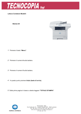
MANUALE D’ISTRUZIONI PER UNA CORRETTA INSTALLAZIONE DEI MOTORI TUBOLARI INSTRUCTION MANUAL FOR A CORRECT INSTALLATION OF TUBULAR MOTORS www.bruelmotion.com INDICE SICUREZZA………………………………………………………………………………………………………………………………..... 2 NOTE…………………………………………………………………………………………………………………….....……………….... 2 IL CODICE DEL MOTORE…………………………………………………………………………………………………….......…….. 3 ACCESSORI PER L’INSTALLAZIONE…………………………………………………………..........….………………………… 3 ISTRUZIONI PER D’INSTALLAZIONE …………………………………….................................................................. 4 COLLEGAMENTI ELETTRICI…………………………………………………………………….......…………………………………. 5 MOTORI CON RICEVITORE INTERNO Mod. Proteo – Pulse E – ED-EV……………......………………………………….5 PROGRAMMAZIONE DEL TRASMETTITORE Mod. Proteo – Pulse E – ED-EV……………………………….……..…. 6 RESET DEL TRASMETTITORE Mod. Proteo – Pulse E – ED-EV….................................................................... 6 PROGRAMMAZIONE DI DUE TRASMETTITORI SU UN MOTORE Mod. Proteo – Pulse E – ED - EV.................. 7 PROGRAMMAZIONE DI UN TRASMETTITORE CON PIU’ MOTORI Mod. Proteo – Pulse E – ED - EV............... 7 PROGRAMMAZIONE DEL FINECORSA Mod. Pulse E – ED …..…………………………………….…………………………. 7 PROGRAMMAZIONE DEL FINECORSA Mod.Pulse EV …..…………………………………….………………………….……8 REGOLAZIONE DEL FINECORSA Mod. Ecologic – Proteo ………………………………...…………………………….…… 8 CENTRATURA FINECORSA Mod. Ecologic – Proteo …………………………..……………………………………...…..…… 8 REGOLAZIONE TRAMITE PULSANTE SULLA TESTA Mod. Easy …………………………………………………...………… 9 REGOLAZIONE TRAMITE PROGRAMMATORE ……………………..…………………………………………...…………….… 10 PROBLEMI E SOLUZIONI………………………………………………………………………………………………………………...10 ---------SICUREZZA IMPORTANTE: Per garantire la sicurezza è necessario effettuare una corretta installazione, quindi è importante attenersi alle seguenti istruzioni e conservarle: 1. I parametri elettrici riportati in targa non devono essere superati in condizioni di carico. 2. L’alimentazione elettrica deve essere fornita con circuito protetto da dispositivo di interruzione automatica opportunamente coordinato con l’impianto di messa a terra. 3. Il cavo di terra del motore deve sempre essere collegato all’impianto di messa a terra dell’edificio. 4. I cavi non devono entrare in contatto con parti in movimento. Tutti i collegamenti devono essere eseguiti da personale competente. 5. Installare i sistemi di controllo ad una altezza minima di 1,5 metri da terra. 6. Mantenere i sistemi di comando e di controllo lontano dalla portata dei bambini. 7. I sistemi di comando devono essere installati ed utilizzati in posizione da cui sia visibile l’apparato in movimento 8. Verificare periodicamente la funzionalità del sistema e che non si presentino eventuali segni di usura sui cavi o sulle parti meccaniche. Verificare inoltre il bilanciamento dell’apparato in movimento 9. La corretta installazione e taratura del sistema sono responsabilità dell’installatore, che quindi dovrà essere “personale specializzato”. NOTE Se si desidera movimentare manualmente un motore, installare un motore di tipo S (con manovra di soccorso) avvalendosi di un installatore professionista per l’allineamento del sistema anello-asta, altrimenti difficoltoso. La funzione manuale viene esclusa automaticamente quando il motore è azionato elettricamente. Durante l’utilizzo in modalità manuale non insistere nell’azionamento quando il motore ha raggiunto i limiti di corsa preimpostati, ciò per evitare danneggiamenti alla struttura ed ai fine corsa stessi. 2 IL CODICE DEL MOTORE DIAMETRO MOTORE : 25 – 35 – 45 – 59 – 92 mm VELOCITA’ : A= fino a 14 RPM C= da 20 a 29 RPM B= da 15 a 19 RPM D= oltre 30 RPM TIPO MOTORE : ECO LOGIC serie N – Elettromeccanico con fine corsa meccanico ECO LOGIC serie S – Elettromeccanico con fine corsa meccanico + manovra di soccorso EASY serie B – Elettromeccanico con fine corsa elettronico PROTEO serie C – Elettromeccanico radiocomandato con fine corsa meccanico PULSE serie E – Controllo elettronico con fine corsa elettronico PROTEO serie CS – Elettromeccanico radiocomandato con fine corsa meccanico + manovra di soccorso PULSE serie ED – Controllo elettronico con fine corsa elettronico + pretensionamento del telo (tenda da sole) PULSE serie EV – Controllo elettronico con tre fine corsa a controllo elettronico ECO LOGIC serie DC – Elettromeccanico con fine corsa meccanico corrente continua ECO LOGIC serie NQ – Elettromeccanico con fine corsa meccanico Supersilenzioso PROTEO serie CQ – Elettromeccanico radiocomandato con fine corsa meccanico super silenzioso ACCESSORI PER L’INSTALLAZIONE Scala Trapano Chiave inglese Pinze o forbice elettricista Metro Seghetto per ferro Cacciavite a taglio e a stella Set brugole Lubrificante per cuscinetti Livella 3 ISTRUZIONI D’INSTALLAZIONE Nota: Prima di installare il motore è possibile verificare la posizione della corona per la regolazione dei fine corsa in modo da eseguire una preimpostazione nel caso di installazioni particolari (vedi istruzioni di pag. 9) 1. Montare l’adattatore (5) sul motore (3) e al fine di stabilire la posizione dell’adattatore all’interno del rullo, misurare la distanza tra adattatore e corona (4). Quindi inserire il tutto nel rullo (2). La corona (4) si troverà sul lato del rullo attraverso il quale è stato inserito il motore. 2. Utilizzare le apposite molle per fissare l’avvolgibile sul rullo (fig.7). ATTENZIONE: NON FORARE il rullo e non usare viti per fissare l’avvolgibile! C’è il rischio di danneggiare il motore se si creano contatti tra viti di fissaggio e il motore stesso (figg.7 – 8). 3. Inserire la calotta fissa o regolabile sul tubo e fissare con viti (fig.9) 4 4. Applicare la staffa al motore e quindi fissare il sistema rullo/motore alla parete/zanca. COLLEGAMENTI ELETTRICI Collegare i cavi come indicato nello schema (10) per il motore elettromeccanico e come indicato nello schema (11) per il motore elettronico e con ricevitore interno. Motore elettromeccanico Motore elettronico con ricevitore interno NOTA: Tutti i motori elettromeccanici ( fig. 10 ) non devono mai essere collegati in parallelo Il senso di rotazione orario e antiorario si determina guardando il motore dalla parte dell’uscita dell’albero MOTORI CON RICEVITORE INTERNO Mod. Proteo – Pulse E-ED-EV NOTA: Il motore viene fornito con il trasmettitore già programmato. 5 PROGRAMMAZIONE DEL TRASMETTITORE Mod. Proteo – Pulse E-ED-EV ATTENZIONE: Tenere presente che devono trascorrere meno di 10 sec tra una operazione e la successiva altrimenti il motore esce dallo stato di programmazione e sarà necessario ripetere l’intera procedura. 1.1. Attivare l’alimentazione del motore. Il motore è pronto per la programmazione. 1.2. Premere 2 volte il tasto di SETTAGGIO, poi premere il tasto GIU’, a questo punto il trasmettitore è programmato. 1.3. Verificare che il senso di rotazione sia corretto. Se non è corretto eseguire i passi 1.4 e 1.5 per invertire il senso di rotazione sul trasmettitore. 1.4. Disattivare e riattivare l’alimentazione del motore. Il motore è pronto per la programmazione. 1.5. Premere 2 volte il tasto di SETTAGGIO, poi premere il tasto SU, a questo punto il trasmettitore è programmato nel nuovo senso di rotazione NOTA: Per il modello EV premere il tasto sulla testa per entrare in programmazione. RESET DEL TRASMETTITORE Mod. Proteo – Pulse E-ED-EV Premere il tasto di SETTAGGIO, poi il tasto STOP e di nuovo il tasto di SETTAGGIO; il trasmettitore è resettato e pronto per una nuova programmazione. NOTA: Ogni volta che si vuole riprogrammare il trasmettitore occorre disattivare e poi riattivare l’alimentazione del motore. 6 PROGRAMMAZIONE DI DUE TRASMETTITORI CON UN MOTORE Mod. Proteo – Pulse E-ED-EV 1. Prendere il trasmettitore A (precedentemente programmato sul motore), premere 2 volte il tasto SETTAGGIO. Subito dopo premere il tasto SETTAGGIO del trasmettitore B; a questo punto anche il trasmettitore B sarà programmato con la stessa frequenza Per il trasmettitore multicanale, prima posizionarsi sul canale desiderato (es. 1-2-3- etc.) poi eseguire la stessa programmazione del punto 1.Il numero 0 o l’accensione di tutti i led sul trasmettitore esegue il movimento contemporaneo di tutti i motori NOTA: Ogni volta che viene effettuata una modifica su uno dei due trasmettitori, anche l’altro viene modificato automaticamente (p.e.: inversione del senso di rotazione o reset completo del trasmettitore). PROGRAMMAZIONE DI UN TRASMETTITORE CON PIU’ MOTORI Mod. Proteo – Pulse E-ED-EV Per poter programmare 1 trasmettitore per 2 o più motori occorre alimentarne uno alla volta, verificando che il senso di rotazione sia corretto. Procedere come segue: 4.1 Alimentare il motore 1 e procedere alla programmazione come da punto 1.) 4.2 Togliere l’alimentazione al motore 1. 4.3 Alimentare il motore 2 e procedere alla programmazione come da punto 1.) Per programmare ulteriori motori, ricordarsi di togliere l’alimentazione ai motori precedentemente programmati. Concluse tutte le programmazioni è possibile riattivare l’alimentazione di tutti i motori programmati. ATTENZIONE: Nel caso si debba effettuare una modifica della programmazione su un solo motore, togliere l’alimentazione agli altri motori del gruppo. NOTA: Per il modello EV basta alimentare tutti i motori e si esegue la programmazione, uno alla volta, premendo il tasto sulla testa. NOTA: Se si programma un gruppo di motori per essere azionati da un solo trasmettitore, non è possibile inserire un secondo trasmettitore per azionare un motore singolarmente. Perché su quel motore si annullerebbe la programmazione del primo trasmettitore, che gestisce il gruppo. PROGRAMMAZIONE DEL FINECORSA Mod. Pulse E 1. Premere il tasto di SETTAGGIO, poi premere il tasto SU e di nuovo il tasto SETTAGGIO, si vedrà un breve movimento in senso orario e antiorario. 7 2. Premere il tasto SU, il motore inizia a girare. Appena vicini al limite desiderato, premere SETTAGGIO, il motore continua il movimento con brevi scatti, in modo da eseguire una regolazione millimetrica. Appena raggiunta la posizione desiderata premere STOP, quindi ripremere il tasto STOP per cinque secondi, fino all’avvenuta conferma, tramite un breve movimento in senso orario ed antiorario, del motore. Premere il tasto GIU’, il motore inizia a girare, appena vicini al limite desiderato premere SETTAGGIO, il motore continua il movimento con brevi scatti, in modo da eseguire una regolazione millimetrica. Appena raggiunta la posizione desiderata premere STOP, quindi ripremere il tasto STOP per cinque secondi, fino all’avvenuta conferma, tramite un breve movimento in senso orario ed antiorario, del motore. PROGRAMMAZIONE DEL FINECORSA Mod. Pulse ED 1. Premere il tasto di SETTAGGIO, poi premere il tasto SU e di nuovo il tasto SETTAGGIO, si vedrà un breve movimento in senso orario e antiorario. 2. Premere il tasto GIU’ il motore inizia a girare. Appena raggiunta la posizione desiderata premere STOP. Quindi ripremere il tastoSTOP per cinque secondi fino all’avvenuta conferma tramite un breve movimento in senso orario ed antiorario del motore. Premere il tasto SU il motore inizia a girare, quindi far arrivare la tenda in battuta per fargli memorizzare il fine corsa, a questo punto la programmazione è conclusa. PROGRAMMAZIONE DEL FINECORSA Mod. Pulse EV Alimentare il motore, quindi premere il pulsante posto sulla testa, ha questo punto è pronto per la programmazione. 1. Premere il tasto di P2, poi premere il tasto SU e di nuovo il tasto P2, si vedrà un breve movimento in senso orario e antiorario. 2. Premere il tasto SU, il motore inizia a girare. Appena raggiunta la posizione desiderata, poi premere il tasto P2 per fare una regolazione fine, poi premere STOP appena raggiunta la posizione desiderata. Quindi ripremere il tasto stop per cinque secondi fino all’avvenuta conferma tramite un breve movimento in senso orario ed antiorario del motore. Premere il tasto GIU per fare la regolazione DELLE LAMELLE ORIENTABILI’ il motore inizia a girare, appena raggiunta la posizione desiderata, poi premere il tasto P2 per fare una regolazione fine, poi premere il tasto STOP appena raggiunta la posizione desiderata Quindi ripremere il tasto STOP per cinque secondi fino all’avvenuta conferma tramite un breve movimento. Ora con il tasto salita andare in posizione di chiusura totale, una volta fermata tenere il tasto STOP per cinque secondi fino all’avvenuta conferma tramite un breve movimento. In senso orario ed antiorario. 8 NOTA: UNA VOLTA PROGRAMMATO IL TASTO SU APRE, IL TASTO GIU’ ESEGUE L’ORIENTAMENTO DELLE LAMELLE E IL TASTO STOP PREMUTO PER CINQUE SECONDI ESEGUE LA CHIUSURA TOTALE SENZA AVER LA POSSIBILTA’ DI FERMARLO. REGOLAZIONE FINE CORSA Mod. Ecologic - Proteo 1.1 La procedura andrà avviata avendo cura che il telo oscurante sia completamente srotolato dal rullo. 1.2 Azionare l’avvolgibile nella direzione di salita e regolare il fine corsa agendo sulla vite con la freccia che indica il senso di direzione del telo oscurante (vedi nota) 1.3 Azionare l’avvolgibile nella direzione di discesa e regolare il fine corsa agendo sulla vite opposta (vedi nota) NOTA (Ruotando verso il segno - riduce la corsa del telo oscurante, verso il segno + aumenta la corsa del telo oscurante) CENTRATURA FINECORSA ATTENZIONE: In caso di anomalie nella regolazione dei fine-corsa, è probabile che si sia verificato uno dei seguenti casi: a. la procedura di installazione non è stata eseguita in modo corretto; b. la corona o le viti di regolazione sono state mosse manualmente prima dell’installazione; c. posizionato il motore nel rullo lo si è azionato a vuoto per un certo numero di giri, senza poi riportarlo nella posizione originale. Per rimettere il motore in condizioni normali di lavoro e quindi eseguire l’installazione, occorre procedere come segue: 1. togliere il motore dal tubo, in modo che meccanicamente risulti libero, 2. ruotare il fine-corsa ROSSO completamente verso il segno – (vedi nota), 3. ruotare il fine-corsa BIANCO completamente verso il segno + (vedi nota), 4. ruotare manualmente la corona che aziona i finecorsa per 10-12 giri in senso antiorario tenendo la testa del motore verso di sé. NOTA: eseguire l’operazione in luogo silenzioso in modo da sentire il rumore degli interruttori quando giungono a fine corsa. Attenzione: quando si arriva in fondo alla regolazione, le viti colorate (bianco e rosso) oppongono maggiore resistenza. Non sforzare le viti di regolazione o la corona onde evitare danneggiamenti. REGOLAZIONE TRAMITE PULSANTE SULLA TESTA Mod. Easy Pulsante programmazione 1. Alimentare il motore e azionare l’avvolgibile nella direzione di salita. 2. All’arrivo della posizione desiderata premere una volta il tasto verde. Il fine corsa è programmato 9 3. Se l’avvolgibile si ferma prima del raggiungimento della posizione desiderata, con motore alimentato premere e tenere premuto il pulsante verde fino alla posizione desiderata e poi rilasciare. 4. Se l’avvolgibile non si ferma al raggiungimento della posizione desiderata, occorre farlo tornare alla posizione di partenza ed eseguire nuovamente la procedura dal punto (1). 5. Azionare l’avvolgibile nella direzione discesa e seguire i punti 2 – 3 – 4. REGOLAZIONE TRAMITE PROGRAMMATORE Tasto comando Pulsanti programmazione 1. Collegare il programmatore sul cavo di alimentazione come in figura. 2. Alimentare il motore e azionare l’avvolgibile nella direzione di salita. 3. All’arrivo della posizione desiderata premere una volta il tasto verde. Il fine corsa è programmato. 4. Se l’avvolgibile si ferma prima del raggiungimento della posizione desiderata, con motore alimentato premere il pulsante verde fino alla posizione desiderata e poi rilasciare. 5. Se l’avvolgibile non si ferma al raggiungimento della posizione desiderata, occorre farlo tornare alla posizione di partenza ed eseguire nuovamente la procedura dal punto (2) 6. Azionare l’avvolgibile nella direzione discesa e seguire i punti 3 – 4 – 5. NOTA Il cavo bianco viene collegato solo al programmatore nel momento della programmazione dei fine corsa PROBLEMI E SOLUZIONI Problema Possibile causa Soluzione suggerita Azionando la funzione di salita, Motore elettromeccanico: Invertire i cavi elettrici nero e marrone. l’avvolgibile si muove in discesa e cavi elettrici non collegati viceversa. correttamente. Motore radiocomandato: Ripetere la procedura “Programmazione programmazione non corretta del del radiocomando” (pag. 10 e 11). radiocomando L’albero del motore gira solo in una La corona è ruotata fino al limite del Ruotare la corona nella direzione verso direzione fine-corsa relativo alla direzione cui può ruotare l’albero motore. (nota: si può verificare solo sul opposta a quella in cui ruota l’albero motore elettromeccanico). motore. Quando viene alimentato, il motore Motore elettromeccanico e non parte o gira lentamente. radiocomandato: a. tensione bassa b. errore nel collegamento dei cavi c. sovraccarico d. errore di installazione a. verificare la presenza di tensione di alimentazione sui morsetti del motore. b. verificare che i collegamenti elettrici siano stati eseguiti correttamente c. verificare che la coppia del motore sia adeguata al carico applicato d. controllare che l’installazione sia stata effettuata a regola d’arte Fermo improvviso del motore. Superati 4 minuti di funzionamento Attendere che il motore si raffreddi (in continuo è intervenuta la protezione condizioni critiche anche 20 minuti). termica. Il motore elettromeccanico si ferma e Le viti del fine-corsa non sono più Rimuovere il motore ed eseguire la non si riesce a regolare il fine-corsa centrate. centratura del fine-corsa seguendo la nella posizione voluta procedura di pag. 8. Il motore non parte quando si preme Motore radiocomandato: il pulsante di salita o discesa sul Batteria del radiocomando scarica. Sostituire la batteria. radiocomando. 10 INDEX SAFETY ……………………………………………………………………………………………………………………..…………….... 11 NOTES ……..…….…………………………………………………………………………………………………….....……………..... 11 THE MOTOR CODE …………….……………………………………………………………………………………………….......….. 12 ACCESSORIES FOR INSTALLATION …..………………………………………………………..........….……………………… 12 INSTALLATION INSTRUCTION …...……………………………………….................................................................13 WIRING CONNECTION ………….……………………………………………………………….......……………………………… 14 RADIO MOTORS Mod. Proteo – Pulse E – ED - EV………………………………….…......…………………………………. 15 TRANSMITTER SETUP Mod. Proteo – Pulse E – ED - EV………………………………………….……………….……..…. 15 RESET OF TRANSMITTER Mod. Proteo – Pulse E – ED –EV …….….............................................................. 16 SETUP OF TWO TRANSMITTERS WITH ONE MOTOR Mod. Proteo – Pulse E – ED – EV ............................... 16 SETUP OF ONE TRANSMITTER WITH MORE THAN ONE MOTOR Mod. Proteo – Pulse E – ED – EV .............. 16 LIMIT SWITCH SETUP Mod. Pulse E – ED …..………………………….…………………………….……………………….. 17 LIMIT SWITCH SETUP Mod. Pulse EV ………………………………...................…………………………….……………. 18 LIMIT SWITCH SETUP Mod. Ecologic – Proteo ………….............................................................................. 18 LIMIT GEARS CENTERING Mod. Ecologic – Proteo …………………………..……………………………………...…..…. 19 SETUP BY HEAD-BUTTON Mod. Easy ……..………………………………………………………………………………………. 19 SETUP BY PROGRAMMER ……..……………………………………………………………………………………………………… 19 TROUBLES AND SOLUTIONS ……..………………………………………………………………………………………………….. 20 ---------- SAFETY IMPORTANT: To grant a safe use, an appropriate installation is mandatory. It is important to follow these instructions and to keep them for future reference. 1. Do NOT exceed the max load of the motor. 2. The electrical power line must be protected by a differential switch. 3. The ground cable of the motor must always be connected to the building ground circuit. 4. All cables must be safe from moving parts. Electrical connections must be executed by properly trained people. 5. It is suggested to install control systems at min. 1,5 meters height. 6. Don’t let children play with control systems. 7. All control systems must be installed in a place where moving system is visible. 8. Verify periodically that the system works properly and that cables and mechanical parts don’t show wear and tear. Verify also that the mechanical system is balanced. 9. Installation and adjustment must be executed by properly trained people. NOTES If manual operations are required, motor model S is mandatory (manual motor). The handling must be installed and aligned by trained people, since it would be a difficult operation for unskilled people. 11 The manual function is automatically disabled when electrical power is applied to the motor. When the motor is in manual mode, don’t force the limits in order to avoid damaging the system and the limit switches. THE MOTOR CODE MOTOR DIAMETER: 25 – 35 – 45 – 59 – 92 mm SPEED: A= up to 14 Rpm C= from 20 to 29 Rpm B= from 15 to 19 Rpm D= over 30 Rpm MOTOR TYPE: ECO LOGIC series N – Electromechanical with mechanical limit switch ECO LOGIC series S – Electromechanical with mechanical limit + manual EASY series B – Electromechanical with electronic limit switch PROTEO series C – Electromechanical remote control with mechanical limit switch PULSE series E – Electronic control with electronic limit switch PROTEO series CS – Electromechanical remote control with mechanical limit switch + limit PULSE series ED – Electronic control with electronic limit switch + tension of awning PULSE series EV – Electronic control with three electronic limit switches ECO LOGIC series DC – Electromechanical with mechanical limit switch DC ECO LOGIC series NQ - Electromechanical with quiet mechanical limit switch PROTEO series CQ - Electromechanical remote control with quiet mechanical limit switch ACCESSORIES FOR INSTALLATION Ladder Drill Monkey spanner Princers or wire stripper Meter Hacksaw Screwdriver Socket head screw Lubrificant for ball bearings Level 12 INSTALLATION INSTRUCTION Before installing the motor, it is possible to verify the crown position to adjust the limit switch. For particular installations, it is possible to pre-adjust the position to allow a better fitting of the installation (see instructions on p. 9). 1. Install the drive adaptor (5) on the motor (3) and in order to determine where the adaptor will be positioned inside the roller tube, measure the distance between the adaptor and the crown (4). Finally, insert them into the roller tube (2). The crown (4) will be on the tube side where the motors has been inserted. 2. Use the clamp springs in order to fix the rolling system on the roller tube (7). ATTENTION: don’t make screw holes to fix the rolling system because there is the risk to put in contact motor and fixing screws. (7 – 8). 13 3. Insert the pinion idler and fix it using screws (9) 4. Install the bracket on the motor and then fix the roll/motor system on the wall/bracket. WIRING CONNECTION Connect the wires as indicated in the wiring diagram (10) for standard motor and as indicated in the wiring diagram (11) for radio and electronic motor. Standard motor Radio motor NOTE: All electromechanical motors (fig. 10) must never be connected in parallel The direction of rotation: CCW and CW is determined by looking the motor from the output side of the shaft. 14 RADIO MOTORS Mod. Proteo – Pulse E-ED-EV NOTE: The motor has the transmitter already configured. TRANSMITTER SETUP Mod. Proteo – Pulse E-ED-EV ATTENTION: Pay attention: no more than 10 sec. can elapse between one operation and the other. If more than 10 sec. elapse, the setup will not be completed and it will be necessary to repeat the whole procedure. 1.1. Turn on the power of the motor. The motor is ready for setting. 1.2. Push 2 times the setup button, then push the down button. The transmitter is programmed. 1.3. Verify that the direction of rotation is correct. If it is not correct, please follow the next points 1.4 and 1.5 to reverse the direction of rotation on the transmitter. 1.4. Cut off and then reconnect the motor’s power supply. The motor is ready for setting. 1.5. Push 2 times the setup button, then push the up button. The transmitter is now programmed with the new direction of rotation. NOTE: For the EV model push the button on the head of to start setting. 15 RESET OF TRANSMITTER Mod. Proteo – Pulse E-ED-EV Push the setup button, then the stop button and again the setup button. The transmitter is now reset and ready for a new setup. NOTE: Whenever the transmitter must be reset, it is necessary to power off and then power again the motor. SETUP OF TWO TRANSMITTERS WITH ONE MOTOR Mod. Proteo – Pulse E-ED-EV Take the transmitter A (previously programmed with the motor) and push twice the setup button. After push the setup button of transmitter B. Transmitter B has now been programmed on the same frequency. For the multi-channel transmitter: first select the desired channel (for ex.: 1-2-3 etc.) then run the same programming of point 1. The number 0 or all led lighted on the transmitter run the simultaneous movement of all motors. NOTE: Whenever a modification is effected on one of the two transmitters, also the other one will be modified automatically (for i.e.: inversion of direction of rotation or complete reset of the transmitter). SETUP OF ONE TRANSMITTER WITH MORE THAN ONE MOTOR Mod. Proteo – Pulse E-ED-EV In order to program one transmitter for two or more motors, it is necessary to power one motor at a time, verifying that the direction of rotation is correct. Please proceed as follows: 4.1 Power motor 1 and then proceed with the setup according to point no. 1.) 4.2 Power off motor 1. 4.3 Power motor 2 and proceed with the setup according to point 1.) In order to program other motors, please don’t forget to power off the motors previously set up. Once all the settings have been completed, it is possible to power all the set up motors. 16 ATTENTION: In case you need to modify the setup of only one motor, please power off the other motors. NOTE: For EV model – simply power all motors and then effect the setup (a motor at a time), pressing the button on the head. If a group of motors has been programmed in order to be operated with one transmitter, it is not possible to add a second transmitter to operate a single motor. Because on that motor the setup of the first transmitter would be lost. LIMIT SWITCH SETUP Mod. Pulse E 1. Push the setup button, then the up button and again the setup button. You will note a short CC and CCW move. 2. Push the up button and the motor starts to move. When it reaches the desired limit, push the setup button. The motor continues to move with short shots so that it can reach a millimeter regulation, as soon as it reaches the desired limit, push the stop button. Then push again the stop button for five seconds till it is set by a CC and CCW move. Push the down button and the motor starts to move. When it reaches the desired limit push the setup button. The motor continues to move with short shots so that it can reach a millimeter regulation, as soon as it reaches the desired limit you have to push the stop button. Then push again the stop button for five seconds till it is set by a CC and CCW move. LIMIT SWITCH SETUP Mod. pulse ED 1. Push the setup button, then the up button and again the setup button. You will note a short CC and CCW move. 2. Push the down button and the motor starts to move as it reaches the desired limit push the stop button. Then push again the stop button for five seconds till it is set by a CC and CCW move. Push the up button and the motor starts to move. Then the awning has to reach the fine joke to store the limit switch. The programming is finished. 17 LIMIT SWITCH SETUP Mod. Pulse EV Feed the motor then push the button on the head. Now the motor is ready for setup. 1. Push the button P2 then push the button up and again the button P2. You will note a short CC and CCW move. 2. Push the up button and the motor starts to move. As it reaches the desired limit push the button P2 (so that it can reach a millimeter regulation). Then push the stop button when the motor reaches the desired position. Then push again the stop button for five seconds till it is set by a CC and CCW move. Push the down button to effect the regulation of the adjustable louvres. The motor starts to move. As it reaches the desired limit push the button P2 (so that it can reach a millimeter regulation). Then push the stop button when the motor reaches the desired position. Then push again the stop button for five seconds till it is set by a short move. Now with the the up button go to the closed total position. Once reached the position, push the stop button for five seconds till it is set by a short CC and CCW move. NOTE: Once the programming has been complete: up button = open down button = turn louvres stop button = pressing it for five seconds it will go to the closed total position without having the possibility to stop it. LIMIT SWITCH SETUP Mod. Ecologic - Proteo 1.1 The programming has to be done with a completely unwound blackout sheet from the roller tube. 1.2 Move the rolling system in rise direction and adjust the limit switch working on the screw with the arrow, which shows the sense of rotation of the blackout sheet (see note below). 1.3 Move the rolling system in down direction and adjust the limit switch on the opposite screw (see note below). NOTE (Turning towards “– sign” you reduce the stroke of the blackout sheet. While turning towards “+ sign” you increase the stroke of the blackout sheet). 18 LIMIT GEARS CENTERING ATTENTION: In case of anomalous regulation of the limit switch, probably one of the following cases has occurred: a. the installation has not been performed in the proper way, b. the limit switch crown or the limit switch screws have been moved manually before installation, c. Once the motor has been positioned into the rolling tube, it probably has been operated at no load for a certain number of turns, without resetting the original position. To reset the normal position and proceed with the correct regulation, please follow these procedure: 1. take the motor out of the roller tube to operate on it 2. turn completely the RED limit toward the - sign (read note) 3. turn completely the WHITE limit toward the + sign (read note) 4. rotate manually the limit switch crown for at least 10-12 turns CCW, keeping the motor head towards you. NOTE: make this operation in a quiet place in order to hear the switch noise when it reaches the limit. Warning: when the regulation gear is at the bottom, the coloured screws (white and red) become stiffer. To avoid undesired damages, please don’t force regulation screws and crown. SETUP BY HEAD-BUTTON Mod. Easy Setup button 1. Power the motor and move the rolling system in rise direction. 2. When it reaches the desired position push one time the green button. The limit switch is programmed. 3. If the rolling system stops before reaching the desired position (with powered motor), push and hold the green button till it reaches the desired position and then release it. 4. If the rollling system doesn’t stop when it reaches the desired position, return it to the starting position and start again the procedure from the point 1. 5. Move the rolling system in down direction and follow points 2 – 3 - 4 SETUP BY PROGRAMMER Control button Programming buttons 1. Connect the programmer on the control button (see the picture above). 2. Power the motor and move the rolling system in rise direction. 3. When it reaches the desired position push one time the green button. The limit switch is programmed. 4. If the rolling system stops before reaching the desired position (with powered motor), push and hold the green button till it reaches the desired position and then release it. 5. If the rollling system doesn’t stop when it reaches the desired position, return it to the starting position and start again the procedure from the point 2. 6. Move the rolling system in down direction and follow points 3 – 4 – 5 NOTE The white cable is connected only to the programmer when you setup the limit switch. 19 TROUBLES AND SOLUTIONS Trouble Possible reason Suggested solution The motor moves in the wrong Standard motor: Invert the black and brown direction. Wrong electrical wiring electrical wires. connection. Radio motor: Repeat the procedure “remote Incorrect programming of the control setup” (pages. 10, 11). remote control. The shaft moves only in one The limit switch of the blocked Rotate the crown in the direction (can occur only on the direction is off. opposite direction to the desired standard motor). direction of rotation. When electrical power is applied Standard and radio motor: the motor moves slowly or it a. low voltage doesn’t move. b. wrong wires connection c. overload d. wrong installation a. verify that the motor is supplied at the rated voltage b. check the electrical wires connections c. verify that the installed motor has appropriate torque d. Verify that the installation has been performed properly Sudden stop of the operating The rated continuous working Wait that the motor cools down motor. time (4 minutes) have been (in critical cases it can take exceeded. even 20 minutes) The standard motor stops The limit switch screws are not Remove the motor and follow operating and limit switch cannot centered. the procedure of limit switch be regulated as desired. regulation (page 8). The motor doesn’t move when Radio motor: push the up button or down the remote control’s battery is button of the remote control. low. Replace battery with a new one. 20
Scarica