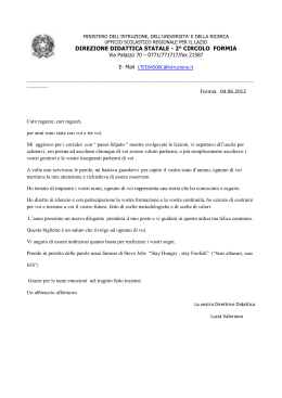
USO E MANUTENZIONE Istruzioni di montaggio E n itio d e/E on dizi B r I-G Septembe USE AND MAINTENANCE / bre 2 201 tem Set Instruction manual RMEJ MOTORIZZAZIONE ELETTRICA UNIVERSALE PER AVVOLGIFIOCCO MANUALE UNIVERSAL ELECTRIC MOTORIZATION TO RETROFIT EXISTING FURLERS 1.02 2.02 3.02 4.02 I INDICE GENERALE GENERAL INDEX a INFORMAZIONI GENERALI.............................4 Introduzione.......................................................4 A-1 Simbologia presente nel manuale......................5 A-2Assistenza..........................................................5 A-3 Dati di identificazione.........................................6 A-3.1 Modello e tipo.....................................................6 A-3.2 Costruttore.........................................................6 A-3.3 Targhetta di identificazione.................................6 A-4 Imballo e contenuto............................................7 A-5 Ricevimento del materiale..................................7 A-6 Attrezzatura minima necessaria.........................8 A-7 Norme applicate.................................................8 A-8 Descrizione dell’apparecchiatura.......................8 A-9 Dati tecnici..........................................................9 A-9.1 Dati tecnici per modelli.....................................10 A-9.2 Perni per landa................................................. 11 A-10 Impieghi ammessi............................................ 11 A-11 Uso improprio................................................... 11 A GENERAL INFORMATION................................4 Introduction........................................................4 A-1 Symbols to be found in the manual....................5 A-2 After-sales service..............................................5 A-3 Identification data...............................................6 A-3.1 Model and type...................................................6 A-3.2Manufacturer......................................................6 A-3.3 Identification plate..............................................6 A-4 Packaging and content.......................................7 A-5 Receipt of goods................................................7 A-6 Basic tools..........................................................8 A-7 Rules to be applied............................................8 A-8 Description of the equipment.............................8 A-9 Technical data....................................................9 A-9.1 Technical data by model...................................10 A-9.2 Clevis pins........................................................ 11 A-10 Proper use........................................................ 11 A-11 Wrong use........................................................ 11 BSICUREZZA.....................................................12 B-1 Indicazioni generali..........................................12 BSAFETY...........................................................12 B-1 General indications..........................................12 Cistruzioni di montaggio.........................13 C-1 Operazioni preliminari......................................13 C-1.1 Determinazione del tipo di strallo interno.........13 C-1.2 Determinazione della lunghezza dello strallo interno....................................................14 C-1.3 Accessori per lo strallo in fune (opzionali).............. 15 C-1.4 Landa di prua...................................................16 C-2 Determinazione della lunghezza lande............17 C-2.1 Determinazione del punto ove tagliare il profilo esistente.............................................17 C-3 Preparazione al montaggio..............................18 C-3.1 Taglio a misura del profilo................................18 C-4 Montaggio della boccola di adattamento sulla motorizzazione.........................................20 C-4.1 Montaggio dell’adattatore sul profilo inferitore.20 C-5 Montaggio dell’avvolgifiocco in testa d’albero..21 C-6 Regolazione del tenditore dello strallo.............21 C-7 Fissaggio del motoriduttore RMEJ per mezzo delle lande........................................................22 C-8 Montaggio dell’avvolgifiocco con albero armato...................................................22 C-9 Collegamento elettrico.....................................23 C-10 Emergenza manuale........................................24 C-11 Consigli per la vela...........................................25 C-12 Montaggio della vela........................................26 C-13 Uso dell’avvolgifiocco.......................................26 Cinstallation...............................................13 C-1 Preliminary operations.....................................13 C-1.1 Determining what type of stay is fitted.............13 C-1.2 Determining the stay length.............................14 C-1.3 Wire stay accessories (optional)......................15 C-1.4 Chain plate.......................................................16 C-2 How to determine the length of link plates.......17 C-2.1 How to determine the point where to cut the existing foil.......................................................17 C-3 How to prepare the foils for the installation......18 C-3.1 How to cut the foil to measure..........................18 C-4 How to fit the tack adapter onto the motorization......................................................20 C-4.1 How to fit the tack adapter onto the hoisting foil.......................................................20 C-5 How to install the furler onboard......................21 C-6 How to adjust the turnbuckle............................21 C-7 How to install the rmej motorization by means of its link plates.....................................22 C-8 How to install the furler on armed mast............22 C-9 Electric connection...........................................23 C-10 Manual emergency clutch................................24 C-11 Suggestions for the sail....................................25 C-12 How to hoist the sail.........................................26 C-13 How to use the furler........................................26 DMANUTENZIoNE............................................27 D-1Manutenzione...................................................27 D-1.1 Brevi periodi di inutilizzo...................................27 D-1.2 Lunghi periodi di inutilizzo................................27 D-2 Sostituzione della cinghia di trasmissione........28 D-2.1Occorrente.......................................................28 D-2.2Procedimento...................................................28 D-2.3 Regolazione della tensione della cinghia.........29 D-3 Come rimpiazzare la puleggia condotta...........29 D-3.1 Apertura coperchio ..........................................29 DMAINTENANCE...............................................27 D-1Maintenance.....................................................27 D-1.1 Short inactivity..................................................27 D-1.2 Long inactivity..................................................27 D-2 How to replace the drive belt............................28 D-2.1 Required tools .................................................28 D-2.2Procedure.........................................................28 D-2.3 How to tension the drive belt............................29 D-3 How to replace the main drive belt sheave......29 D-3.1 How to open the cover ....................................29 2 UM_RMEJ_I-GB_rev. 2.0 I INDICE GENERALE GENERAL INDEX D-3.2 D-3.3 D-3.4 D-3.5 D-4 D-5 Togliere la puleggia condotta ..........................30 Montaggio nuova puleggia ..............................31 Montaggio eccentrico.......................................31 Operazioni finali ..............................................32 Sostituzione del motore elettrico......................34 Inconvenienti - cause - rimedi..........................37 D-3.2 How to remove the main drive belt sheave ......30 D-3.3 How to fit the new sheave ................................. 31 D-3.4 How to put the eccentric pin into place............31 D-3.5 Final steps........................................................32 D-4 How to replace the electric motor.....................34 D-5Troubleshooting................................................37 e E-1 E-2 PARTI DI RICAMBIO.......................................38 Parti di ricambio motoriduttore RMEJ 1.02......38 Parti di ricambio motoriduttore RMEJ 2.02......40 e E-1 E-2 Spare parts................................................38 RMEJ 1.02 Motorization spare parts................38 RMEJ 2.02 Motorization spare parts................40 GARANZIA......................................................42 WARRANTY.....................................................42 © Copyright Zattini Group srl Tutti i diritti riservati Stampato in Italia Realizzazione: Zattini Group srl - Forlì © Copyright Zattini Group srl All rights reserved Printed in Italy Realization: Zattini Group srl - Forlì Questo manuale o parti di esso non possono essere riprodotti, copiati o divulgati con qualsiasi mezzo senza la preventiva autorizzazione scritta della ditta Zattini Group srl. La ditta Zattini Group srl si riserva il diritto di apportare in qualsiasi momento tutte le modifiche che riterrà opportune, nella costante ricerca di migliorare la qualità e la sicurezza delle attrezzature, senza impegnarsi ad aggiornare di volta in volta questa pubblicazione. UM_RMEJ_I-GB_rev. 2.0 No part of this manual may be reproduced, copied or transmitted in any form, or by any means without permission in writing from Zattini Group srl. Zattini Group srl has the right to make any changes they think necessary in order to improve the quality and safety of the systems, without being obliged to revise this publication every time. 3 A INFORMAZIONI GENERALI GENERAL INFORMATION Introduzione Introduction Questo manuale è stato realizzato allo scopo di fornire tutte le informazioni necessarie per installare ed utilizzare l’apparecchiatura in maniera corretta e sicura e per effettuarne la manutenzione. This manual has been realised in order to supply all required information for a correct and safe installation, use and maintenance of the equipment. Occorre leggere e capire questo manuale prima di usare l’apparecchiatura, ed effettuare qualsiasi operazione con esso o su di esso. You have to read and understand this manual before using the equipment and carrying out any operation on it. Il manuale è suddiviso in sezioni, capitoli e paragrafi in modo da presentare le informazioni strutturate in modo chiaro. Le pagine sono numerate progressivamente. La ricerca delle informazioni può essere basata sull’utilizzo delle parole chiave usate come titolo delle sezioni e dei capitoli ma soprattutto dalla consultazione dell’indice generale. This manual has been divided into sections, chapters and paragraphs in order to present the information in a structured and clear way. Pages are numbered progressively. The search for information may be done either through the key words used as titles for the sections, or through the consultation of the general index. Conservare questo manuale anche dopo la completa lettura, in modo che sia sempre a portata di mano per il chiarimento di eventuali dubbi. Keep this manual at hand even after having read it, it may help clarify any doubt. In caso di problemi nella comprensione di questo manuale o di parti di esso si raccomanda vivamente di contattare la ditta Zattini Group srl: indirizzi, numeri di telefono e telefax sono riportati nella quarta di copertina di questo manuale. Should you have problems in understanding this manual or parts of it, we strongly recommend contacting Zattini Group srl: address, phone and fax number can be found on the cover. La ditta Zattini Group srl declina ogni responsabilità per danni a persone o cose derivanti da un uso improprio dell’attrezzatura, da imperizia, imprudenza o negligenza e dalla inosservanza delle norme descritte in questo manuale. Zattini Group srl declines any and every responsibility for damages to persons or things caused by either an improper use of the system or inexperience, negligence, imprudence, or noncompliance with this manual. 4 UM_RMEJ_I-GB_rev. 2.0 A A-1 INFORMAZIONI GENERALI GENERAL INFORMATION Simbologia presente nel manuale In questo manuale sono utilizzati cinque tipi di “simboli grafici di sicurezza”, che hanno lo scopo di evidenziare altrettanti livelli di pericolo o informazione: A-1 Symbols to be found in the manual Five “graphic safety symbols” are used in this manual. Their purpose is to highlight different levels of danger and/ or information: PERICOLO Richiama l'attenzione a situazioni o problemi che potrebbero pregiudicare l'incolumità delle persone per PERICOLO infortuni o rischio di morte. PERICOLO DI FOLGORAZIONE DANGER Draws one’s attention to situations or problems that might endanger the safety of persons, causing the risk of accident DANGER and death. DANGER OF ELECTROCUTION PERICOLO PERICOLO DI FOLGORAZIONE Richiama l'attenzione ad una situazione di grave pericolo ATTENZIONE che potrebbe pregiudicare l'incolumità delle persone PERICOLO esposte fino a possibili rischi di morte dovuti alla presenza PERICOLO DI FOLGORAZIONE ATTENZIONE di tensione. PERICOLO AVVERTENZA PERICOLO DI FOLGORAZIONE ATTENZIONE AVVERTENZA Richiama l'attenzione situazioni o problemi connessi PERICOLO DI a FOLGORAZIONE RISPETTA L'AMBIENTE con l'efficienza della macchina che non pregiudicano la ATTENZIONE sicurezza delle persone. AVVERTENZA RISPETTA L'AMBIENTE ATTENZIONE AVVERTENZA Richiama l'attenzione a importanti informazioni di carattere RISPETTA L'AMBIENTE generaleAVVERTENZA che non pregiudicano né la sicurezza personale, né il buon funzionamento della macchina. RISPETTA L'AMBIENTE DANGER DANGER OF ELECTROCUTION Draws one’s attention to a highly dangerous situation that CAUTION might endanger the safety and life of exposed persons due DANGER to the presence of electricity. DANGER CAUTION OF ELECTROCUTION DANGER WARNING DANGER OF ELECTROCUTION CAUTION WARNING Draws one’s attention to situations or problems linked to DANGER OF ELECTROCUTION RESPECT THE ENVIRONMENT the system’s efficiency which do not endanger the safety CAUTION of people. WARNING RESPECT THE ENVIRONMENT CAUTION WARNING Draws one’s attention important general information RESPECT THEto ENVIRONMENT that endangers neither personal safety nor the operation WARNING of the system. RESPECT THE ENVIRONMENT RISPETTA L'AMBIENTE Per attirare l'attenzione verso importanti informazioni per il rispetto dell'ambiente. RESPECT THE ENVIRONMENT Draws one’s attention to important pieces of information concerning respect for the environment. A-2Assistenza A-2 Qualora ci siano dubbi sull’utilizzo o la manutenzione dell’apparecchiatura, consigliamo di contattare la ditta Zattini Group srl. Should you have any doubt concerning either the use or maintenance of the equipment, we suggest contacting Zattini Group srl. PERICOLO Nessuna modifica deve essere apportata all’apparecchiatura senza l’autorizzazione di Zattini Group srl, in quanto può comportare pericoli. PERICOLO DI FOLGORAZIONE ATTENZIONE UM_RMEJ_I-GB_rev. 2.0 After-sales service DANGER The equipment cannot be modified in any way without the prior authorization from Zattini Group srl, as this may be dangerous. DANGER OF ELECTROCUTION CAUTION 5 A INFORMAZIONI GENERALI GENERAL INFORMATION A-3 Dati di identificazione A-3 Identification data Verificare che il manuale sia corrispondente alla macchina a cui si fa riferimento. Nel caso di richieste di informazione o di assistenza tecnica, è necessario specificare, oltre al modello e tipo di apparecchiatura, anche il numero di matricola rilevabile dalla targhetta di identificazione posta su ogni apparecchiatura. Please check the instruction manual corresponds to the equipment we are referring to. Should you need further information or technical assistance, you have to specify not only model and type of equipment, but also the serial number that you may find on the identification plate placed on every device. A-3.1 A-3.1 Modello e tipo Motoriduttore elettrico tipo RMEJ: RMEJ 1.02 RMEJ 2.02 RMEJ 3.02 • 08 • 14 • 19 • 10 • 16 • 22 • 12 • 19 • 26 • 14 A-3.2 Model and type RMEJ Electric motorization: RMEJ 1.02 RMEJ 2.02 • 08 • 14 • 10 • 16 • 12 • 19 • 14 RMEJ 4.02 • 26 • 28 • 32 Costruttore A-3.2 Zattini Group srl Via F.lli Lumière 45 47122 FORLI’ - ITALY Tel. +39 0543 463311 Fax. +39 0543 783319 www.bamar.it [email protected] A-3.3 A-3.3 La targhetta di identificazione realizzata in alluminio adesivo con fondo argento viene applicata direttamente sull’apparecchiatura. In essa sono riportati i dati identificativi dell’apparecchiatura e del costruttore: RMEJ 4.02 • 26 • 28 • 32 Manufacturer Zattini Group srl Via F.lli Lumière 45 47122 FORLI’ - ITALY Tel. +39 0543 463311 Fax. +39 0543 783319 www.bamar.it [email protected] Targhetta di identificazione RMEJ 3.02 • 19 • 22 • 26 Identification plate The identification plate is made in adhesive aluminium with silver background. It is fitted directly onto the equipment. The plate presents the identification data of both equipment and manufacturer: A.Name of manufacturer B.Manufacturer data C.CE conformity mark (where required) D.Type of equipment E.Model F. Year of production G.Code A. Nome del costruttore B. Dati costruttore C. Marchio CE di conformità (ove presente) D. Tipo di apparecchiatura E. Modello F. Anno di costruzione G.Codice A B Zattini Group soluzioni meccaniche Via F.lli Lumière 45 ● 47122 Forlì - ITALIA Tel. +39 0543 463311 ● Fax +39 0543 783319 www.bamar.it ● e-mail: [email protected] d Mod. e 6 Anno F C Codice G UM_RMEJ_I-GB_rev. 2.0 A A-4 INFORMAZIONI GENERALI GENERAL INFORMATION IMBALLO E CONTENUTO A-4 Gli avvolgifiocco elettrici vengono forniti,completi degli accessori per il montaggio, in due robuste scatole, sovrapponibili, di peso e dimensioni variabili in funzione del modello e della lunghezza richiesta. La confezione contiene: A - n.1 Manuale uso e manutenzione B - n.1 Corpo riduttore RMEJ C - n.1 Coppia lande inox D - n.1 Liquido frenafiletti E - n.1 Boccola di adattamento profilo pACkAGING AND CONTENT The electric foresail furling and reefing systems together with all their accessories for the installation are supplied in two boxes of variable weight and dimensions depending on model and length. The boxes contain: A - n.1 Use and Maintenance manual B - n.1 RMEJ Furler motorization C - n.1 Pair of s.s. link plates D - n.1 Sealing liquid tube E - n.1 Tack adapter D E C B A A-5 PERICOLO DANGER PERICOLO DI FOLGORAZIONE DANGER OF ELECTROCUTION ATTENZIONE DEL MATERIALE RICEvIMENTO Dimensioni e peso dell'imballo AVVERTENZA A-5 CAUTION OF GOODS RECEIpT packaging dimensions and weight WARNING Le dimensioni ed il peso dell’imballo cambiano a seconda del contenuto della scatola. Packaging weight and dimensions vary depending on box content. La merce viaggia aL'AMBIENTE rischio e pericolo del destinatario. RISPETTA Egli ha il dovere di eseguire una completa verifica di quanto ricevuto, emettere tutte le riserve, se necessario esercitare tutti i ricorsi al trasportatore nei termini e nei modi regolamentari. The goods are shipped at the receiver’s own risk. The RESPECT THE ENVIRONMENT purchaser will have to check the goods carefully and should claim from the carrier in the due terms. UM_RMEJ_I-GB_rev. 2.0 7 PERICOLO A-6 DANGER INFORMAZIONI GENERALI GENERAL INFORMATION PERICOLO DI FOLGORAZIONE Attrezzatura minima necessaria A-6 ATTENZIONE A DANGER OF ELECTROCUTION Basic tools CAUTION Evitare nel modo più assoluto di dare corso al montaggio senza avere a disposizione l’attrezzatura necessaria. Il procedere con attrezzi di fortuna può, oltreché danneggiare AVVERTENZA irreparabilmente l’apparecchiatura, risultare pericoloso per l’incolumità generale. Avoid starting to assemble the equipment without the required tools. Proceeding with the wrong tools may not only irremediably damage the system, but also be WARNING dangerous for general safety. Prima di iniziare le operazioni di montaggio è bene accertarsi di disporre di una serie di attrezzi, di seguito RISPETTA L'AMBIENTE elencati, quale attrezzatura minima necessaria: • Cacciavite con testa a croce ø 5 mm • Martello di plastica • Pinza • Punta da segno • Trapano elettrico con mandrino per punte elicoidali ø 7 mm • Seghetto a mano con lama per taglio di metalli • Lima a taglio fine • Punte elicoidali per la foratura di metallo: ø 6,5 mm - ø 7,5 mm Before starting to assemble the system make sure you have theRESPECT following basic series of tools: THE ENVIRONMENT A-7 A-7 Norme applicate • • • • • • • • Star screw driver ø 5 mm Plastic hammer A pair of pliers Mark bit Electric drill with mandrel for ø 7 mm. drill bits Hand metal saw Smooth file Drill bits for drilling metal: ø 6,5 mm - ø 7,5 mm Rules to be applied Per la sicurezza dell’operatore, nell’analisi dei rischi del RMEJ, sono state considerate le seguenti norme: For the operator’s safety, we have considered the following rules in the risk analysis of RMEJ: DirettivaTitolo 89/336 CEE Compatibilità elettromagnetica 73/23 CE Bassa tensione RuleTitle 89/336 EEC Electromagnetic compatibility 73/23 EC Low tension A-8 A-8 Descrizione dell’apparecchiatura Le motorizzazioni RMEJ sono prodotte in diversi modelli e possono essere applicate su imbarcazioni con lunghezza massima indicativa pari a 22 metri (72 piedi), superficie velica non superiore a 160 m2 e con strallo in fune 1x19 compreso tra ø 8 e ø 19 mm a strallo in Rod da -12 a -60. Vengono montate agevolmente sia con strallo a terra che con strallo armato sull’imbarcazione. Si richiede particolare destrezza all’operatore che dovrà essere coadiuvato da almeno un altro addetto. Nel presente manuale viene descritto il metodo di montaggio con strallo a terra ed alcune informazioni per il montaggio con strallo armato. 8 Description of the equipment RMEJ motorizations are manufactured in different models and may be fitted on boats with a LOA up to 22 m (72 feet), maximum sail area 160 sq.m., with either 1x19 wire stay from ø 8 to ø 19 mm, or Rod stay from -12 to -60. They may be easily fitted with either stay on the ground, or with stay armed on the mast. Special skills are required and the operator has to be helped at least by another person. This manual describes how to assemble the furler with stay on the ground, but it also gives some information concerning the operation with armed stay. UM_RMEJ_I-GB_rev. 2.0 A A-9 INFORMAZIONI GENERALI GENERAL INFORMATION Dati tecnici A-9 Technical data RMEJ 1.02 RMEJ 2.02 RMEJ 3.02 RMEJ 4.02 øC mm 52 65 85 105 H mm. 500 716 - - M mm. 63,5 84 95 121 N mm. 135 202 214 229 O mm. 279 447 485 577 P mm. 370 507 545 634 Q mm. 415 567 605 694 R mm. 460 627 665 754 W mm. 810 1044 1120 1300 Y mm. 62,5 80 97 118 a mm. 16 20 24 26 b mm. 125 165 197,5 235 d mm. 20 43 46 46 e mm. 105 271 141 142 g mm. 75 105 130 165 h mm. 165 196,5 194,6 236 ør mm. 12 20 20 25 n mm. 235 326 371,5 460 p mm. 50 60,5 65 64 a b d M p W R Q P h e O ør n H øC g N UM_RMEJ_I-GB_rev. 2.0 Y 9 A INFORMAZIONI GENERALI GENERAL INFORMATION A-9.1 Dati tecnici per modelli A-9.1 RMEJ 1.02 Technical data by model 8 10 12 14 m 2. 45 70 80 100 m 10 10 12 15 J mm 6 6 8 8 U mm. 48 48 48 58 kg 11 11 11,5 12,5 14 16 19 - 120 140 160 - Max vela - Max sail (sup. 150%) LFT max Peso motorizzaz. - Motor weight RMEJ 2.02 Max vela - Max sail (sup. 150%) LFT max m 2 m 18 19 20 - J mm 10 10 10 - U mm 93 93 93 - kg 29 29 29 - 19 22 26 - m2 160 220 250 - m 22 24 25 - J mm 10 10 10 - U mm 110 110 110 - kg 41 41 41 - Peso motorizzaz. - Motor weight RMEJ 3.02 Max vela - Max sail (sup. 150%) LFT max Peso motorizzaz. - Motor weight RMEJ 4.02 Max vela - Max sail (sup. 150%) LFT max 26 28 32 - 2 m. 330 360 380 - m 29 31 32 - J mm 12 12 12 - U mm 143 143 143 - kg 67 67 67 - Peso motorizzaz. - Motor weight U 10 J UM_RMEJ_I-GB_rev. 2.0 A INFORMAZIONI GENERALI GENERAL INFORMATION A-9.2 Perni per landa A-9.2 Clevis pins ød øa B A B C Mod. RMEJ 1.02 RMEJ 2.02 RMEJ 3.02 RMEJ 4.02 Strallo / Stay ø mm 8 10 12 14 14 16 19 19 19 22 26 28 28 32 A mm 48 48 48 58 89 89 89 110 110 110 - B mm 19 20 22 22 30 30 30 32 32 32 - A-10 Impieghi ammessi La motorizzazione elettrica RMEJ è una specifica attrezzatura che si monta sull’avvolgifiocco manuale esistente sostituendo il tamburo raccoglicima e permette l’avvolgimento della vela di prua su imbarcazioni da diporto o da crociera spingendo un semplice pulsante. E’ stata progettata e costruita per essere applicata su imbarcazioni da 30 a 105 piedi di lunghezza o con superficie velica compresa tra 30 e 380 m2. Qualsiasi altro impiego viene considerato contrario all’uso previsto e pertanto improprio. La conformità ed il rigoroso rispetto delle condizioni d’uso, manutenzione e riparazione specificate dal costruttore, costituiscono una componente essenziale dell’uso previsto. L’uso, la manutenzione e la riparazione del RMEJ debbono essere affidate esclusivamente a persone a conoscenza delle sue peculiarità e delle relative procedure di sicurezza. È inoltre necessario che siano rispettate tutte le norme antinfortunistiche e le norme generalmente riconosciute per la sicurezza e la medicina del lavoro. A-11 Uso improprio Per uso improprio si intende l’uso dell’apparecchiatura secondo criteri di lavoro non conformi alle istruzioni contenute in questo manuale e che, comunque, risultassero pericolosi per sè e per gli altri. UM_RMEJ_I-GB_rev. 2.0 C mm 86 88 92 102 149 149 149 174 174 174 - øa M12 M12 M12 M12 M18 M18 M18 M18 M18 M18 - ød mm 12,5 15,5 18,4 21,4 21,5 24,9 27,9 28,2 31,5 31,5 34,5 39,7 39,7 44,5 Codice / Code 901101015 901101025 901101030 901101035 901101135 901101140 901001145 901101245 901101246 901101250 901101255 901101260 901101360 901101365 A-10Proper use The electric motorization RMEJ is specifically made to be fitted on existing manual foresail furlers by replacing the drum. It allows furling the foresail on cruising boats by pushing a simple button. The device has been designed and manufactured to be fitted on sailing boats with overall length from 30 to 105 feet, or with sail area between 30 and 380 sq.m.. Any other use is considered as contrary to the proper use and therefore not allowed. The conformity and the rigorous respect of the conditions of use, maintenance and repair specified by the manufacturer, are an essential component of the proper use. The use, maintenance and repair of the RMEJ have to be carried out exclusively by people who know its peculiarities and its safety procedures. Moreover, all safety rules have to be followed. A-11 Wrong use Wrong use indicates the use of the device following working criteria that do not correspond to the instructions presented in this manual and that might be dangerous for the operator himself and other people. 11 B SICUREZZA SAFETY B-1 Indicazioni generali B-1 Questo capitolo riassume le indicazioni di sicurezza di carattere generale che saranno integrate, nei capitoli seguenti, da specifiche avvertenze ogni qualvolta dovesse risultare necessario. Nonostante l’estrema semplicità delle operazioni di montaggio e la facilità nell’uso dell’attrezzatura, è opportuno che vengano rispettate alcune elementari norme di sicurezza. Queste norme garantiranno, oltre all’incolumità fisica dell’operatore, un corretto uso del prodotto ed una sua ottimale resa nel tempo. This chapter summarises the general safety indications that will be integrated in the following chapters by specific tips when necessary. Though the system is very simple to assemble and use, some basic safety rules have to be followed. These rules will grant both the safety of the operator and the correct use of the product for its best preservation in time. PERICOLO General indications DANGER Nel caso in cui il montaggio dell’avvolgifocco sia effettuato su di un albero già armato sull’imbarcazione è necessario l’intervento di almeno due operatori. L’operatore destinato PERICOLO DI FOLGORAZIONE ad intervenire in testa d’albero dovrà essere munito di adeguata imbragatura di sicurezza (“banzigo”) contro il rischio di cadute If the furler is assembled on an armed mast it isnecessary the co-operation of two operators is required.The operator who works on the mast head needs an adequate safety harnessDANGER to preventOF himELECTROCUTION from falling ATTENZIONE • Leggere attentamente e comprendere le istruzioni per l’uso prima di procedere all’installazione ed alla messa in funzione dell’attrezzatura. AVVERTENZA • L’attrezzatura non deve in alcun modo essere utilizzato da bambini o per impieghi diversi da quelli specificati nel presente manuale. • Tutti i lavori devono essere eseguiti indossando indumenti adeguati alle condizioni del lavoro stesso, RISPETTA L'AMBIENTE ed ottemperanti alle norme vigenti nel paese nel quale tali lavori vengono eseguiti. • Tenere questo manuale sempre a portata di mano e conservarlo con cura. Leggerlo attentamente per apprenderne le istruzioni relative sia al montaggio che all’uso. • Evitare che persone non a conoscenza delle necessarie informazioni possano intervenire sull’attrezzatura. • Eseguire le operazioni di montaggio e manutenzione in condizioni ottimali di visibilità ed in ambienti che, per clima e collocazione ergonomica del piano di lavoro, possano risultare idonei allo svolgimento di tutte le operazioni necessarie. • Qualora gli interventi debbano necessariamente avvenire sull’imbarcazione, effettuarli soltanto quando le condizioni climatiche possano garantire la massima sicurezza. • Non eseguire l’installazione in caso di forte vento o di temporali • Non eseguire mai alcun intervento (operativo o manutentivo) in presenza di persone che per età o condizione psicofisica non siano in grado di garantire il necessario buonsenso. CAUTION • Carefully read and understand the instruction manual before installing and starting the furler. • The equipment must never be used by children, and WARNING must not be employed for uses that are not contemplated in this manual. • All tasks have to be carried out wearing adequate clothes that abide the Laws in force in the Country where the job is THE done.ENVIRONMENT RESPECT • Always keep this manual handy. Read it carefully in order to learn the instructions for both installation and use. • Do not allow people who do not have the necessary knowledge to use the system. • Carry out the installation and maintenance in optimal conditions of visibility and in areas that are suitable for all necessary operations both for climate and collocation of the plane of work. • Should the interventions be inevitably executed onboard, carry them out only when the conditions can grant the highest safety. • Do not carry out the installation in case of strong wind or rainstorm. • Do not execute any intervention in presence of persons that for either age or psycho-physical conditions can not grant the necessary common sense. 12 UM_RMEJ_I-GB_rev. 2.0 PERICOLO DI FOLGORAZIONE C ATTENZIONE C-1 DANGER OF ELECTROCUTION ISTRUZIONI DI MONTAGGIO E USO INSTALLATION AND USE CAUTION Operazioni preliminari AVVERTENZA Aprire gli imballi e verificare che la dotazione di materiali e minuterie sia completa. C-1Preliminary operations Open allWARNING boxes and check the list of materials is complete. PERICOLO DANGER RISPETTA L'AMBIENTE RESPECT THE ENVIRONMENT Provvedere allo smaltimento dell’attrezzatura secondo le normative vigenti neiDIvari paesi. PERICOLO FOLGORAZIONE Dispose of the equipment following the rules in force in the different countries. DANGER OF ELECTROCUTION ATTENZIONE Prima di procedere all’installazione dell’avvolgifiocco verificate o fate verificare da persona competente che lo strallo sia in buone condizioni. In caso di dubbio è AVVERTENZA consigliabile sostituirlo. C-1.1 CAUTION Before installing the furler, check the stay is in good conditions. In case of doubt we suggest replacing it. WARNING PERICOLO DANGER RISPETTA L'AMBIENTE RESPECT THE ENVIRONMENT Determinazione del tipo di strallo interno PERICOLO DI FOLGORAZIONE ATTENZIONE C-1.1 Determining what type of stay is fitted DANGER OF ELECTROCUTION CAUTION Verificare quale tipo di strallo è attualmente installato nell’avvolgifiocco manuale che dovete motorizzare confrontandolo con le tipologie sotto elencate. AVVERTENZA Check what type of stay is presently fitted inside the manual foresail furler to be motorized. Compare it with the types listed below: WARNING Tipo: A Strallo in fune con terminale inferiore ad occhio e regolazione con lande. B Strallo in fune con tenditore classico, non integrato al RISPETTA L'AMBIENTE tamburo esistente. C Strallo in fune con tenditore incorporato, parte integrante del tamburo avvolgifiocco e separabile dal tamburo esistente. D Strallo in fune con tenditore incorporato, parte integrante del tamburo avvolgifiocco e non separabile dal tamburo esistente. E Strallo in Rod, attacco tipo Reckman senza tenditore e versione con tenditore. Type: A Wire stay with lower eye terminal and adjustment through link plates. B Wire stay with THE standard turnbuckle, not integrated in RESPECT ENVIRONMENT the existing drum. C Wire stay with turnbuckle integrated in the furling drum and detachable from the drum itself. D Wire stay with turnbuckle integrated in the furling drum and not detachable from the drum itself. E Rod stay, with Reckmann-type connection. Marche di avvolgifioccomanuali che adottano le varie tipologie di strallo: Brands of manual furlers adopting the different stay types: A-B Bamar, Facnor, Goiot, Hood, Nemo, Plastimo, Profurl, Schaefer Marine. C Furlex serie 100S / 200S / 300S D Furlex serie A-B-C-D / 400S / 500S, Haase, Harken, Reckman, Top Reef 2000. E Reckman serie R1 / R2 / R3 / R4 e serie RS2000-1 /2/3/4 A-B Bamar, Facnor, Goiot, Hood, Nemo, Plastimo, Profurl, Schaefer Marine. C Furlex serie 100S / 200S / 300S D Furlex serie A-B-C-D / 400S / 500S, Haase, Harken, Reckman, Top Reef 2000. E Reckman series R1 / R2 / R3 / R4 and series RS20001/2/3/4 UM_RMEJ_I-GB_rev. 2.0 13 ISTRUZIONI DI MONTAGGIO E USO INSTALLATION AND USE C-1.2 Determinazione della lunghezza dello strallo interno C-1.2 C Determining the stay length Analizzati i punti al paragrafo C-1.1 ed individuato quale tipo di strallo è installato: After having analyzed the points on paragraph C-1.1 and having found out what type of stay is fitted: Tipologie: Types: A Lo strallo non richiede modifiche. Prima di iniziare l’installazione marcare sullo strallo la posizione dell’occhio inferiore dello strallo tra le lande. B Lo strallo non richiede modifiche. Prima di iniziare l’installazione marcare sullo strallo la posizione di regolazione del tenditore. Prestare molta attenzione nel calcolare le dimensioni d’ingombro degli accessori. Nel caso in cui si utilizzi un tenditore si consiglia di regolare il tenditore 3/4 aperto; tale misura dovrà essere detratta dalla lunghezza originale dello strallo esistente. C Lo strallo non richiede modifiche, sostituire lo snodo esistente con la versione doppia forcella. (vedi C-1.3) D Occorre tagliare lo strallo e installare gli accessori (vedi C-1.3), per ripristinare la lunghezza e/o la regolazione dello strallo. A E E Lo strallo non richiede modifiche, è necessario utilizzare accessori specifici per ripristinare la lunghezza e/o la regolazione dello strallo. Contattare la società Zattini Group srl. 14 You do not need to modify the stay. Before you start the installation, you have to mark on the stay the position of the lower eye between the link plates. B You do not need to modify the stay. Before you start the installation, you have to mark the turnbuckle adjustment on the stay. Pay the outmost attention when calculating the dimensions of accessories. Should you be using a turnbuckle, we suggest adjusting it 3/4 open; such measure will have to be deducted from the original length of the existing stay C You do not need to modify the stay. Replace the existing toggle with a double fork one. (please refer to par. C-1.3) D You have to cut the stay and fit accessories (please refer to par. C-1.3), in order to get the original length and/or adjustment of the stay. You do not need to cut the stay. Use the specific accessories required to get the original length and/ or adjustment of the stay. Contact Zattini Group srl. UM_RMEJ_I-GB_rev. 2.0 C ISTRUZIONI DI MONTAGGIO E USO INSTALLATION AND USE C-1.3 Accessori per lo strallo in fune (opzionali) Terminali ed accessori speciali per la semplificazione dell’installazione: 1. Terminale filettato standard con attacco rapido di marca STA-LOK®. 2. Terminale filettato lungo con attacco rapido di marca STA-LOK®. 3. Tenditore bronzo con forcella snodata e corpo predisposto per asta filettata STA-LOK®. 4. Tenditore con forcella snodata e corpo inox. 5. Tenditore con forcella fissa e corpo inox 6. Tenditore a pressare bronzo cromato ed occhio inferiore 7. Perno speciale per bloccare il tenditore allo snodo ad occhio o forcella dello strallo. 8. Snodo occhio-fork (ricavato da barra) per tenditore snodato rif.3/4/5. 9. Snodo fork-fork (ricavato da barra) per tenditore snodato rif.6. Max FUNE perno Max WIRE pin Ø Ø 8 10 12 14 12,5 15,6 18,5 21,5 16 19 22 26 25 28 31,5 34,6 (1) (2) (3) (4) C-1.3 Wire stay accessories (optional) Terminals and special accessories which make the installation easier: 1. STA-LOK® STANDARD threaded stud 2. STA-LOK® LONG threaded stud 3. STA-LOK® bronze toggle fork turnbuckle body, to be connected to STA-LOK® threaded stud 4. STA-LOK® s.s.toggle fork turnbuckle body, to be connected to STA-LOK® threaded stud 5. STA-LOK® s.s. fork turnbuckle body 6. Chromed bronze swage eye turnbuckle 7. Special clevis pin to lock the turnbuckle onto an eye/ fork or fork/fork toggle 8. Eye/fork bar toggle for turnbuckle re.3/4/5 9. Fork/fork bar toggle for turnbuckle re.6 (5) (6) (7) (7) RMEJ 1.02 RMEJ 2.02 (8) (9) 209010800 209020800 209030800 17300813 901101015 209050801 210010801 209011000 209021000 209031000 17301016 901101025 209051001 210011001 209011200 209021200 209031200 17301219 901101030 209051201 210011201 209011400 209021400 209011600 209021600 209031400 17301422 901101035 901101135 209051401 210011401 209041600 17301625 901101140 209051601 210011601 209011900 209021900 209041900 17301928 901101145 209051901 210011901 209012200 209022200 209042200 17302232 901101150 209052201 210012201 209012600 209022600 209042600 17302535 901101155 209052601 210012601 UM_RMEJ_I-GB_rev. 2.0 15 C ISTRUZIONI DI MONTAGGIO E USO INSTALLATION AND USE C-1.4 Landa di prua C-1.4 Il corpo riduttore dell’avvolgifiocco deve essere ancorato alla landa di prua tramite il perno speciale specificando il diametro del perno. La posizione di attacco deve essere scelta in funzione di: • Manovrabilità del braccio ancora. • Sicurezza in navigazione: con vela alta è possibile traguardare la prua in navigazione. • Possibilità di alloggiare all’interno il tenditore,previa verifica degli ingombri del tenditore. Chain plate The motorization has to be connected to the chain plate by means of a special clevis pin (the pin diameter has to be specified). The anchoring position has to be chosen depending on: • Handling of the anchor. • Safety while cruising: with a high sail you may see over the bow. • Possibility of lodging the turnbuckle inside the furler, after having checked its dimensions. Perno speciale e n° 2 dadi a corona Special clevis pin and nr. 2 nylock nuts A b c N.B.: è importante che l’ancoraggio della motorizzazione includa uno snodo (occhio-forcella o forcella-forcella) ricavato da barra. Lo snodo, infatti, costituisce un importante elemento anti-rotazione quando la vela viene ridotta e si effettuano i terzaroli. N.B.: when you anchor the motorization to the chain-plate you have to make use of a bar toggle (eye-fork or forkfork toggle). In fact, the toggle is an important anti-rotation element when the sail is reefed. A.Utilizzo di uno snodo occhio-forcella e perno speciale per ancoraggio strallo con tenditore con terminale a forcella. B.Utilizzo di uno snodo forcella-forcella e perno speciale per ancoraggio strallo con tenditore con terminale ad occhio. C.Utilizzo di uno snodo forcella-forcella e perno speciale per ancoraggio strallo con terminale ad occhio. A.Use of an eye-fork toggle and special clevis pin to anchor the stay fitted with a turnbuckle with fork terminal. B.Use of a fork-fork toggle and special clevis pin to anchor the stay fitted with a turnbuckle with eye terminal. C.Use of a fork-fork toggle and special clevis pin to anchor a stay fitted with an eye terminal. 16 UM_RMEJ_I-GB_rev. 2.0 C ISTRUZIONI DI MONTAGGIO E USO INSTALLATION AND USE C-2 Determinazione della lunghezza lande C-2How to determine the length of link plates Al fine di non variare l’altezza della mura vela, si consiglia di tagliare le lande in acciaio inox fornite standard. Nella tabella seguente sono indicate le dimensioni della motorizzazione che vi permetterano di determinare dove effettuare il taglio delle lande. Dopo aver effettuato il taglio arrotondare la parti tagliate con una lima e con carta abrasiva fine. In order not to modify the height of the sail tack, we suggest cutting to measure the stainless steel link plates supplied. The table below shows the dimensions of the motorization. These will allow you determine where to cut the link plates. After having cut the link plates, round off the parts with a smooth file and some fine rubbing paper. C-2.1 C-2.1How to determine the point where to cut the existing foil Determinazione del punto ove tagliare il profilo esistente Dopo il taglio delle lande è possibile conoscere l’ingombro della motorizzazione, la tabella può aiutare a determinare il punto esatto dove effettuare il taglio sul profilo esistente. After having cut the link plates, you may find out the overall dimensions of the motorization. The table will help you determine the exact point where to cut the existing foil. W W1 W2 W3 M3 Mod: M2 M1 RMEJ 1.02 RMEJ 2.02 RMEJ 3.02 RMEJ 4.02 M1 mm 460 627 665 754 M2 mm 415 567 605 694 M3 mm 370 507 545 637 W1 mm 770 1064 1120 1259 W2 mm 725 1004 1060 119 W3 mm 680 944 1000 1139 UM_RMEJ_I-GB_rev. 2.0 17 C ISTRUZIONI DI MONTAGGIO E USO INSTALLATION AND USE C-3 C-3.1 Preparazione al montaggio Taglio a misura del profilo • Tagliare il profilo ed il relativo rinforzo interno con un seghetto a mano (A). Fate attenzione a non incidere lo strallo interno in fune e Rod. • Sbavare le estremità del profilo con una lima a taglio dolce (B). A 18 C-3How to prepare the foils for the installation C-3.1 How to cut the foil to measure • Cut the foil and its inner reinforcement splice piece with a hand saw (A). Pay attention not to cut the rod or wire stay. • File the foil end with a smooth file (B). B UM_RMEJ_I-GB_rev. 2.0 C ISTRUZIONI DI MONTAGGIO E USO INSTALLATION AND USE Verificare la zona di foratura ed inserire la boccola di adattamento sul profilo da forare per verificarne lo scorrimento che deve essere agevole e per una lunghezza minima di 600 mm. Sfilare poi la boccola ed inserirla nuovamente per la lunghezza, utilizzandola come dima per marcare, sul profilo, i punti dove dovranno essere realizzate le sedi dei grani di PERICOLO fissaggio. Per marcare il profilo, avvitare il grano e poi svitarlo in modo da segnarne la posizione. La profondità del foro deve essere tale da bloccare con sicurezza il profilo ed evitare che possa scorrere in basso PERICOLO DI FOLGORAZIONE per il peso dello stesso e verso l’alto per l’attrito del gratile nell’issare la vela. Check the area to be drilled and insert the tack adapter onto the foil. Verify you may slide the tack adapter on the foil for at least 600 mm. Take off the tack adapter and insert it again. Use it as a template to mark on the foil the points where you have to drill the slots for the locking screws. Screw in the Allen screws in order to mark their position on the foil, then screw them out again. DANGER The hole has to be deep enough to safely lock the foil in order to prevent it from sliding either downward because of its own weight, or upward because of the luff friction when you hoist the sail. DANGER OF ELECTROCUTION ATTENZIONE CAUTION Prestare attenzione nella fase di foratura per non danneggiare lo strallo interno, verificare anche che nessun grano dopo il montaggio vada a contatto con lo strallo interno. AVVERTENZA Pay attention not to damage the stay when drilling the foil. Moreover, check that no screw touches the stay after the installation. WARNING E = Profilo esistente AL F = Giunto/anima interna/rinforzo AL G= Guancia /anima in plastica (se esistente) RISPETTA L'AMBIENTE H = Strallo in fune o rod I=Grano L = Nicchia su giunto/anima interna M = Boccola di adattamento con fori filettati N = Profondita max 2 mm E = F = G= H= I = L= M= N= AL existing foil AL reinforcement splice piece plastic sleeveTHE (if any) RESPECT ENVIRONMENT wire or rod stay Allen screw slot on splice piece tack adapter with threaded holes max depth 2 mm F H E G M I I AI L N UM_RMEJ_I-GB_rev. 2.0 19 ISTRUZIONI DI MONTAGGIO E USO INSTALLATION AND USE C-4 Montaggio della boccola di adattamento sulla motorizzazione C C-4How to fit the tack adapter onto the motorization • Montare la boccola di adattamento del profilo (A) sul cannotto del corpo riduttore (B). • Fit the tack adapter (A) onto the torque tube (B). • Mettere una goccia di liquido frenafiletti ad alto carico quindi fissare le viti con la chiave esagonale fornita (C). • Put some high strength sealing liquid in the holes. Insert and tighten the screws with the Allen key supplied (C). A c b C-4.1 Montaggio dell’adattatore sul profilo inferitore C-4.1 How to fit the tack adapter onto the hoisting foil • Verificare che sia montata l’anima di rinforzo sul profilo inferitore precedentemente forato. • Check the reinforcement splice piece is fitted inside the hoisting foil you have previously drilled PERICOLO • Montare il corpo riduttore (D) (lato boccola) sul profilo inferitore DANGER • Connect the motorization (D) (tack adapter side) to the hoisting foil. • Inserire e serrare le viti con liquido frenafiletti ad alto PERICOLO DI FOLGORAZIONE carico. • Insert and tighten the screws with high strength threadDANGER locking liquid. OF ELECTROCUTION CAUTION ATTENZIONE Verificare che nessun grano, una volta montata la boccola, vada a contatto dello strallo interno. Check that no screw touches the stay once the tack adapter has been fitted. AVVERTENZA WARNING RISPETTA L'AMBIENTE RESPECT THE ENVIRONMENT d 20 UM_RMEJ_I-GB_rev. 2.0 C ISTRUZIONI DI MONTAGGIO E USO INSTALLATION AND USE C-5Montaggio dell’avvolgifiocco in testa d’albero C-5How to install the furler onboard • Ricollegare il terminale dello strallo in testa d’albero utilizzando allo scopo una drizza. PERICOLO • Connect the top of the stay to the mast head using a halyard. DANGER DANGER PERICOLO Non eseguire installazioni in testa PERICOLO DI FOLGORAZIONE d’albero in caso di forte vento. Do not attempt to install the assembled DANGER OF ELECTROCUTION system in strong winds PERICOLO DI FOLGORAZIONE DANGER OF ELECTROCUTION ATTENZIONE CAUTION Make sure not to over bend the foils when installing the system onboard. CAUTION Non piegare troppo i profili al momento della installazione sulla barca. ATTENZIONE WARNING AVVERTENZA C-6 C-6How to adjust the WARNING turnbuckle Regolazione del AVVERTENZAdello tenditore strallo RESPECT THE ENVIRONMENT • In order to adjust the turnbuckle, disassemble theTHE grub screws (A) RESPECT ENVIRONMENT connecting motorization to hoisting foil. RISPETTA L'AMBIENTE • Per regolare il tenditore smontare i grani (A) di collegamento RISPETTA L'AMBIENTEtra il riduttore e il profilo inferitore. • Sollevare il riduttore e farlo scorrere verso l’alto sugli estrusi fino a scoprire il tenditore alloggiato all’interno del riduttore stesso. • Ancorare lo strallo sulla landa di prua. A • Lift the motorization and let it slide upwards over the extrusions until the turnbuckle housed inside the motorization is shown. • Connect the stay to the chain plate. • Regolare e bloccare il tenditore avendo cura di non accorciarlo oltre la lunghezza originaria. • Adjust and tighten the turnbuckle, making sure not to shorten it more than its original length. • Abbassare il riduttore fino a fissare i grani nella posizione originale utilizzando il liquido frenafiletti ad alto carico. • Slip the motorization down and tighten the screws in their original position using some high strength thread-locking liquid. UM_RMEJ_I-GB_rev. 2.0 21 ISTRUZIONI DI MONTAGGIO E USO INSTALLATION AND USE C-7 Fissaggio del motoriduttore RMEJ per mezzo delle lande C C-7How to install the rmej motorization by means of its link plates • Predisporre il montaggio delle lande al corpo del motoriduttore in funzione del tipo di montaggio scelto (cap. C-1.4) • Prepare the link plates to be fitted onto the motorization depending on the kind of installation chosen (chapt. C-1.4) • Preferibilmente e compatibilmente con la manovrabilità della manovella di emergenza il corpo del riduttore deve essere montato come illustrato nella figura a lato. Diversamente il riduttore può essere ruotato di 90°180°-270°. • The motorization should be installed as shown in the photo,compatibly with the use of the emergency handle. Otherwise, the motorization may be rotated by 90°-180°-270°. C-8 Montaggio dell’avvolgifiocco con albero armato In questo caso non è necessario smontare lo strallo,ma è sufficiente scollegarlo dalla landa di prua per eseguire il montaggio dell’avvolgifiocco.Adottando questa soluzione i profili non sono sottoposti allo stress derivato dalla inevitabile flessione in fase di installazione dello strallo sull’albero. PERICOLO C-8How to install the furler on armed mast You do not have to take the stay off to carry out the installation, you just have to disconnect it from the chain plate. If you choose this solution, the extrusions will not go through the stress caused by the inevitable bending when connecting the stay to the mast. DANGER Prima di scollegare lo strallo dalla landa di prua assicurarsi che sia stata applicata una drizza di sicurezza. Make sure you have attached the stay to a safety halyard before disconnecting it from the chain plate. PERICOLO DI FOLGORAZIONE Per eseguire il montaggio seguire la procedura descritta per l’installazione con strallo a terra adottando alcuni importanti accorgimenti: ATTENZIONE • Per evitare che il profilo montato sullo strallo cada, inserire la testa girevole e mandarla in battuta sull’anello di fermo.Collegare la drizza sull’attacco relativo ed una piccola cima per il recupero sull’attacco di penna. AVVERTENZA Mettere in tiro la drizza e sollevarla ripetutamente man mano che i profili vengono assemblati. Al termine del montaggio recuperare la testa girevole ammainandola. DANGER OF ELECTROCUTION Follow the procedure described in the paragraphs concerning installation with stay on the ground, with some important differences: CAUTION • When you assemble the foils onto the stay, insert the halyard swivel in order to prevent them from falling. The swivel will be stopped by the blocking king of the terminal foil. Attach the halyard to its connection, and WARNING a short recovery line to the top shackle. Lift the halyard as you assemble the foils.Take down the swivel when the installation is over. RISPETTA L'AMBIENTE 22 RESPECT THE ENVIRONMENT UM_RMEJ_I-GB_rev. 2.0 PERICOLO C C-9 DANGER ISTRUZIONI DI MONTAGGIO E USO INSTALLATION AND USE PERICOLO DI FOLGORAZIONE DANGER OF ELECTROCUTION Collegamento elettrico ATTENZIONE Dopo aver eseguito il montaggio dell’avvolgifiocco procedere al collegamento elettrico. AVVERTENZA C-9 Electric connection CAUTION Procede with the connection of the electric wiring after having installed the furler. WARNING L’installazione elettrica deve essere eseguita da personale competente. Prima di eseguire l’allacciamento elettrico accertare che la tensione installata sull’imbarcazione sia compatibile con i componenti dell’avvolgifiocco. RISPETTA L'AMBIENTE The electric wiring has to be carried out by skilled personnel. Please, make sure the the voltage of the boat is compatible with the furler components, before connecting the cables. RESPECT THE ENVIRONMENT Qui di seguito viene rappresentato uno schema preferenziale, ma non limitativo, di applicazione e posizionamento dei componenti. Please find hereafter a diagram presenting the best way to position the components. Scatola di derivazione Branch point box A d Batteria Battery b e c f A.Pulsantiera stagna filo + spina B.Pulsante a piede C.Kit Radiocomando D.Passa coperta Ø 18/15 E.Scatola di derivazione F. Boxtron E14S 12V Boxtron E14S 24V UM_RMEJ_I-GB_rev. 2.0 cod. 903100900 cod. 903090000 cod. 903651620 cod. 901100405 cod. 903070000 cod. 903650221 cod. 903650222 A. Watertight remote control device cable + plug B. Foot switch C. Radio control kit D. Throughdeck fitting Ø 18/15 E. Branch point box F. Boxtron E14S 12V Boxtron E14S 24V code 903100900 code 903090000 code 903651620 code 901100405 code 903070000 code 903650221 code 903650222 23 C ISTRUZIONI DI MONTAGGIO E USO INSTALLATION AND USE C-10 EMERGENZA MANUALE C-10 In caso di inconvenienti elettrici è possibile azionare manualmente l’avvolgifiocco: • Togliere il tappo di protezione. • Inserire la manovella di azionamento. • Ruotare la manovella in senso orario o antiorario per avvolgere o svolgere la vela. • Al termine dell’operazione si raccomanda di smontare la manovella. In case of electric failure, the electric furler may be manually operated: • Take off the protection cap. • Insert the handle. • Rotate the handle either clockwise or anti-clockwise in order to furl or unfurl the sail. • We recommend taking off the handle when finished. PERICOLO Prima di inserire la manovella di azionamento manuale, togliere corrente ed inibire a chiunque l’uso PERICOLO DI FOLGORAZIONE dei comandi dell’avvolgifi occo. PossibiliATTENZIONE soluzioni di azionamenti manuali: • manovella winch • manovella snodata • inserto per trapano a batteria AVVERTENZA • innesto ruota dentata RISPETTA L'AMBIENTE 24 MANUAL EMERGENCY CLUTCh DANGER Before inserting the handle, cut the electric supply and prevent anyone from using the furler commands. DANGER OF ELECTROCUTION CAUTION Possible solutions for manual operations: • winch handle • articulated handle • drill adapter. WARNING • emergency pulley RESPECT THE ENVIRONMENT UM_RMEJ_I-GB_rev. 2.0 C ISTRUZIONI DI MONTAGGIO E USO INSTALLATION AND USE C-11 Consigli per la vela C-11 Suggestions for the sail PERICOLO Se la barca è fornita di numerose vele, ognuna di queste dovrebbe avere la stessa lunghezza in inferitura in modo che la testa girevole si trovi alla stessa altezza quando la vela è completamente issata per formare tra drizza e strallo PERICOLO DI FOLGORAZIONE un angolo di circa 10 gradi. DANGER If the boat is supplied with various sails, they all should have all the same hoisting length to allow the halyard swivel remain at the same height when the sail is hoisted in order to keep the 10° angle between halyard and stay. DANGER OF ELECTROCUTION ATTENZIONE CAUTION Quando la vela è armata la testa girevole non deve mai essere battuta sull’anello di fermo del terminale. Il carico di trazionePERICOLO che graverebbe sui profili porterebbe alla rottura AVVERTENZA dei giunti di collegamento dei profili stessi. When the sail is hoisted the halyard swivel must never touch the blocking ring of the terminal foil. The load that would then weigh on the foils would break the splice pieces/ DANGER WARNING connectors. Il migliore modo per avere la stessa lunghezza di inferitura PERICOLO DI FOLGORAZIONE è aggiungere uno L'AMBIENTE stroppo di qualità “Y” di lunghezza RISPETTA opportuna. Per stabilire questa lunghezza issare la vela portando la testa girevole all’altezza corretta e murare la vela con uno stroppo di lunghezza adeguata per poter ATTENZIONE dare alla vela la normale tensione e rilevarne la misura “X“. PERICOLO The best way to have the same hoisting length is to add a DANGER OF ELECTROCUTION good quality collar THE “Y” ofENVIRONMENT the right length, to the sail. You RESPECT will find out this length by hoisting the sail and taking the halyard swivel to the correct height. If you tack the sail with a collar of an adequate length in order to give the sail CAUTION the normal tension you will then find out the measure “X”. DANGER AVVERTENZA La lunghezza dello stroppo “Y” deve essere uguale alla PERICOLO DI FOLGORAZIONE lunghezza “X”. WARNING The “Y” collar and the “X” collar have to be equal in length. DANGER OF ELECTROCUTION RISPETTA L'AMBIENTE RESPECT THE ENVIRONMENT ATTENZIONE CAUTION Posizionare direttamente lo stroppo “Y” sulla penna della vela; così non sarà rimosso, perduto o scambiato. Position the “Y” collar on the sail head, in order not to remove it or loose it. AVVERTENZA WARNING RISPETTA L'AMBIENTE RESPECT THE ENVIRONMENT Y X UM_RMEJ_I-GB_rev. 2.0 25 ISTRUZIONI DI MONTAGGIO E USO INSTALLATION AND USE C C-12 Montaggio della vela C-12How to hoist the sail Per montare la vela occorre: • Fissare la drizza al gambetto posto nel lato superiore della testa girevole. • Fissare la penna della vela al gambetto situato nel lato PERICOLO inferiore della testa girevole. • Inserire il gratile della vela nell’apertura del profilo inferitore. • Issare la vela, fissare le mure al gambetto posto sul PERICOLO DI FOLGORAZIONE riduttore quindi tesare la drizza. In order to hoist the sail you will have to: • Attach the halyard on to the shackle located on top of the halyard swivel. • Attach the head of the sail to the shackle located on the DANGER bottom of the halyard swivel. • Insert the luff into the luff groove. • Pull up the sail, attach the tack to the shackle located on the motorization, then stretch the halyard. DANGER OF ELECTROCUTION ATTENZIONE CAUTION Verificare che la testa girevole non vada in battuta sull’anello del profilo terminale. In caso contrario provvedere all’accorciamento della vela. AVVERTENZA Make sure the halyard swivel does not touch the blocking ring on the terminal foil. Should this happen, shorten the sail. WARNING C-13 Uso dell’avvolgifiocco C-13How to use the furler PERICOLO Apertura della velaL'AMBIENTE RISPETTA • Premere il pulsante di apertura vela e tirare la scotta del genoa. DANGER Open the sail RESPECT THE ENVIRONMENT • Press the “open sail” switch and pull the genoa sheet. PERICOLO DI FOLGORAZIONE Avvolgere la vela • Filare la scotta del genoa e premere il pulsante di chiusura vela. Nel caso di riduzione della vela si consiglia di regolare la posizione del carrello genoa. ATTENZIONE AVVERTENZA La maggior parte delle vele si allungano con l’utilizzo. I velai dovrebbero tener conto di questo allungamento al momento della determinazione della lunghezza del gratile. Fate in modo che laL'AMBIENTE testa girevole non vada oltre i profili, RISPETTA si consiglia una distanza di 5÷10 cm tra il lato superiore della testa girevole e l’anello di fermo del profilo terminale. 26 Furl the sail in DANGER OF ELECTROCUTION • Slack away the genoa sheet by placing a slight drag on it and press the “close sail” switch.If you want to reef the sail, the genoa traveler should be moved forward at every stage of reefing in order to maintain the correct CAUTION sheeting angle. WARNING Most sails stretch permanently with use.Sailmakers should compensate for this permanent stretch when determining the luff length.Do not over tension the halyard swivel above the top end of the foils, suggest a distance of 5 to 10 RESPECT THE we ENVIRONMENT cm between the top edge of the halyard swivel and the top end of the extrusions. UM_RMEJ_I-GB_rev. 2.0 D MANUTENZIONE MAINTENANCE PERICOLO DANGER D-1Manutenzione D-1Maintenance L’avvolgifiocco è costruito con materiali resistenti alla corrosione dell’ambiente marino ed in grado di mantenere PERICOLO DI FOLGORAZIONE inalterate le caratteristiche tecniche dell’attrezzatura in ogni condizione ambientale. Alcune semplici regole di manutenzione, se applicate regolarmente, consentiranno di mantenere inalterate nel ATTENZIONE tempo tali caratteristiche. The foresail furler has been manufactured with corrosionproof materials that help maintaining the technical DANGER OF ELECTROCUTION characteristics of the system in any environment. Some simple maintenance rules, if regularly applied, will help maintain those characteristics. CAUTION AVVERTENZA WARNING L’impiego di ricambi originali permette di assicurare sempre la massima resa ed efficienza dell’avvolgifiocco. Zattini Group srl declina ogni e qualsiasi responsabilità per danni a cose e/o a persone derivanti dall’impiego di RISPETTA L'AMBIENTE componenti diversi da quelli messi a disposizione della propria Clientela. La garanzia stessa, nel caso di impiego di componenti non originali, decade anche se in corso di validità. The use of original spare parts ensures the efficiency of the furler Zattini Group srl declines any responsibility for damages caused to persons and/or things deriving from the use RESPECT of non original THEcomponents. ENVIRONMENT The warranty is void if non original components are used. D-1.1 D-1.1 Brevi periodi di inutilizzo Short inactivity Quando l’imbarcazione è soggetta ad uso frequente provvedere con cadenza settimanale alle seguenti operazioni : • Lavare e sciacquare completamente l’avvolgifiocco con acqua dolce per asportare i cristalli di sale depositati sulla sua superficie; particolare cura va dedicata al lavaggio della sezione inferiore che comprende il gruppo riduttore e la testa girevole. When the boat is regularly used, carry out the following operations once a week: D-1.2 D-1.2 Lunghi periodi di inutilizzo Quando l’imbarcazione è destinata ad un lungo periodo di sosta provvedere preventivamente alle seguenti operazioni: • Lavare e sciacquare completamente l’avvolgifiocco con acqua dolce per asportare i cristalli di sale depositati sulla sua superficie; particolare cura va dedicata al lavaggio della sezione inferiore che comprende il riduttore e la testa girevole. • Proteggere con specifici prodotti lubrificanti l’avvolgifiocco, con particolare riferimento alle parti soggette a rotazione e/o scorrimento (corpo riduttore,testa girevole, ...), e avvolgerle con un robusto fogliodi nailon o tela incerata. UM_RMEJ_I-GB_rev. 2.0 • Wash and rinse the furler with fresh water in order to take off salt from its surface; motorization and halyard swivel have to be washed with the outmost care. Long inactivity When the boat is destined to a long stop, provide for the following operations: • Wash and rinse the furler with fresh water in order to take off salt from its surface; motorization and halyard swivel have to be washed with the outmost care. • Protect the furler with special lubricant products: all rotating and/or sliding parts (motorization, halyard swivel, …) need a special care. Then cover everything with either a strong nylon foil or oilcloth. 27 D MANUTENZIONE MAINTENANCE D-2 Sostituzione della cinghia di trasmissione D-2.1Occorrente Serviranno una serie di attrezzi per procedere con l’operazione. • Martello di gomma • N.2 cacciaviti • N.4 chiavi a brugola: 3, 2,5 e 8 mm • N.2 chiavi Torc® TX20 e TX25 • Cutter • Chiave inglese da 17 • Guarnizione LOXEAL 59-10 (per motorizzazioni con guarnizione siliconica liquida) • Grasso bianco Kluber 84 (per motorizzazioni con OR) • LOXEAL 83-54 (loctite) PERICOLO D-2How to replace the drive belt D-2.1 Required tools You will need a series of instruments in order to carry out the task. • Rubber hammer • N.2 screws drivers • N.4 Allen keys: 3, 2, 5 and 8 mm • N.2 Torc® keys: TX20 & TX25 • Cutter • Spanner 17 • LOXEAL sealing liquid 59-10 (for motorizations with liquid sealing) • Kluber 84 white grease (for motorizations with OR) • LOXEAL sealing liquid 83-54 (Loctite) DANGER Prima di eseguire qualsiasi intervento di manutenzione, togliere corrente ed inibire a chiunque l’uso dei comandi dell’avvolgifiocco. PERICOLO DI FOLGORAZIONE N.B.: nelle motorizzazioni MEJ1.02 / RMEJ1.02 con numero seriale a partire da 5073 in su, ed MEJ2.02 / RMEJ2.02 con numero seriale da 00530 in su, la ATTENZIONE guarnizione siliconica viene rimpiazzata da un OR (F). Tale OR potrebbe richiedere la sostituzione quando si effettua la presente operazione. Ne inviamo dunque uno di ricambio insieme alla nuova cinghia AVVERTENZA di trasmissione. Before carrying out any kind of maintenance, cut the electric supply and prevent anyone from using the furler commands. DANGER OF ELECTROCUTION IMPORTANT NOTE: on MEJ1.02 / RMEJ1.02 motorizations with serial number starting from 5073 and above, and RMEJ2.02 / RMEJ2.02 with serial number from 00530 CAUTION and above, liquid syliconic sealing is replaced by an OR. Such OR may require replacement when you carry out the present operation. Thus we supply a spare OR together with the new drive belt. WARNING D-2.2Procedimento D-2.2Procedure Dovendo sostituire la cinghia di trasmissione procedere come segue: RISPETTA L'AMBIENTE • Smontare il tappo di protezione emergenza (B). • Smontare le viti (C) di fissaggio del coperchio (D). • Con l’aiuto di un martello di gomma, togliere il coperchio. • Allentare la vite di fissaggio del galoppino (E). • Smontare la cinghia di trasmissione (A) e sostituirla con una nuova. • Procedere alla regolazione della tensione come descritto in seguito al punto D-2.3. • Nel caso in cui il coperchio fosse stato originariamente montato con la guarnizione siliconica, pulire accuratamente le superfici dalla guarnizione residua dello smontaggio aiutandosi con un cutter se necessario. • Stendere un velo di guarnizione siliconica seguendo le istruzioni per l’uso indicate nella confezione prima di rimontare il coperchio. • Se il coperchio è fornito di OR (F), pulire accuratamente le superfici ove questo va ri-posizionato. • Controllare che l’OR sia in buono stato, altrimenti sostituirlo con quello fornito come ricambio. • Inserire l’OR nella sua sede sul corpo riduttore • Stendere un velo di grasso bianco sulla superficie della guarnizione prima di rimontare il coperchio • Rimontare il tappo di protezione emergenza (B). 28 If you have to replace the drive belt you have to proceed as follows: RESPECT THE ENVIRONMENT • Take off the emergency clutch protection cap (B). • Unscrew the screws (C) from the protection cover (D). • Help yourself with a rubber hammer in order to take off the cover • Loosen the screw (E) holding the eccentric pin. • Take off the belt (A) and replace it with a new one. • Tension the drive belt as explained in section D-2.3 hereafter. • Should the cover have originally been fitted with liquid seal, pay the outmost attention in cleaning the surface from the old seal, helping yourself with a cutter if necessary. • Before closing the cover put some sealing liquid following the instructions presented on the package. • Should the cover be fitted with an OR (F), pay the outmost attention in cleaning the surface where the OR has to be positioned again. • Check the OR is in good conditions, otherwise replace it with the one supplied as spare. • Now insert the OR in its housing on the motorization • Before closing the cover put some white grease on the OR seal surface. • Put on the emergency clutch protection cap again (B). UM_RMEJ_I-GB_rev. 2.0 D MANUTENZIONE MAINTENANCE d b c D-2.3 A f e Regolazione della tensione della cinghia D-2.3How to tension the drive belt • Inserire la manovella e ruotarla in senso antiorario per scaricare il carico sul lato lungo della cinghia. • Controllare che con un carico di 15 kg la cinghia abbia una freccia massima di 2,5 mm. • Insert the handle and rotate it anti-clockwise in order to take off the load on the long side of the belt. • Make sure that with a 15 kg load the belt has a maximum depression of 2.5 mm. D-3 D-3How to replace the main drive belt sheave Come rimpiazzare la puleggia condotta PERICOLO Prima di eseguire qualsiasi intervento di manutenzione, togliere corrente ed inibire a chiunque l’uso dei comandi dell’avvolgifiocco. PERICOLO DI FOLGORAZIONE Dovendo sostituire la puleggia condotta procedere come segue: ATTENZIONE D-3.1 Apertura coperchio TogliereAVVERTENZA il coperchio dell’emergenza manuale. RISPETTA L'AMBIENTE Quindi, svitare le viti di fissaggio coperchio con la chiave a brugola n.3, oppure con la chiave Torc®. UM_RMEJ_I-GB_rev. 2.0 DANGER Before carrying out any kind of maintenance, cut the electric supply and prevent anyone from using the furler commands. DANGER OF ELECTROCUTION If you have to replace the main drive belt sheave you have to proceed as follows: CAUTION D-3.1How to open the cover WARNING Take off the cap on the emergency clutch. RESPECT THE ENVIRONMENT Then, unscrew the Allen screws with either the Allen key n.3, or the Torc® key. 29 D MANUTENZIONE MAINTENANCE Con l’aiuto di un martello in gomma togliere il coperchio Help yourself with a rubber hammer to take off the drive belt cover. Si può ora vedere la puleggia condotta (sulla sinistra della foto). Now you can see the main drive belt sheave (on the left hand side of the picture). A=Puleggia condotta B=Perno eccentrico C=Puleggia conduttrice A=Main drive belt sheave B=Eccentric pin C=Drive sheave. A D-3.2 Togliere la puleggia condotta Togliere il perno eccentrico per allentare e togliere la cinghia. Utilizzare una chiave inglese ed una chiave a brugola n.8. Dopo aver tolto il perno eccentrico e la cinghia, svitare il grano che blocca la puleggia con una chiave a brugola n. 2.5. 30 C B D-3.2 how to remove the main drive belt sheave Take off the eccentric pin in order to release the drive belt. Use a spanner and an Allen key n. 8. After having taken off the eccentric pin and the belt, unscrew the Allen screw holding the sheave into place with an Allen key n. 2.5. UM_RMEJ_I-GB_rev. 2.0 D MANUTENZIONE MAINTENANCE Con l’aiuto di due cacciaviti, togliere la puleggia. D-3.3 Montaggio nuova puleggia Helping yourself with two screw drivers, take off the sheave. d-3.3 howtofitthenewsheave Dopo aver montato la nuova puleggia, controllare che l’altezza sia in linea con la puleggia conduttrice. Se le due puleggie non dovessero trovarsi alla stessa altezza, allora bisogna abbassare la più piccola con l’aiuto di un martello. After having fitted the new sheave, check its height is in line with the drive sheave. If the two sheaves are not at the same height, then hammer down the drive sheave (the smaller one) helping yourself with a hammer. D-3.4 D-3.4 how to put the eccentric pin into place Montaggio eccentrico Riposizionare il perno eccentrico dopo aver coperto di loctite il suo filetto. Put the eccentric pin into place after having covered its thread with loctite. Quando si rimonta la cinghia, bisogna controllare la sua tensione, come descritto in precedenza al punto D-2.3 When you fit the drive belt again, check its tension, as described above on chapt. D-2.3 UM_RMEJ_I-GB_rev. 2.0 31 D MANUTENZIONE MAINTENANCE D-3.5 operazionifinali Nel caso in cui il coperchio fosse stato originariamente montato con la guarnizione siliconica, pulire accuratamente le superfici dalla guarnizione residua dello smontaggio aiutandosi con un cutter se necessario. D-3.5 Final steps Should the cover have originally been fitted with liquid seal, pay the outmost attention in cleaning the surface from the old seal, helping yourself with a cutter if necessary. Stendere un velo di guarnizione siliconica seguendo le istruzioni per l’uso indicate nella confezione prima di rimontare il coperchio. Se il coperchio è fornito di OR (F), togliere la guarnizione dalla sua sede. Controllare che l’OR sia in buono stato, altrimenti sostituirlo con quello fornito come ricambio. 32 Before closing the cover put some sealing liquid following the instructions presented on the package. . F Should the cover be fitted with an OR (F), take the seal off its housing. Check the OR is in good conditions, otherwise replace it with the one supplied as spare. UM_RMEJ_I-GB_rev. 2.0 D MANUTENZIONE MAINTENANCE Pulire la sede della guarnizione. Clean the seal housing. Inserire l’OR nella sua sede Now insert the OR in its housing Stendere un velo di grasso bianco sulla superficie della guarnizione prima di rimontare il coperchio. Before closing the cover put some white grease on the OR seal surface Rimontare il coperchio ed in seguito il tappo di protezione emergenza Put on the cover and then the emergency clutch protection cap again UM_RMEJ_I-GB_rev. 2.0 33 D MANUTENZIONE MAINTENANCE D-4 Sostituzione del motore elettrico PERICOLO D-4How to replace the electric motor DANGER Prima di eseguire qualsiasi intervento di manutenzione, togliere corrente ed inibire a chiunque l’uso dei comandi dell’avvolgifiocco. PERICOLO DI FOLGORAZIONE Dovendo sostituire il motore procedere come segue: • Smontare il coperchio (G) lato motore togliendo le quattro viti (M). ATTENZIONE • Smontare le viti (C) di fissaggio del coperchio lato trasmissione (D). • Con l’aiuto di un martello in gomma togliere il coperchio (D). AVVERTENZA • Allentare la vite di fissaggio (E) del galoppino tendicinghia. • Smontare la cinghia di trasmissione (A). • Smontare il galoppino tendicinghia (I). RISPETTA L'AMBIENTE • Smontare le quattro viti (M) di fissaggio del motore (L). • Smontare il passacavo (K). • Sfilare il motore (L) stando attenti a non strappare i cavi elettrici. • Sostituire il motore elettrico e procedere al rimontaggio delle parti seguendo la procedura inversa al montaggio. • Procedere alla regolazione della tensione come descritto al punto D-2.3. • Seguire le istruzioni elencate al punto D-3.5, prima di rimontare i coperchi (D) ed (F). Before carrying out any kind of maintenance, cut the electric supply and prevent anyone from using the furler commands. DANGER OF ELECTROCUTION If you need to replace the electric motor you have to proceed as follows: • Take off the cover (G) on the motor-side by unscrewing the 4CAUTION screws (M). • Unscrew the screws (C) from the protection cover (D). • Take off the cover helping yourself with a rubber hammer. WARNING • Loosen screw (E) holding the eccentric pin. • Take off belt (A). • Take off the eccentric pin (I). • Unscrew the 4 screws (M) which hold the motor (L). RESPECT THE ENVIRONMENT • Take off the fair-lead (K). • Take out the motor (L) paying attention not to damage the cables. • Replace the motor and start the inverse operation. • Tension the drive belt as explained in section D- 2.3. • Before closing the covers (D) and (F) follow the instructions shown in section D-3.5. N.B.: nelle motorizzazioni MEJ1.02 / RMEJ1.02 con numero seriale a partire da 5073 in su, ed MEJ2.02 / RMEJ2.02 con numero seriale da 00530 in su, la guarnizione siliconica viene rimpiazzata da un OR (F). Tale OR potrebbe richiedere la sostituzione quando si effettua la presente operazione. Ne inviamo dunque uno di ricambio insieme al nuovo motore. Important note: on MEJ1.02 / RMEJ1.02 motorizations with serial number starting from 5073 and above, and MEJ1.02 / RMEJ2.02 with serial number from 00530 and above, liquid syliconic sealing is replaced by an OR. Such OR may require replacement when you carry out the present operation. Therefore we are sending a new one together with the spare motor. 34 UM_RMEJ_I-GB_rev. 2.0 D MANUTENZIONE MAINTENANCE M d A f e I J L G c UM_RMEJ_I-GB_rev. 2.0 35 Pagina bianca BLANK PAGE Pagina lasciata intenzionalmente vuota per esigenze di impaginazione This page has been intentionally left blank for print lay-out purposes 36 UM_RMEJ_I-GB_rev. 2.0 D D-5 MANUTENZIONE MAINTENANCE Inconvenienti - cause - rimedi Problema Causa Rimedio L’avvolgifiocco non gira • Drizza avvolta attorno allo strallo. • Testa girevole mal regolata. • Mancanza di alimentazione. • Controllare che il bozzello guida drizza sia correttamente installato Regolare la posizione della testa girevole (vedi cap. C-11). • Controllare la batteria. L’avvolgifiocco gira e si interrompe • • • • Drizza avvolta attorno allo strallo. • Controllare che il bozzello guida drizza sia correttamente installato Testa girevole mal regolata. Regolare la posizione della testa Scotta genoa incattivata. girevole (vedi cap. C-11). Sensore corrente Boxtron regolato • Verificare scotta. basso. • Regolare il trimmer nel BOXTRON® E14 (vedi libretto istruzioni BOXTRON® E14). D-5Troubleshooting Problem Cause The system does not rotate • Halyard wrapped around the foils. • Check the halyard block has been correctly installed Adjust the halyard • Halyard swivel badly adjusted. swivel (see chapt. C-11). • Lack of electricity. • Check the battery. The electric furler turns and then stops • • • • UM_RMEJ_I-GB_rev. 2.0 Remedy Halyard wrapped around the foils. • Check the halyard block has been correctly installed. Halyard swivel badly adjusted. • Adjust the halyard swivel (see Genoa sheet jammed. chapt. C-11). Tension trimmer on Boxtron low. • Check the sheet. • Adjust the tension trimmer on BOXTRON ® E14 (please refer to BOXTRON ® E14 instruction manual). 37 E PARTI DI RICAMBIO SPARE PARTS E-1 Parti di ricambio motoriduttore RMEJ 1.02 E-1 RMEJ 1.02 Motorization spare parts 1 2 3 34 33 29 28 27 5 4 24 25 26 22 8 14 13 32 7 31 30 6 10 9 18 23 12 17 11 21 19 15 38 35 20 16 UM_RMEJ_I-GB_rev. 2.0 E PARTI DI RICAMBIO SPARE PARTS Rif. ø10 Codice Code ø12 Codice Code ø14 Codice Code I GB 1 Grani boccola di adattamento Tack adapter screws 2 Boccola di adattamento completa Complete tack adapter 3 Viti fissaggio boccola Tack adapter locking screws 4 Riduttore Motorization Gambetto mura Tack shackle 5 201441030 201441030 201441030 6 205501001 205501001 205501001 Cinghia dentata Drive belt 7 311050007 311050007 311050007 Puleggia condotta Main drive belt sheave 8 Grano fissaggio puleggia Sheave locking Allen screw 9 Seeger Circlip 10 Cuscinetto Bearing Perno eccentrico Eccentric pin 11 311050005 311050005 311050005 Vite fissaggio eccentrico Eccentric pin locking screw 311050020 311050020 311050020 Galoppino completo Complete eccentric pin 901107511 901107511 901107511 Kit cinghia completo Complete drive belt kit Coperchio lato trasmissione Drive belt side cover OR ORing 12 9/12 13 14 15 202903000 202903000 202903000 311100001 311100001 311100001 Tappo emergenza Emergency cap 504156003 504156003 504156003 Tappo emergenza + OR Emergency cap + ORing Vite fissaggio coperchio Cover locking screw Puleggia conduttrice Drive sheave 18 Vite fissaggio motore elettrico Electric motor locking screw 19 Dadi fissaggio lande Link plates locking nuts 16 17 311050006 311050006 311050006 20 402021050 402021051 402021052 Landa inox (singola) S.s. link plate (single) 21 901101025 901101030 901101035 Perno speciale Special clevis pin 22 Isolanti in nylon Nylon insulator 23 Passacavo Electric cable fair-lead 24 903600101 903600101 903600101 Motore elettrico 12 V 400W 12 V 400W electric motor 903600102 903600102 903600102 Motore elettrico 24 V 400W 24 V 400W electric motor 25 Coperchio lato motore Motor side cover 26 Vite fissaggio coperchio Cover locking screw 27 201630103 201630103 201630103 Linguetta per motore Motor key 28 80010175 80010175 80010175 Smagritore inox S.S. Tack swivel 29 Ghiera Blocking ring 30 Cuscinetto Bearing 31 Seeger Circlip OR per coperchio lato OR for drive belt side cover trasmissione (motorizzazioni (motorizations w/serial n. 05073 da numero seriale 05073 in su) and above) 32 33 402021030 402021030 402021030 Carter inox anteriore s.s. front cover 34 402021031 402021031 402021031 Carter inox posteriore s.s. rear cover 311200001 311200001 311200001 Carter inox completo Complete s.s. cover 70100379 70100379 70100379 Paraolio Oil-Proof 35 UM_RMEJ_I-GB_rev. 2.0 39 E PARTI DI RICAMBIO SPARE PARTS E-2 Parti di ricambio motoriduttore RMEJ 2.02 E-2 RMEJ 2.02 Motorization spare parts 1 2 3 31 30 29 28 27 5 4 24 25 26 22 8 14 13 34 7 33 32 6 10 9 18 23 12 17 11 21 19 15 40 20 16 UM_RMEJ_I-GB_rev. 2.0 E PARTI DI RICAMBIO SPARE PARTS Rif. ø14 Codice Code ø16 Codice Code ø19 Codice Code I GB 1 Grani boccola di adattamento Tack adapter screws 2 Boccola di adattamento completa Complete tack adapter 3 Viti fissaggio boccola Tack adapter locking screws 4 Riduttore Motorization Gambetto mura Tack shackle 5 201441030 201441030 201441030 6 205502001 205502001 205502001 Cinghia dentata Drive belt 7 311050009 311050009 311050009 Puleggia condotta Main drive belt sheave 8 Grano fissaggio puleggia Sheave locking Allen screw 9 Seeger Circlip 10 Cuscinetto Bearing 11 Perno eccentrico Eccentric pin 12 Vite fissaggio eccentrico Eccentric pin locking screw 311050021 311050021 311050021 Galoppino completo Complete eccentric pin 901107512 901107512 901107512 Kit cinghia completo Complete drive belt kit Coperchio lato trasmissione drive belt side cover 13 14 Paraolio seal 15 Tappo emergenza Emergency cap Tappo emergenza + paraolio Emergency cap + seal Vite fissaggio coperchio Cover locking screw Puleggia conduttrice Drive sheave 18 Vite fissaggio motore elettrico Electric motor locking screw 19 Dadi fissaggio lande Link plates locking nuts Landa inox (singola) S.s. link plate (single) 21 Perno speciale Special clevis pin 22 Isolanti in nylon Nylon insulator 16 17 20 311050008 402012001 311050008 402012001 311050008 402012001 23 Passacavo Electric cable fair-lead Motore elettrico 24 V 900W 24 V 900W electric motor 25 Coperchio lato motore Motor side cover 26 Vite fissaggio coperchio Cover locking screw 27 Linguetta per motore Motor key Smagritore inox s.s. tack swivel ghiera Blocking ring 24 28 903400204 80010176 903400204 80010176 903400204 80010176 29 30 402021032 402021032 402021032 Carter inox anteriore s.s. front cover 31 402021033 402021033 402021033 Carter inox posteriore s.s. rear cover Carter inox completo Complete s.s. cover 32 Cuscinetto Bearing 33 Seeger Circlip 34 OR per coperchio lato trasmissione (motorizzazione da n.seriale 00530 in su) OR for drive belt side cover (motorizations with serial n. 00530 and above) UM_RMEJ_I-GB_rev. 2.0 41 GARANZIA WARRANTY Termini di Garanzia COPERTURA. BAMAR® garantisce i propri prodotti esenti da difetti originali sia di produzione, che di progettazione. Condizione essenziale per la validità della garanzia è che venga eseguita sui prodotti la manutenzione prevista nel relativo Manuale di Uso e Manutenzione, pena l’inapplicabilità della copertura in garanzia. La presente garanzia è valida per tutti i prodotti BAMAR® acquistati per l’installazione a bordo di imbarcazioni destinate al diporto, al noleggio, charter o altre attività professionali. Per difetti originali nei materiali e/o di fabbricazione di un prodotto BAMAR®, l’Acquirente avrà come unico ed esclusivo rimedio disponibile, ai sensi della presente GARANZIA, la riparazione o la sostituzione, a giudizio insindacabile di BAMAR®, della parte o del componente difettoso, senza ulteriore aggravio di spese a carico del costruttore. SOGGETTO CHE GARANTISCE IL PRODOTTO. I reclami relativi a problemi di garanzia dovranno essere rivolti direttamente ad Zattini Group S.r.l. Nella presente Garanzia, con “BAMAR” si deve intendere sempre la persona giuridica definita nel presente paragrafo. Sono escluse dalla Garanzia: tutte le parti non direttamente prodotte da BAMAR®. ACQUIRENTE - GARANZIA NON TRASFERIBILE. La presente garanzia è fornita da BAMAR esclusivamente all’Acquirente originale del prodotto e non si estende a terzi. I diritti dell’acquirente originale ai sensi della presente garanzia non sono cedibili o trasferibili a terzi. TERMINI DELLA GARANZIA. La garanzia copre unicamente gli eventuali difetti originali nei materiali e/o di fabbricazione che si presentano entro due (2) anni dalla data di fatturazione del prodotto. ESCLUSIONI DALLA GARANZIA. BAMAR non potrà essere ritenuta responsabile e, pertanto, la GARANZIA non sarà operante, per danni e/o spese relativi a difetti causati da un utilizzo improprio, dall’abuso, dalla mancata installazione, dall’utilizzazione, manutenzione o mancato immagazzinamento del prodotto BAMAR® secondo quanto previsto nel libretto di uso e manutenzione, nel catalogo o in altra documentazione comunque messa a disposizione da BAMAR®. Inoltre, BAMAR® non potrà essere ritenuta responsabile e, pertanto, la GARANZIA non sarà operante, per danni e/o spese relativi a: • difetti nei materiali e/o di fabbricazione che non esistevano alla consegna del prodotto (non originali); • difetti nei materiali e/o di fabbricazione che si siano manifestati oltre il periodo di garanzia; • difetti non denunciati a BAMAR® entro sessanta (60) giorni dalla scoperta; • prodotto alterato o modificato rispetto alle specifiche di fabbrica; • eventi accidentali, uso improprio, abnorme, scorretto, abuso o omessa manutenzione o stoccaggio non corretto; • installazione, cablaggio, interventi di manutenzione e/o riparazione effettuati in modo scorretto o sostituzione di componenti o accessori non conformi alle specifiche BAMAR®; 42 Warranty COVERAGE. BAMAR® warrants that each BAMAR® product will be free from defects in material and workmanship. Essential condition for the warranty to be valid is that products undergo maintenance as foreseen in their own Instruction Manual, otherwise warranty is void. The present warranty is valid for all BAMAR® products purchased to be installed on boats used for recreational purposes, rent, charter or other professional activities. For defects in material and workmanship of v products, the Owner’s sole and exclusive remedy under this WARRANTY shall be the repair or replacement, in BAMAR®’s sole discretion, of the defective part or component, at no extra charge to the manufacturer. WARRANTOR. Warranty claims have to be addressed directly to Zattini Group srl. When BAMAR® is mentioned in the present Warranty, it refers to the legal entity as defined in this paragraph. The present Warranty does not cover parts that were not originally manufactured by BAMAR®. OWNER – NON-TRANSFERABLE WARRANTY. This warranty is made by BAMAR® with only the original purchaser of the product and does not extend to any third parties. The rights of the original purchaser under this warranty may not be assigned or otherwise transferred to any third party. WARRANTY TERM. This WARRANTY covers any original defects in material or workmanship visible within two (2) years of the invoice date. NOT COVERED. Neither the present WARRANTY applies to, nor shall BAMAR® be liable or responsible for, damages or expenses relating to defects caused by misuse, abuse, failure to install, use, maintain or store the BAMAR® product as specified in its own instruction manual, catalogue or other literature available from BAMAR®. Moreover, neither the present WARRANTY applies to, nor shall BAMAR® be liable or responsible for, damages or expenses relating to: • defects in material or workmanship that did not exist when the product was originally delivered (non original); • defects in material or workmanship that are manifested outside the warranty period; • defects which are not reported to BAMAR® within sixty (60) days of discovery; • a product that has been altered or modified from factory specifications; • accidents, misuse, abuse, abnormal use, improper use, lack of reasonable or proper maintenance or storage; • installation, wiring, service or repairs improperly performed or replacement parts or accessories not conforming to BAMAR®’s specifications; • use exceeding the recommended or permitted limits or loads of the product and/or the vessel on which the product is installed; • normal wear or deterioration occasioned by the use of the product or its exposure to the elements; • any use differing from the proper use of sailboat applications; • should the intervention under warranty be carried out by BAMAR® in due terms, direct and/or indirect damages, such as: loss of time, loss of use, inconvenience, travel expense, costs related to procuring any substitute boat, transportation UM_RMEJ_I-GB_rev. 2.0 GARANZIA WARRANTY • uso del prodotto e/o dell’imbarcazione in cui il prodotto è installato, oltre i limiti o carichi consigliati e/o permessi; • usura o deterioramento normale derivante dall’uso del prodotto o dalla sua esposizione agli eventi atmosferici; • qualsiasi utilizzo estraneo a quello proprio della navigazione a vela; • ove l’intervento in garanzia sia effettuato da BAMAR® in un congruo termine, danni diretti e/o indiretti quali, a mero titolo esemplificativo e non esaustivo: perdita di tempo, perdita di godimento, disturbo, spese di trasferta, costi relativi all’approvvigionamento di eventuali imbarcazioni sostitutive, costi di trasporto ed eventuali danni accidentali o indiretti derivanti dal mancato utilizzo dell’imbarcazione, per il disturbo o la perdita di godimento mentre l’imbarcazione si trova in riparazione o comunque non disponibile, o comunque altre situazioni non specificatamente coperte dalla presente garanzia; • i costi per la rimozione, lo smontaggio o la re-installazione del prodotto; • i costi o le spese relative al trasporto del prodotto fino alla sede di BAMAR® o di un concessionario BAMAR® e ritorno. • l’alaggio, lo stoccaggio e il varo dell’imbarcazione sulla quale è stato installato il prodotto, anche quando queste attività siano necessarie per eseguire gli interventi in garanzia. Inoltre, il periodo di tempo necessario per le riparazioni, anche se in garanzia, non prolunga in alcun modo il periodo di copertura della garanzia stessa. COME PROCEDERE PER INTERVENTI IN GARANZIA. In caso di difetto del prodotto BAMAR® coperto dalla presente garanzia, l’Acquirente dovrà contattare uno dei Distributori BAMAR® presenti nel mondo (un elenco è a disposizione presso il sito web www.bamar.it). Per ottenere l’assistenza in garanzia e/o la sostituzione del prodotto BAMAR®, l’Acquirente dovrà inoltrare a BAMAR® una specifica richiesta scritta dettagliata, secondo i termini della presente garanzia e durante il periodo di vigenza della stessa. La richiesta dovrà contenere il proprio nome, indirizzo, numero di telefono, copia della fattura di acquisto, una descrizione dell’applicazione del prodotto, una spiegazione del difetto dello stesso e delle sue condizioni di utilizzo. Se l’esame del prodotto e il contenuto della denuncia in garanzia evidenziano che il difetto non può essere coperto dalla presente garanzia, l’Acquirente sarà contattato direttamente da BAMAR o da un rivenditore BAMAR® per comunicargli il costo della riparazione del prodotto. Se si accetta il preventivo, si acconsente che il prodotto non venga riparato in garanzia. UM_RMEJ_I-GB_rev. 2.0 costs, towing costs, any incidental or consequential damages arising out of the non-use of the boat, or compensation for inconvenience or loss of use while the boat is being repaired or otherwise not available, or other matters not specifically covered hereunder; • the costs to remove, disassemble or re-install the product; • the costs or expenses associated with transporting the product to and from BAMAR® or a BAMAR® dealer; • hauling out, storage and re-launching of the boat on which the product has been installed, even where this is necessary to carry out the warranty service. In addition, the time required for repair, even if carried out under warranty, does not extend the warranty period. PROCEDURE. In the event of a defect covered by this Warranty, the Owner shall contact one of BAMAR®’s worldwide Distributors (there is a list of them on the www.bamar.it website). To obtain warranty service for or replacement of your BAMAR® product, your specific and detailed claim must be reported to and received by BAMAR®, in writing, in accordance with the terms of this warranty and within the applicable warranty period. The claim will have to include your name, address, phone number, copy of original sales receipt, a description of the application of the product, and an explanation of the defect and conditions under which the product was used. If the examination of the product and the warranty claim reveals that the defect is not covered by this warranty, you will be contacted by either BAMAR® or a BAMAR® dealer and advised of the cost to repair your product. If you accept this estimate, you give your consent for the product to be repaired outside of this warranty. 43 *3100320* Distributore: Rivenditore: Via F.lli Lumière 45 • 47122 Forlì (FC) Italia - Tel. +39 0543 463311 • Fax +39 0543 783319 www.bamar.it • e-mail:[email protected] Bamar on Facebook
Scarica