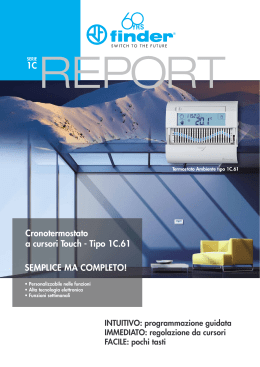
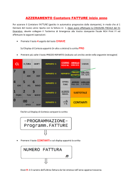
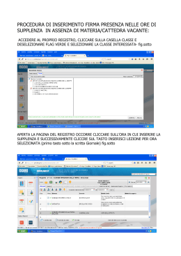
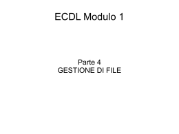
Man. H-520 PLUS
29-03-2007 15:37
Pagina 1
H-520 PLUS
MULTI STANDARD PROGRAMMABLE
27 MHz CB HANDHELD TRANSCEIVER
OWNER'S MANUAL
MANUALE DI ISTRUZIONI
Man. H-520 PLUS
29-03-2007 15:37
Pagina 2
Declaration of Conformity
EC Certificate of Conformity
(to EC Directive 99/5-89/336-93/68-73/23)
DECLARATION OF CONFORMITY
With the present declaration, we certify that the following products :
INTEK H-520 PLUS
comply with all the technical regulations applicable to the above mentioned products
in accordance with the EC Directives 73/23/EEC, 89/336/EEC and 99/5/EC.
Type of product :
CB Transceiver
Details of applied standards :
EN 300 433, EN 300 135-2
EN 301 489-1, EN 301 489-13
EN 60065
Manufacturer :
INTEK S.R.L.
Via G. Marconi, 16
20090 Segrate, Italy
Tel. 39-02-26950451 / Fax. 39-02-26952185
E-mail : [email protected]
Notified Body :
EMCCert Dr. Rasek
Boelwiese 5, 91320 Ebermannstadt
Germany
Identification Number : 0678
Contact Reference :
Armando Zanni
Tel. 39-02-26950451 / Fax. 39-02-26952185
E-mail : [email protected]
Segrate, 12/04/2007
dr. Vittorio Zanetti
(General Manager)
NOTICE !
It is recommended to carefully read this owner’s manual before using the product. This will also help the user to
prevent using the radio in violation of the regulations valid in the country where the product is used, as well as to
avoid any possible interferences with other services.
0678
CH
RoHS
2002/95/EC
Man. H-520 PLUS
29-03-2007 15:37
Pagina 3
Index / Introduction / Content of the package . . . . . . . . . . . . . . . . . . . . . . . . . . . . . . . . . . . . . . . . . . . . 1
Controls, indicators and operation . . . . . . . . . . . . . . . . . . . . . . . . . . . . . . . . . . . . . . . . . . . . . . . . . . 2 - 9
Battery operation . . . . . . . . . . . . . . . . . . . . . . . . . . . . . . . . . . . . . . . . . . . . . . . . . . . . . . . . . . . . . . . . . . 10
Car adaptor operation . . . . . . . . . . . . . . . . . . . . . . . . . . . . . . . . . . . . . . . . . . . . . . . . . . . . . . . . . . . . . . 11
Frequency bands table - User Information . . . . . . . . . . . . . . . . . . . . . . . . . . . . . . . . . . . . . . . . . . . . . 12
Frequency band selection / programming . . . . . . . . . . . . . . . . . . . . . . . . . . . . . . . . . . . . . . . . . . . . . 13
Table of restrictions on the use of CB transceivers . . . . . . . . . . . . . . . . . . . . . . . . . . . . . . . . . . . . . . 13
Specifications . . . . . . . . . . . . . . . . . . . . . . . . . . . . . . . . . . . . . . . . . . . . . . . . . . . . . . . . . . . . . . . . . . . . . 14
Table of restrictions on the use of CB transceivers . . . . . . . . . . . . . . . . . . . . . . . . . . . . . . . . . . . . . . . I
PCB - Main Board . . . . . . . . . . . . . . . . . . . . . . . . . . . . . . . . . . . . . . . . . . . . . . . . . . . . . . . . . . . . . . . II - III
Diagram . . . . . . . . . . . . . . . . . . . . . . . . . . . . . . . . . . . . . . . . . . . . . . . . . . . . . . . . . . . . . . . . . . . . . .IV - VII
Block Diagram . . . . . . . . . . . . . . . . . . . . . . . . . . . . . . . . . . . . . . . . . . . . . . . . . . . . . . . . . . . . . . . . . VIII-IX
NOTICE !
Before using this transceiver, please check that the radio has been programmed on the frequency band,
specifications and operating modes allowed by the regulations valid in the country where the product is used. If
not, please proceed to modify the frequency band programming, as it is described in this owner’s manual. This
transceiver is factory pre-programmed on the CE European frequency band (CEPT 40CH FM 4W).
Congratulations!
Congratulations for selecting and purchasing an INTEK quality product. This transceiver includes a number of advanced
functions and systems, therefore it is definitely necessary to carefully read this owner’s manual before using the radio.
With a correct use of the product in accordance with the operating method described in this manual, the product will offer
a trouble free use for many years. INTEK is constantly engaged to develop and provide quality products meeting the
customers requirements, however any suggestion or comments on this product that might help us to improve quality are
warmly welcome. INTEK H-520 PLUS is a CB transceiver using advanced hardware and software design, it includes
a special multi-standard programmable circuit, which allows to program the specifications of the radio (frequency
bands, operating modes, transmitter power) in compliance with the regulations valid in the various European
countries. Therefore this product can be used in any country of the European Community. The radio is delivered
factory pre-programmed on the CE European frequency band (CEPT 40CH FM 4W).
Using this two-way radio is quite easy and only a few minutes are required to get familiar with it. The operating method
and design are the results of years of experience in the development and production of RF communication equipment,
for personal an professional use. However it is strongly recommended to carefully read this manual in order to get the
maximum performances from your transceiver.
Content of the Package
Please carefully check that all the following items are contained in the packaging :
Transceiver
Rubber antenna
Belt clip with mounting hardware
Carrying strap
User manual
Car adaptor for mobile operation (*)
Travel battery charger 230VAC (*)
(*) These accessories may be included as standard parts only in certain countries.
-1-
English
Index - Introduction - Content of the Package
Man. H-520 PLUS
29-03-2007 15:37
Pagina 4
Controls, Indicators and Operation
English
Front Panel
2
1
3
H-520 PLUS
4
5
21
ESP C E
EMG DW
RX TX SCAN
20
6
LIGHT
ME
AF
LOCK
19
SC
DW
7
MENU
18
17
16
15
8
UP
9
EM
SP
LC
DN
MIC
10
11
14
12
27 MHz AM/FM CB TRANSCEIVER
13
-2-
Man. H-520 PLUS
29-03-2007 15:37
Pagina 5
1.
Antenna Connector
Connect the supplied rubber antenna to this BNC connector, insert and gently turn it clockwise until blocked.
Do not overtighten. If the antenna is not or not correctly connected, damage may be caused to the radio.
2.
SQ/SQL Control
SQL CONTROL (SQUELCH manual adjustment)
The SQL control allows to silent the receiver by cutting the background noise, when no signals are received. Turn the
knob clockwise until the background noise is cut. Turn the knob counter clockwise (SQUELCH opening) in order to listen
to the weakest signals.
SQL CONTROL (SQUELCH fixed setting)
The SQ function allows to automatically silent the receiver, avoding the SQUELCH manual adjustment. A fixed
SQUELCH threshold is factory pre-set. To enable the fixed SQUELCH function, turn the knob fully counter clockwise to
the SQ position, until a click noise is heard.
3.
OFF/VOL (OFF/Volume) Control
This knob switches the radio ON and OFF and it adjusts the volume control. If no signals are being received on the
operating channel, it is suggested to open the SQUELCH and adjust the volume to the desired level while listening to the
background noise.
4.
Handstrap Hole
Hole to insert and attach the supplied carrying handstrap.
5.
LCD Display
Large size (1.8”) LCD display with green color backlight function for best readability in darkness. The large
5-line LCD indicates simultaneously all the programmed settings and all the enabled functions, such as
the operating channel number and the full frequency readout in KHz (5 digits), the programmed frequency
band ID code, the AM or FM operating mode, the transmitter RF output power, the used memory channel
if any as well as every other set function. Digital 10-bar S/RF/MOD Meter and 4-bar battery level indicator.
LCD Display
A
B
C
S
D
E
R
F
Q
ESP C E
G
EMG DW
H
RX TX SCAN
P
O
N
M
-3-
L
I
English
Controls, Indicators and Operation
Man. H-520 PLUS
29-03-2007 15:37
Pagina 6
Controls, Indicators and Operation
English
A. Channel Number
Channel number indication (from 01 to 80, according to the selected frequency band).
B. Alpha-numeric Indication
Not available and not used indication on the radios for the European market.
C. Frequencu Readout
Full 5-digit frequency readout in KHz.
D. Transmitter RF Output Power
It indicates the selected transmitter RF output power (0.1W, 1.0W or 4.0W). The 4.0W RF output power level is available
only on the frequency bands where this power level is allowed.
E.
Memory Channel Number (M1-M8)
It indicates the selected memory channel number, total 8 memory channels are available (M1-M8), if any.
F.
EMG Icon
The EMG icon is lighted when one of the pre-programmed Emergency Channels has been selected.
G. DW Icon
The DW icon is lighted when the DW (DUAL WATCH) function has been enabled, in order to automatically monitor two
different channels.
H. SCAN Icon
The SCAN icon is lighted when the SCAN function has been enabled, in order to automatically search busy channels or
busy memory channels.
I.
TX Icon
The TX icon is ligthed when radio is in the transmit mode.
L.
RX Icon
The RX icon is ligthed when radio is in the receive mode.
M. ESP C E Icon
The ESP C E icon is lighted when the ESP (Electronic SPEECH PROCESSOR) function has been enabled.
N. Battery Level Indicator
It shows the current battery level condition.
O. FM Icon
The FM icon is lighted when radio has been set to the FM (Frequency Modulation) operating mode.
P.
AM Icon
The AM icon is lighted when radio has been set to the AM (Amplitude Modulation) operating mode.
Q. LOCK Icon
The LOCK icon is lighted when the keypad lock function has been enabled.
R. S/RF/MOD Digital Bar Meter
The 10-bar digital meter indicates the received signal strength (S0 to S9+30) in the receive mode.
It indicates the transmitter RF output power (0 to 4W) or the modulation level in the transit mode.
-4-
Man. H-520 PLUS
29-03-2007 15:37
Pagina 7
S.
Frequency Band ID Code
It indicates the programmed frequency band ID code (i.e. DE, UK, CE, etc.).
6.
AF (AM/FM) Key
Use the AF key to select the AM or FM operating mode in both RX and TX. The AM/FM operating mode selection is
possible only if it is allowed by the programmed frequency band, otherwise the AM/FM selection is not possible. If the
UK (United Kingdom) frequency band has been programmed, press and hold this key for about 2 seconds to select the
UK channels (UK frequencies) or the CE channels (CE frequencies).
7.
MENU Key
Use the MENU (7) key to enable and program the various functions of the radio. Pressing the MENU (7) key will scroll
the various functions. The sequence of the various functions might change depending on the currently enabled function.
RF/MOD DIGITAL METER MODE SELECTION
The 10-bar digital Meter indicates the transmitter RF output power (0 to 4W) or the modulation level. Select the digital
Meter reading mode by pressing the MENU (7) key several times, until the indication Pwr (transmitter RF power) or Mod
(modulation level) appears on the LCD. Use the UP (9) or DN (10) keys to select the desired reading mode and shortly
press the PTT key (21) to confirm and store your selection.
KEYPAD PROGRAM TONE
When a key is pressed, a beep tone is heard to confirm your command. You may enable or disable this keypad program
tone, by pressing the MENU (7) key several times, until the indication be EPOFF (program tone OFF) or be EP On
(program tone ON) appears on the LCD. Use the UP (9) or DN (10) keys to set the desired selection and shortly press
the PTT key (21) to confirm and store your selection.
TRANSMITTER RF POWER SETTING
The transmitter RF output power is selectable in 3 levels (0.1W, 1.0W or 4.0W) in both AM and FM modes. This function
is very convenient to reduce the current drain and extend battery life when communicating within short distance. Press
the MENU (7) key several times, until the LCD will show the current power level Pw Er AM 4.0W (Pw Er FM 4.0W),
Pw Er AM 1.0W (PwEr FM1.0W) or Pw Er AM 0.1W (Pw Er FM 4.0W). Use the UP (9) or DN (10) keys to set the
desired RF power level and shortly press the PTT key (21) to confirm and store your selection.
LCD DISPLAY BACKLIGHT SETTING
Press the MENU (7) key several times, until the LCD will show the current backlight setting bl OFF (backlight disabled),
bl ON (backlight enabled manual) o bl Auto (backlight enabled automatic). Use the UP (9) or DN (10) keys to set the
desired selection and shortly press the PTT key (21) to confirm and store your selection.
-5-
English
Controls, Indicators and Operation
Man. H-520 PLUS
29-03-2007 15:37
Pagina 8
Controls, Indicators and Operation
English
8.
DW Key
The DW (Dual Watch) function allows automatic alternate monitoring of two programmable channels. Select the first
channel to be monitored using the UP (9) or DN (10) keys. To enable the DW function, close the Squelch by turning the
SQ/SQL knob, then press the DW (8) key for about 2 seconds, until the DW icon (G) appears on the LCD display. Now
select the second channel to be monitored using the UP (9) or DN (10) keys and press again the DW (8) key for about 2
seconds. The DW function is now enabled and the LCD display will alternately show the channel number of the two
programmed channels. The DW icon (G) will be lighted on the LCD display. Monitoring stops if a signal is detected on
one of the two channels, in order to let the user listen to the incoming signal and will start again when no signal is
detected on that channel. It is possible to transmit on that channel, by simply pressing the PTT key (21). If there is no
transmission within 5 seconds, monitoring will re-start. To exit the DW mode, shortly press the PTT button (21).
9.
UP (QUICK UP) Key
Shortly press the UP (9) key to increase the channel number by one channel up at every key press. Press and hold the
UP (9) key to increase channels by 10 channels up at each time (quick up channel slection).
10. DN (QUICK DN) Key
Shortly press the DN (10) key to decrease the channel number by one channel down at every key press. Press and hold
the DN (10) key to decrease channels by 10 channels down at each time (quick down channel slection).
11. LC Key
Shortly press the LC (Last Channel Recall) key (11) to automatically re-set radio on the last used channel.
12. Built-in Speaker
Built-in front speaker.
13. Car Adaptor Contacts
Car adaptor contacs and fixing screw.
14. Built-in Microphone
Built-in microphone.
15. EM Key
Press the EM key (15) to fast access the pre-programmed emergency channels (CH9 or CH19). Each time the EM key
(15) is pressed, radio will move to CH9, then to CH19, then back to the current operating channel. Please refer to the
below table for the factory pre-programmed emergency channels.
FREQUENCY BAND
ID CODE
E1
I2
DE
D2
EU
CE
UK
PL
CH-9
AM
AM
AM
AM
AM
FM
FM
AM
CH-19
AM
AM
AM
AM
AM
FM
FM
AM
-6-
Man. H-520 PLUS
29-03-2007 15:37
Pagina 9
16. SP (Speech Processor) Key
The ESP (Electronic Speech Processor) is a unique feature available in some INTEK two-way CB radios. ESP means
Electronic Speech Processor, in other words electronic modulation processor. This audio processor is microprocessor
controlled and it is also called COMPANDER (Compressor-Expander). It works as a modulation compressor in transmit
mode and as a modulation expander in receive m ode. The ESP allows to obtain a stronger, clear and clean audio signal
and it is a great help in noisy areas and in case of weak signals or in long distance communication. The efficiency of
ESP is even greater when both stations use this device. The 2nd generation ESP allows to enable only the TX
compressor, only the RX expander or both systems.
To enable or disable the ESP functions, press the SP key (16), as follows :
1)
Press the key once to enable the TX modulation compressor. The ESP C (M) icon will appear on the LCD.
2)
Press the key again to enable the RX modulation expander. The ESP E (M) icon will appear on the LCD.
3)
Press the key again to enable both the TX modulation compressor and the RX modulation expander.
The ESP C E (M) icon will appear on the LCD.
4)
Press the key once again to disable all systems.
100%
ESP performance
of the modulation
in RX and TX modes
0%
100%
Modulation without ESP
Modulation with ESP
17. LOCK Key
Press the LOCK (17) key for a few seconds to enable the keypad LOCK function. Press the key again to disable.
18. SCAN Key
Turn the SQL (2) control clockwise until the background noise is cut, otherwise the automatic SCAN function cannot
start. Press the SCAN (18) key to start the automatic channels scanning. The SCAN (H) icon will appear on the LCD.
SCAN will automatically stop when a signal is detected on one channel, in order to listen to the communication and
SCAN will re-start when no more signal is detected on that channel. Shortly press the PTT (21) key within 5 seconds if
you want to stay on that channel, otherwise SCAN will re-start. If you have no interest on the communication on that
channel, just press the UP (9) or DN (10) keys and SCAN will immediately re-start upward or downward. To exit the
SCAN mode, shortly press the PTT (21) key. You may also SCAN the memory channels only, just recall one of the
stored memory channels (refer to ME Key), then enable and start the SCAN function.
19. LIGHT Key
Press the LIGHT (19) key to backlight the LCD display, press the key again to switch OFF backlight. Select the desired
LCD display backlight mode as indicated at item 7. LCD Display Backlight Setting.
-7-
English
Controls, Indicators and Operation
Man. H-520 PLUS
29-03-2007 15:37
Pagina 10
Controls, Indicators and Operation
English
20.
ME Key
PROGRAMMING MEMORY CHANNELS (M1-M8)
Use the UP (9) or DN (10) keys to select the channel to be stored as a memory channel. Press the ME (20) key for
about three seconds until the M1 (E) icon appears on the LCD. Now use the UP (9) or DN (10) keys to select the
memory channel number where the previously selected channel must be stored. To store, press and hold the MENU (7)
key for about two seconds, until the previously selected channel number will appear on the LCD. All the datas of that
channel will be stored (channel number, frequency readout, AM/FM mode, transmitter power, etc.).
MEMORY CHANNELS RECALL
Shortly press the ME (20) key to access the stored memory channels. The memory channel number (M1- M8) will
appear on the LCD (i.e. M1). Use the UP (9) or DN (10) keys to select the desired memory channel.
Press again the ME (20) key to exit the memory channels recall mode.
21. PTT (Push-To-Talk) Key
Press the PTT (21) key to transmit and hold it during transmission. The TX (I) icon will be lighted during transmission.
Release the key at the end of your transmission to return to the receive mode.
WARNING ! Do not touch the antenna during transmission.
Rear Panel
22
23
24
-8-
Man. H-520 PLUS
29-03-2007 15:38
Pagina 11
22. Earset-Microphone-Charge Jack
Connect an external earset-microphone to this jack. Connect the 230VAC battery travel charger (AC-520) to this jack.
WARNING !
Use only original accessories. Connecting and using accessories other than the original ones, may cause
serious damage to the radio and will void the warranty.
Always set the volume to minimum before connecting an external earset, in order to avoid damaging the earset
or the user’s ear.
23.
Belt Clip
24. Battery Door
Open this cover (24) to install or remove batteries.
25. Battery Type Selector
The battery type selector (25) is located inside the battery room. Set the switch (25) to Ni if rechargeable batteries are
used. Set the switch (25) to AL if alkaline batteries are used.
+
-
-
+
-
+
-
+
-
+
-
+
25
NI
AL
WARNING !
Do never try to open the cabinet of the radio. No user serviceable parts are inside the cabinet. Tampering or
modifying the circuit of the radio or its original factory adjustment may cause damage to the product, may change
the electrical specifications and will void the warranty. If service is required, please refer only to a qualified and
authorized service center.
-9-
English
Controls, Indicators and Operation
Man. H-520 PLUS
29-03-2007 15:38
Pagina 12
Battery Operation
English
Installing and Checking Batteries
Slide down and remove the battery door (24) and to access the battery room. Set the battery type switch (25)
according to the type of used batteries (Ni for rechargeable batteries and AL for alkaline batteries). Install 6 x AA size
alkaline batteries or rechargeable batteries and pay attention to install it with the correct polarity as indicated in the
battery room. Switch ON radio by turning the OFF/VOL (3) control and check the battery level on the battery level
indicator (N), 4 bars mean full charge, 3 bars mean normal charge, 2 bars mean half charge and 1 bar means low
battery condition. If no bars appear, batteries must be immediately replaced or recharged. Please refer to the
following item BATTERY CHARGING.
Battery Charging
If the battery level indicator (N) shows a low battery condition, switch OFF the radio and connect the battery travel
charger mod. AC-520 to the CHARGE jack (22), then plug it into the 230VAC outlet. To obtain the maximum
performance from the batteries, recharge them only when they are fully discharged. The charging time depends on the
capacity of the used batteries, it is approximately 12 hours for one set of Ni-MH batteries (1200-1500mAh). When the
charging time has expired, unplug the charger from the AC outlet and then disconnect it from the radio.
WARNING !
1.
Only the Ni-MH (or Ni-CD) batteries may be recharged.
2.
Do never try to recharge alkaline batteries, as this might cause damage to the radio or explosion of the
batteries.
3.
Set the battery type selector (25) to Ni.
4.
Always switch OFF radio before starting the battery charging process.
5.
Do not recharge batteries for more than 13-14 hours, in order to avoid overcharge or overheating, which could
cause damage to the radio.
6.
Use only the enclosed battery charger or original INTEK battery chargers.
- 10 -
Man. H-520 PLUS
29-03-2007 15:38
Pagina 13
Operation of the Car Adaptor (CAR-520)
This handheld radio can be turned into a mobile transceiver by connecting the Car Adaptor CAR-520. The Car Adaptor
will supply a regulated DC power to the radio, directly from the car cigarette lighter plug as well as the connection for an
external antenna. Install the Car Adaptor as follows :
1.
Remove the rubber antenna from the radio.
2.
Open the battery door (24) and remove batteries (at least one cell). The DC power to the radio will be supplied by
the car electric circuit via the Car Adaptor.
3.
Connect the Car Adaptor to the radio, as showed in the below picture.
4.
Lock the Car Adaptor to the radio by turning the knob (26) in the LOCK direction as indicated by the arrow. Do not
overtighten this screw.
5.
Connect the cigarette lighter adaptor into the cigarette lighter plug in the vehicle (12VDC).
6.
Connect an external antenna to the SO-239 antenna connector of the Car Adaptor.
WARNING ! Batteries (at least one cell) must be removed while using the Car Adaptor, if this is connected to the
car electric system. Non observance of this precaution may cause damage to the radio and explosion of the
batteries and will void warranty.
24
CK
LO
- 11 -
26
English
Car Adaptor Operation
Man. H-520 PLUS
29-03-2007 15:38
Pagina 14
Frequency Bands Table - User Information
English
Frequency Bands Table
The INTEK H-520 PLUS transceiver includes an advanced multi-standard programmable circuit design, which allows to
program the radio in accordance with the frequency band, operating modes, transmitter RF output power in full
compliance with the local regulations of the country where the radio will be used. A total of 8 programmable frequency
bands are available, as per the following table :
FREQUENCY BAND
ID CODE
E1
I2
DE
D2
EU
CE
ITALY/SPAIN
ITALY
GERMANY
GERMANY
EUROPE/FRANCE
CEPT
UK
UK
PL
POLAND
SPECIFICATIONS
(Channels, Operating Modes, TX Power)
COUNTRY
40CH AM / FM 4W
36CH AM / FM 4W
80CH FM 4W - 12CH AM 1W
40CH FM 4W - 12CH AM 1W
40CH FM 4W - 40CH AM 1W
40CH FM 4W
40CH FM 4W UK FREQUENCIES
40CH FM 4W CEPT FREQUENCIES
40CH AM / FM 4W POLISH FREQUENCIES
WARNING ! The radio has been factory pre-programmed on the CE (CEPT 40CH FM 4W) frequency band, as this
standard is currently accepted by all the European countries. Please refer to the information table at page I
(Restrictions on the use of CB transceivers).
User Information
in accordance with art. 13 of the Legislative Decree of 25th July 2005, no. 15 ”Implementation of Directives 2002/95/EC,
2002/96/EC and 2003/108/EC, relative to reduction of the use of hazardous substances in electrical and electronic
equipment, in addition to waste disposal”.
The crossed bin symbol shown on the equipment indicates that at the end of its working life the product must
be collected separately from other waste.
The user must therefore take the above equipment to the appropriate differentiated collection centres for
electronic and electro technical waste, or return it to the dealer when purchasing a new appliance of
equivalent type, in a ratio of one to one.
Appropriate differentiated waste collection for subsequent recycling, treatment and environment-friendly disposal of the
discarded equipment helps to prevent possible negative environmental and health effects and encourages recycling of
the component materials of the equipment.
Illegal disposal of the product by the user will be punished by application of the administrative fines provided for by the
legislative decree no. 22/1997 (article 50 and following of the legislative decree no. 22/1997).
- 12 -
Man. H-520 PLUS
29-03-2007 15:38
Pagina 15
Frequency Band Selection / Programming
The radio must be programmed and used exclusively on the frequency band allowed by the regulations of the country
where the radio will be used. In order to program the frequency band, please refer to the following instructions :
1.
Turn OFF radio.
2.
Press and keep pressed the MENU (7) key while switching ON radio, by turning the OFF/VOL (3) control
clockwise.
3.
The current programmed frequency band ID code (S) appears on the LCD.
4.
Using the UP (9) or DN (10) keys, select a new frequency band ID code.
5.
Shortly press the MENU (7) key to confirm and store.
Table of Restrictions on the Use of CB Transceivers (page I)
The following information are to be considered only just as an indication. They are believed to be correct at the time of
printing this operating manual. It is however the user’s responsibility to check that, in the country where radio is used, the
regulations for the use of CB transceivers have not been modified. User is therefore suggested to contact the local
dealer or local authority, in order to check the current regulations for the use of CB transceivers, before operating this
product. The manufacturer does not take any responsibility if the product is used in violation of the regulations of the
country where the product is used.
Addendum (Updated information on national restrictions)
BELGIUM, UK, SPAIN, SWITZERLAND
In order to use this transceiver in Belgium, UK, Spain and Switzerland, residence must have an individual licence. Users
coming from abroad may freely use the radio in FM mode, while in order to use it in AM mode they must hold a licence
released in their own country.
ITALY
Foreigners arriving in Italy must get an Italian authorization.
AUSTRIA
Austria does not allow using multi standard programmable CB radios. It is recommended to carefully follow this
directives and not to use the product in the Austrian territory.
GERMANY
Along some border areas in Germany, the radio can not be used as a base station from channel 41 to channel 80. Refer
to local authority (notification office) for details.
- 13 -
English
Frequency Bands Selection / Programming
Man. H-520 PLUS
29-03-2007 15:38
Pagina 16
Specifications
English
Specifications
General
Channels
Frequency range
Frequency control
Operatine temperature
DC input voltage
Size
Weight
40 FM (refer to the frequency bands table at page 12)
25.610 - 30.105 MHz
P.L.L.
-10°/+55°C
9.0V (6 x AAA 1.5V alkaline battery)
7.2V (6 x AAA 1.2V Ni-MH battery)
68 (L) x 146 (H) x 38 (D) mm
218 gr. (without batteries and antenna)
Receiver
System
IF
Sensitivity
Audio output
Audio distorsion
Image rejection
Adjacent channel
Signal/noise ratio
Current drain
Double conversion, CPU controlled super-eterodine
1° 10.695 MHz / 2° 455 KHz
0.5uV for 20dB SINAD (FM)
0.7uV for 20dB SINAD (AM)
0.3W at 8 ohm
<8% at 1 KHz
61dB
61dB
45dB
70mA (stand-by)
Transmitter
System
Maximum RF power
Modulation
Impedance
Current drain
CPU controlled P.L.L. systhesizer
4W at 9.0Vdc
AM/FM
50 ohm unbalanced
1500mA (at no modulation)
- 14 -
Man. H-520 PLUS
29-03-2007 15:38
Pagina 17
Indice / Introduzione / Contenuto della confezione . . . . . . . . . . . . . . . . . . . . . . . . . . . . . . . . . . . . . . 15
Descrizione dei comandi, indicatori e funzionamento . . . . . . . . . . . . . . . . . . . . . . . . . . . . . . . . . 16-23
Utilizzo delle batterie . . . . . . . . . . . . . . . . . . . . . . . . . . . . . . . . . . . . . . . . . . . . . . . . . . . . . . . . . . . . . . . 24
Utilizzo dell' adattatore veicolare . . . . . . . . . . . . . . . . . . . . . . . . . . . . . . . . . . . . . . . . . . . . . . . . . . . . . 25
Tabella bande di frequenza - Avviso agli utenti . . . . . . . . . . . . . . . . . . . . . . . . . . . . . . . . . . . . . . . . . 26
Selezione / programmazione della banda di frequenza . . . . . . . . . . . . . . . . . . . . . . . . . . . . . . . . . . . 27
Tabella delle restrizioni all' uso dei ricetrasmettitori CB . . . . . . . . . . . . . . . . . . . . . . . . . . . . . . . . . . 27
Caratteristiche tecniche . . . . . . . . . . . . . . . . . . . . . . . . . . . . . . . . . . . . . . . . . . . . . . . . . . . . . . . . . . . . 28
Tabella delle restrizioni all' uso dei ricetrasmettitori CB . . . . . . . . . . . . . . . . . . . . . . . . . . . . . . . . . . . I
Circuito stampato Main Board . . . . . . . . . . . . . . . . . . . . . . . . . . . . . . . . . . . . . . . . . . . . . . . . . . . . . .II-III
Schema elettrico . . . . . . . . . . . . . . . . . . . . . . . . . . . . . . . . . . . . . . . . . . . . . . . . . . . . . . . . . . . . . . . IV-VII
Schema a blocchi . . . . . . . . . . . . . . . . . . . . . . . . . . . . . . . . . . . . . . . . . . . . . . . . . . . . . . . . . . . . . . VIII-IX
IMPORTANTE !
Prima di utilizzare la ricetrasmittente, verificare che la stessa sia programmata per operare sulla banda di
frequenza e nei modi previsti dalle norme di legge in vigore nel paese in cui la radio viene utilizzata. Diversamente
procedere alla modifica della programmazione, come indicato in questo manuale di istruzioni. La radio è preprogrammata all' origine sulla banda di frequenza europea CE (CEPT 40CH FM 4W).
Congratulazioni !
Congratulazioni per aver scelto ed acquistato un prodotto di qualità INTEK. Questo ricetrasmettitore dispone di numerose
funzioni avanzate e alcuni dispositivi esclusivi. Con un uso corretto secondo quanto è indicato nel manuale di istruzioni, l'
apparecchio garantirà un servizio senza problemi per molti anni. Ci impegniamo costantemente a fornire prodotti di
qualità che rispondano alle vostre esigenze, ma siamo comunque sempre molto interessati a ricevere eventuali vostri
commenti o suggerimenti su questo prodotto. INTEK H-520 PLUS è un ricetrasmettitore con caratteristiche tecniche di
hardware e software molto avanzate e dispone di un circuito di tipo Multi Standard programmabile che consente di
configurare i vari parametri dell' apparecchio (bande di frequenza, modi operativi, potenza del trasmettitore) in modo
conforme alle norme di legge in vigore nei vari paesi della Comunità Europea. Questa radio è quindi utilizzabile in un
qualsiasi paese della Comunità Europea. L' apparecchio è pre-programmato sulla banda CE (CEPT 40CH FM 4W).
L' utilizzo di questo apparato é estremamente semplice; solo pochi minuti sono necessari per prenderne familiarità. Le
modalità operative dei comandi e delle funzioni, sono il risultato di anni di esperienza nel campo dei ricetrasmettitori, per
uso personale e professionale. Per ottenere le massime prestazioni dal ricetrasmettitore, consigliamo di prendere
attentamente visione del manuale prima di iniziarne l' uso.
Contenuto della confezione
Controllare attentamente che la confezione contenga i seguenti componenti :
Manuale di istruzioni
Adattatore per uso veicolare (*)
Carica batterie da viaggio 230VAC (*)
Ricetrasmettitore
Antenna in gomma
Clip da cintura con viti di fissaggio
Cinghietta di trasporto
(*) Questi accessori possono essere inclusi in dotazione solo in alcuni paesi.
- 15 -
Italiano
Indice - Introduzione - Contenuto della confezione
Man. H-520 PLUS
29-03-2007 15:38
Pagina 18
Descrizione dei comandi, indicatori e funzionamento
Pannello frontale
2
Italiano
1
3
H-520 PLUS
4
5
21
ESP C E
EMG DW
RX TX SCAN
20
6
LIGHT
ME
AF
LOCK
19
SC
DW
7
MENU
18
17
16
15
8
UP
9
EM
SP
LC
DN
MIC
10
11
14
12
27 MHz AM/FM CB TRANSCEIVER
13
- 16 -
Man. H-520 PLUS
29-03-2007 15:38
Pagina 19
Descrizione dei comandi, indicatori e funzionamento
2.
Manopola SQ/SQL
COMANDO SQL (regolazione manuale SQUELCH)
Il comando SQL permette di silenziare il ricevitore, eliminando il rumore (fruscio) di fondo in assenza di segnali. Ruotare
la manopola in senso orario sino a quando scompare il rumore di fondo. Ruotare la manopola in senso antiorario
(apertura dello SQUELCH) per ascoltare i segnali più deboli.
COMANDO SQ (regolazione fissa SQUELCH)
E' disponibile la funzione SQ per silenziare il ricevitore in modo automatico, senza eseguire la regolazione manuale dello
SQUELCH. Una regolazione fissa dello SQUELCH è pre-impostata in origine. Per impostare la funzione SQ, ruotare la
manopola completamente in senso antiorario fino a farla scattare in posizione SQ.
3.
Manopola OFF/VOL
Manopola di accensione e spegnimento della radio. Permette la regolazione del volume di ascolto. In assenza di segnali
sul canale in uso, si consiglia di aprire lo SQUELCH e quindi di regolare il volume al livello desiderato utilizzando come
riferimento il rumore (fruscio) di fondo.
4.
Foro per laccetto
Foro per l’ inserimento della cinghietta di trasporto.
5.
Display LCD
Display LCD di grande dimensione (1.8”) e di tipo retro-illuminato in colore verde, per la massima
leggibilità anche nell’oscurità. Il grande display a 5 linee indica simultaneamente tutti i parametri in uso e
tutte funzioni e i dispositivi attivati, tra cui la lettura del numero del canale e della frequenza completa in
KHz a 5 cifre, il codice della banda di frequenza programmata, il modo operativo AM o FM, la potenza RF
del trasmettitore, il numero della eventuale memoria in uso e le varie altre funzioni impostate. Strumento
indicatore tipo S/RF/MOD Meter digitale a 10 barre e indicatore livello batteria a 4 segmenti.
Display LCD
A
B
C
S
D
E
R
F
Q
ESP C E
G
EMG DW
H
RX TX SCAN
P
O
N
M
- 17 -
L
I
Italiano
1.
Presa per antenna
Connettore BNC per il collegamento dell’ antenna in gomma in dotazione. Inserire e ruotare gentilmente in senso orario
per bloccare, non forzare. Il mancato inserimento può causare danni al ricetrasmettitore.
Man. H-520 PLUS
29-03-2007 15:38
Pagina 20
Descrizione dei comandi, indicatori e funzionamento
A. Indicazione del canale
L' indicazione consente la lettura del numero del canale in uso (da 01 a 80, secondo la banda programmata).
B. Indicazione alfanumerica
Indicazione non disponibile e non utilizzata negli apparecchi destinati al mercato Europeo.
Italiano
C. Indicazione della frequenza
L' indicazione permette la lettura completa della frequenza in uso a 5 cifre (in KHz).
D. Indicazione della potenza di trasmissione
L' indicazione visualizza la potenza RF selezionata del trasmettitore (0.1W, 1.0W or 4.0W). La potenza di 4.0W è
disponibile solo nelle bande di frequenza ove questo livello di potenza è ammesso.
E.
Indicazione della memoria (M1-M8)
L' indicazione delle memorie (M1-M8) è accesa quando è stato selezionato 1 degli 8 canali programmabili di memoria.
F.
Indicazione EMG
L' indicazione EMG è accesa quando è stato selezionato uno dei canali speciali di emergenza pre-programmati secondo
la banda selezionata.
G. Indicazione DW
L' indicazione DW è accesa quando è attiva la funzione DUAL WATCH, ovvero il monitoraggio automatico di 2 canali.
H. Indicazione SCAN
L' indicazione SCAN è accesa quando è attiva la funzione di scansione SCAN, ovvero la ricerca automatica delle
memorie o dei canali occupati.
I.
Indicazione TX
L' indicazione TX è accesa quando il ricetrasmettitore è in modalità trasmissione.
L.
Indicazione RX
L' indicazione RX è accesa quando il ricetrasmettitore è in modalità ricezione.
M. Indicazioni ESP C E
L' indicazione ESP C E è accesa quando è attivata la funzione Electronic Speech Processor, ovvero il processore
elettronico di modulazione RX e TX.
N. Indicazione livello batteria
Visualizza lo stato di carica delle batterie a 4 livelli.
O. Indicazione FM
L' indicazione FM è accesa quando il ricetrasmettitore riceve e trasmette in modo FM (modulazione di frequenza).
P.
Indicazione AM
L' indicazione AM è accesa quando il ricetrasmettitore riceve e trasmette in modo AM (modulazione di ampiezza).
Q. Indicazione LOCK
L' indicazione LOCK è accesa quando la funzione di blocco tastiera è attiva.
R. Strumento digitale a barre S/RF/MOD Meter
Lo strumento a 10 barre S/RF/MOD Meter indica l' intensità del segnale ricevuto da S0 a S9+30 in ricezione, la potenza
RF di uscita da 0 a 4W in trasmissione oppure il livello di modulazione in trasmissione.
- 18 -
Man. H-520 PLUS
29-03-2007 15:38
Pagina 21
Descrizione dei comandi, indicatori e funzionamento
6.
Tasto AF (AM/FM)
Questo tasto permette di selezionare il modo operativo AM o FM in ricezione e trasmissione. La selezione del modo
AM/FM è abilitata solamente se ammessa dalla banda di frequenza/modo programmata, diversamente la selezione non
è possibile. Se è stata programmata la banda di frequenza UK (Gran Bretagna), premendo per circa 2 secondi questo
tasto è possibile la selezione tra i canali (frequenze) UK e i canali (frequenze) CE.
7.
Tasto MENU
Il tasto MENU (7) permette di abilitare e programmare le diverse funzioni della radio. Ad ogni pressione del tasto MENU
(7), è possibile selezionare in sequenza una delle varie funzioni. L’ ordine delle funzioni può cambiare di volta in volta, a
seconda delle impostazioni attive in quel momento.
SELEZIONE DELLA LETTURA RF/MOD Meter
Lo strumento digitale a 10 barre RF/MOD Meter (R) indica a scelta la potenza RF di uscita da 0 a 4W in trasmissione o il
livello della modulazione. Per selezionare l’ indicazione voluta premere il tasto MENU (7) finchè viene visualizzata sul
display LCD la scritta Pwr (lettura potenza RF di uscita) o Mod (livello di modulazione). Agendo su i tasti UP (9) o DN
(10) selezionare l’ indicazione voluta e premere il tasto PTT (21) per confermare.
IMPOSTAZIONE DEL TONO DI PROGRAMMAZIONE
Ogni qualvolta viene premuto un tasto della radio, un tono beep viene emesso a conferma del comando inserito. Questa
funzione può essere attivata o disattivata dall’ utente. Per attivare o disattivare questa funzione premere il tasto MENU
(7) finchè viene visualizzata sul display LCD la scritta be EPOFF (tono Beep disabilitato) o be EP On (tono abilitato).
Agendo su i tasti UP (9) e DN (10) selezionare l’ impostazione desiderata e confermare premendo il tasto PTT (21).
REGOLAZIONE DELLA POTENZA DI TRASMISSIONE
La potenza di uscita del trasmettitore può essere selezionata in 3 livelli (0.1W, 1.0W, 4.0W), sia nel modo AM che FM,
funzione molto utile per ridurre il consumo delle batterie durante le comunicazioni a breve distanza. Il livello di potenza
4W è attivo solo nelle bande di frequenza ove questo livello di potenza è ammesso. Per selezionare il livello di potenza
desiderato premere il tasto MENU (7), finchè viene visualizzata sul display LCD la scritta Pw Er AM 4.0W (Pw Er FM
4.0W), Pw Er AM 1.0W (Pw Er FM1.0W) o Pw Er AM 0.1W (Pw Er FM 4.0W). Agire sui tasti UP (9) e DN (10) per
selezionare uno dei 3 livelli e premere il tasto PTT (21) per confermare.
IMPOSTAZIONE DELLA RETROILLUMINAZIONE DEL DISPLAY LCD
Per selezionare questa funzione premere il tasto MENU (7) finchè viene visualizzata sul display LCD la scritta bl OFF
(illuminazione disabilitata), bl ON (illuminazione abilitata manuale ) o bl Auto (illuminazione abilitata automatica) e agire
su i tasti UP (9) e DN (10) per selezionare l’ impostazione desiderata. Impostando bl ON è possibile, ad ogni pressione
del tasto LIGHT (19), accendere o spegnere a piacimento la retroilluminazione del display. Impostando invece bl Auto,
ad ogni pressione del tasto LIGHT (19), la retroilluminazione avrà una durata di 5 secondi, dopodiché si spegnerà
automaticamente. Per confermare la selezione desiderata, premere il tasto PTT (21).
- 19 -
Italiano
S.
Indicazione banda di frequenza
Questa indicazione permette la lettura del codice di identificazione della banda di frequenza programmata (es. DE, UK,
CE, ecc.).
Man. H-520 PLUS
29-03-2007 15:38
Pagina 22
Descrizione dei comandi, indicatori e funzionamento
Italiano
8.
Tasto DW
La funzione DW (Dual Watch) permette il monitoraggio automatico alternato di 2 canali programmabili. Selezionare il
primo canale da monitorare tramite i tasti UP (9) e DN (10). Per attivare la funzione DW, chiudere lo Squelch agendo sul
comando SQ/SQL (2) e premere il tasto DW (8) per circa 2 secondi fino a che l' indicatore DW (G) appare sul display.
Selezionare ora il secondo canale da monitorare tramite i tasti UP (9) e DN (10) e premere di nuovo il tasto DW (8) per
circa 2 secondi. La funzione DW è ora attiva e sul display verranno indicati alternativamente i numeri dei 2 canali. L'
icona DW (G) sarà accesa. Quando viene rilevato un segnale su uno dei 2 canali, il monitoraggio si arresta per
permettere l' ascolto della comunicazione e riprenderà quando non verrà rilevato alcun segnale su quel canale. Se per 5
secondi non si trasmette, il monitoraggio alternato dei 2 canali viene ripreso. In caso contrario è possibile effettuare una
comunicazione su quel canale. Per uscire dalla funzione DW, premere rapidamente il tasto PTT (21) o il tasto DW (8).
9.
Manopola UP (Quick UP)
Questo tasto permette la selezione dei canali in ordine crescente. Mantenendo premuto questo tasto il numero del
canale viene aumentato di 10 canali per volta.
10. Tasto DN (Quick DN)
Questo tasto permette la selezione dei canali in ordine decrescente. Mantenendo premuto questo tasto il numero del
canale viene aumentato di 10 canali per volta.
11. Tasto LC
Premendo il tasto LC (Last Channel Recall) (11), il ricetrasmettitore viene automaticamente riportato sull' ultimo canale
precedentemente utilizzato.
12. Altoparlante incorporato
Altoparlante entro contenuto.
13. Attacco per adattatore veicolare
Attacco per il fissaggio dell’ adattatore per uso veicolare (Car Adaptor).
14. Microfono
Microfono di tipo Electret, entro contenuto.
15. Tasto EM (Emergency Channels)
Questo tasto permette la selezione rapida di uno dei 2 canali di emergenza pre-programmati (CH9 o CH19). Ad ogni
pressione del tasto, viene impostato il canale CH9, quindi il canale CH19, quindi nuovamente il normale canale in uso.
Vedere la tabella seguente per canali di emergenza pre-programmati all' origine.
CODICE BANDA
DI FREQUENZA
E1
I2
DE
D2
EU
CE
UK
PL
CH-9
AM
AM
AM
AM
AM
FM
FM
AM
CH-19
AM
AM
AM
AM
AM
FM
FM
AM
- 20 -
Man. H-520 PLUS
29-03-2007 15:38
Pagina 23
16. Tasto SP (Electronic Speech Processor)
L' ESP (Electronic Speech Processor) di 2° generazione è un dispositivo esclusivo di alcuni ricetrasmettitori CB mobili
INTEK. ESP significa Electronic Speech Processor, cioè processore elettronico di modulazione.
Questo processore audio, controllato da microprocessore e denominato anche COMPANDER (Compressor- Expander),
lavora come compressore di modulazione in trasmissione e come espansore di modulazione in ricezione. L' ESP
consente di ottenere un segnale audio più forte, chiaro e pulito ed è un notevole aiuto in zone rumorose, in caso di
comunicazioni a lungo raggio e con segnali deboli. L' efficenza dell' ESP è maggiore se si comunica con altre radio
dotate dello stesso sistema. Questo dispositivo di seconda generazione consente di attivare o disattivare separatamente
solo il compressore, solo l’ espansore o entrambi i modi compressore-espansore.
Per attivare o disattivare le funzioni ESP, premere il tasto SP (16) in sequenza :
1)
Premendo una volta il tasto, l' indicazione ESP C (M) appare sul display per indicare che è inserito solo il circuito
compressione della modulazione.
2)
Premendo due volte il tasto, l' indicazione ESP E (M) appare sul display per indicare che è inserito solo il
circuitoespansore della modulazione.
3)
Premendo tre volte il tasto, l' indicazione ESP C E (M) appare sul display per indicare che è inserito il circuito
Compressore-Espansore della modulazione.
4)
Premere ancora una volta il tasto per disinserire tutti i dispositivi.
100%
Azione del dispositivo ESP
sulla modulazione
in ricezione e trasmissione
0%
100%
Modulazione senza ESP
Modulazione con ESP
17. Tasto LOCK
Mantenendo premuto questo tasto per alcuni secondi viene inserita la funzione di blocco tastiera. Per disinserire questa
funzione ripetere l’ operazione.
18. Tasto SCAN
Premendo il tasto SCAN, viene attivata la ricerca automatica dei canali occupati. Per abilitare questa funzione, ruotare
prima la manopola SQUELCH (2) in senso orario fino a quando sparisce il rumore di fondo.
Premere quindi il tasto SCAN, il ricetrasmettitore inizia la scansione automatica e continua dei canali e l' indicazione
SCAN (H) appare sul display. La scansione si arresta quando viene rilevato un segnale, per permetterne l' ascolto e
riprende automaticamente quando non è più rilevato alcun segnale sul canale. E' possibile rimanere su questo canale
premendo il tasto PTT (21) entro 5 secondi, diversamente la scansione verrà ripresa. Se la comunicazione ascoltata non
è di interesse, è possibile far riprendere immediatamente la scansione premendo il tasto tasto UP (9) o il tasto tasto DN
(10). Per uscire dalla scansione e restare sul canale in uso, premere brevemente il tasto PTT (21). La scansione può
avvenire anche tra le 8 memorie, se programmate in precedenza. Per attivare la scansione delle memorie, premere il
tasto SCAN dopo aver effettuato il richiamo delle stesse (vedi punto numero 20).
19. Tasto LIGHT
Premendo il tasto LIGHT è possibile accendere o spegnere la retroilluminazione del display LCD nelle modalità
selezionate dal MENU (vedere al punto 7 “Impostazione della retroilluminazione del Display LCD”).
- 21 -
Italiano
Descrizione dei comandi, indicatori e funzionamento
Man. H-520 PLUS
29-03-2007 15:38
Pagina 24
Descrizione dei comandi, indicatori e funzionamento
20.
Tasto ME
Italiano
PROGRAMMAZIONE DEI CANALI DI MEMORIA (M1-M8)
Selezionare il canale da memorizzare tramite i tasti UP (9) o DN (10). Premere per circa 3 secondi il tasto ME finchè l'
indicazione M1 (E) appare sul display LCD. Premere ora i tasti UP (9) o DN (10) per selezionare la memoria dove
programmare il canale precedentemente selezionato. Per memorizzare il canale mantenere premuto il tasto MENU (7)
per circa 2 secondi, fino a quando apparirà sul display il canale precedentemente selezionato. Oltre al numero ed alla
frequenza del canale, sono contestualmente memorizzati anche gli altri parametri impostati (AM/FM, EU/UK, potenza
del trasmettitore, ecc.).
RICHIAMO DELLE MEMORIE
Premendo brevemente il tasto ME (20) è possibile accedere alle 8 memorie che verranno visualizzate sul display
precedute dall’ icona M (E) (es. M1). Premere il tasto UP (9) o DN (10) per selezionare la memoria desiderata. Premere
il tasto ME una seconda volta per uscire dalla funzione richiamo delle memorie.
21. Tasto PTT (Push-To-Talk)
Tasto di trasmissione. Premere per trasmettere e mantenere premuto durante la trasmissione. L' indicatore di
trasmissione TX (I) rimarrà acceso durante la trasmissione. Rilasciare il tasto PTT (21) per ritornare in modalità
ricezione. ATTENZIONE ! Non toccare l' antenna durante la trasmissione.
Pannello posteriore
22
23
24
- 22 -
Man. H-520 PLUS
29-03-2007 15:38
Pagina 25
Descrizione dei comandi, indicatori e funzionamento
AVVERTENZA ! Usare solo accessori originali. Collegare ed utilizzare accessori diversi da quelli originali può
causare gravi danni al ricetrasmettitore ed inoltre la perdita della garanzia.
Ridurre sempre il livello di volume al minimo prima di collegare una cuffia o microfono esterni e aumentarlo
gradatamente per evitare di danneggiare l'accessorio o l' udito dell' operatore.
23.
Clip da cintura
24. Coperchio vano batterie
Coperchio dell’ alloggiamento delle batterie.
25. Selettore batterie utilizzate
Deviatore, posto all’ interno del vano batterie, utilizzato per la selezione del tipo di batterie utilizzate: Ni per batterie
ricaricabili e AL per batterie alkaline.
+
-
-
+
-
+
-
+
-
+
-
+
25
NI
AL
IMPORTANTE !
Non tentare mai di aprire il contenitore del ricetrasmettitore. All' interno dell' apparecchio non vi sono parti utili o
utilizzabili dall' utente. Interventi o manomissioni del circuito interno della radio possono causare danni alla stessa
o modificarne le caratteristiche tecniche ed inoltre violano e invalidano il diritto alla garanzia. In caso di interventi
tecnici, rivolgersi esclusivamente ad tecnico o ad un centro di assistenza autorizzato.
- 23 -
Italiano
22. Presa Mike-Speaker / ricarica
Presa per il collegamento di un microfono-altoparlante esterno e del carica batterie da parete 230VAC in dotazione.
Man. H-520 PLUS
29-03-2007 15:38
Pagina 26
Utilizzo delle batterie
Installazione e controllo delle batterie
Italiano
Rimuovere il coperchio batterie (24) sfilandolo nella direzione della freccia indicata sullo stesso. Selezionare il tipo di
batterie che verrà utilizzato tramite il deviatore (25) posto nel vano batterie. Selezionare Ni per le batterie ricaricabili o
AL per le batterie alkaline. Inserire 6 pile tipo AA alkaline oppure oppure batterie ricaricabili al Ni-MH, rispettando la
corretta polarità, come indicato nel vano batterie. Accendere l' apparecchio, ruotando la manopola ON/OFF-VOLUME
(3) in senso orario e controllare l' indicatore del livello di carica delle batterie (N). 4 barre indicano la piena carica delle
batterie, 3 barre indicano normale livello di carica, 2 barre indicano metà livello di carica e 1 barra indica basso livello di
carica. Se l' indicatore di livello delle batterie non presenta nessuna barra, le stesse devono essere immediatamente
sostituite o ricaricate. Per il corretto procedimento, fare riferimento al paragrafo RICARICA BATTERIE.
Ricarica batterie
Se l' indicatore (N) del livello delle batterie indica un basso livello di carica, spegnere il ricetrasmettitore e collegare il
caricatore da muro mod. AC-520 alla presa di ricarica Charge (22) e successivamente alla presa di corrente 230VAC.
Per ottenere il massimo rendimento, le batterie dovrebbero essere ricaricate solo se completamente scariche. Il tempo
di carica dipende dalla capacità delle batterie utilizzate; il tempo di carica normale, per un set di batterie al Ni-MH (12001500 mAh) é di circa 12 ore. A processo di ricarica ultimato, estrarre il caricabatterie dalla presa di corrente e
successivamente scollegarlo dalla radio.
AVVERTENZE !
1.
Possono essere ricaricate solo batterie di tipo Ni-MH (o Ni-CD).
2.
Non tentare mai di ricaricare le batterie alkaline, al fine di evitare danni alla radio o l' esplosione delle stesse.
3.
Assicurarsi che il selettore del tipo di batterie utilizzato (25) sia posizionato su Ni.
4.
Spegnere sempre il ricetrasmettitore prima di iniziare il processo di ricarica.
5.
Non ricaricare mai le batterie per più di 13-14 ore, per evitare la sovraccarica o il surriscaldamento delle stesse,
con conseguenti danni alla radio.
6.
Utilizzare solo il caricabatterie in dotazione con il prodotto o i carica batterie originali INTEK.
- 24 -
Man. H-520 PLUS
29-03-2007 15:38
Pagina 27
Utilizzo dell' adattatore veicolare
Utilizzo dell' adattatore per uso veicolare (CAR-520)
1.
Togliere l' antenna in gomma dalla radio.
2.
Togliere il coperchio del vano batterie (24) ed estrarre le batterie (almeno 1 elemento), in quanto l' adattatore
veicolare stesso provvede all' alimentazione della radio.
3.
Collegare l' adattatore veicolare alla radio come mostrato nel disegno. Fare combaciare la contattiera della radio
con quella dell' adattatore veicolare ed inserire i 2 dentelli di plastica nei 2 fori predisposti.
4.
Avvitare la ghiera (26) alla radio, nel senso indicato dalla scritta LOCK.
5.
Collegare lo spinotto accendisigari alla presa accendisigari del veicolo (12VDC).
6.
Collegare un' antenna esterna alla presa SO-239 dell' adattatore veicolare.
ATTENZIONE ! Non lasciare inserite le batterie nella radio durante l' utilizzo dell' adattatore veicolare, se lo
stesso è collegato all' alimentazione del veicolo. L' inosservanza di questa precauzione può provocare l'
esplosione delle batterie e danni alla radio, con la perdita della garanzia.
24
CK
LO
- 25 -
26
Italiano
L' adattatore CAR-520 permette di trasformare il ricetrasmettitore portatile in apparato veicolare in quanto consente di
alimentare la radio direttamente dalla presa accendisigari del veicolo e di collegarlo ad un' antenna esterna.
Installare l' adattatore veicolare procedendo come segue :
Man. H-520 PLUS
29-03-2007 15:38
Pagina 28
Tabella bande di frequenza - Avviso agli utenti
Tabella bande di frequenza
Il ricetrasmettitore INTEK H-520 PLUS dispone di un avanzato circuito multi-standard programmabile, che consente di
programmare la banda di frequenza, i parametri e i modi operativi in conformità con le norme del paese in cui viene
utilizzato l’ apparecchio. Sono disponibili n. 8 bande programmabili, come dalla seguente tabella :
Italiano
CODICE BANDA
DI FREQUENZA
E1
I2
DE
D2
EU
CE
ITALIA/SPAGNA
ITALIA
GERMANIA
GERMANIA
EUROPA/FRANCIA
CEPT
UK
INGHILTERRA
PL
POLONIA
PAESE
SPECIFICHE
(Canali, modi operativi, potenza TX)
40CH AM / FM 4W
36CH AM / FM 4W
80CH FM 4W - 12CH AM 1W
40CH FM 4W - 12CH AM 1W
40CH FM 4W - 40CH AM 1W
40CH FM 4W
40CH FM 4W FREQUENZE UK
40CH FM 4W FREQUENZE CEPT
40CH AM / FM 4W FREQUENZE POLACCHE
ATTENZIONE ! Il ricetrasmettitore è stato pre-programmato all’ origine sulla banda di frequenza con codice paese CE
(CEPT 40CH FM 4W), in quanto questo standard è attualmente riconosciuto in tutti i paesi europei. Vedere la tabella
delle informazioni alla pag. I (Restrizioni all’ uso dei ricetrasmettitori CB).
Avviso agli utenti
Ai sensi dell’art. 13 del decreto legislativo 25 luglio 2005, n. 15”Attuazione delle Direttive 2002/95/CE, 2002/96/CE e
2003/108/CE, relative alla riduzione dell’uso di sostanze pericolose nelle apparecchiature elettriche ed elettroniche,
nonché allo smaltimento dei rifiuti”.
Il simbolo del cassonetto barrato riportato sull’apparecchiatura indica che il prodotto alla fine della propria
vita utile deve essere raccolto separatamente dagli altri rifiuti.
L’utente dovrà, pertanto, conferire l’apparecchiatura giunta a fine vita agli idonei centri di raccolta
differenziata dei rifiuti elettronici ed elettrotecnici, oppure riconsegnarla al rivenditore al momento
dell’acquisto di una nuova apparecchiatura di tipo equivalente, in ragione di uno a uno.
L’adeguata raccolta differenziata per l’avvio successivo dell’apparecchiatura dismessa al riciclaggio, al trattamento e allo
smaltimento ambientalmente compatibile contribuisce ad evitare possibili effetti negativi sull’ambiente e sulla salute e
favorisce il riciclo dei materiali di cui è composta l’apparecchiatura.
Lo smaltimento abusivo del prodotto da parte dell’utente comporta l’applicazione delle sanzioni amministrative di cui al
dlgs. n. 22/1997” (articolo 50 e seguenti del dlgs. n. 22/1997).
- 26 -
Man. H-520 PLUS
29-03-2007 15:38
Pagina 29
Selezione / programmazione della banda di frequenza
Selezione / programmazione della banda di frequenza
2.
Premere e mantenere premuto il tasto MENU (7), quindi accendere il ricetrasmettitore, ruotando la manopola
OFF/VOL (3).
3.
Il codice di paese impostato di due caratteri (S) lampeggia sul display.
4.
Selezionare ora il nuovo codice di paese desiderato utilizzando i tasti UP (9) e DN (10).
5.
Premere rapidamente il tasto MENU (7) per confermare.
Tabella delle restrizioni all’ uso dei ricetrasmettitori CB (pag. I)
Le seguenti informazioni sono date a solo titolo indicativo. Si ritiene che le stesse siano corrette al momento della
stampa del presente manuale di istruzioni. E’ tuttavia responsabilità dell’ utilizzatore del ricetrasmettitore il verificare che,
nel paese in cui viene utilizzato l’ apparecchio, non siano state introdotte variazioni alle norme di legge che abbiano
modificato le suddette restrizioni. Si consiglia quindi l’ utilizzatore di consultare il proprio rivenditore di fiducia o l’ autorità
locale al fine di verificare con esattezza le norme di legge in vigore e le restrizioni all’ uso per i ricetrasmettitori CB, prima
di utilizzare il prodotto. Il produttore non assume alcuna responsabilità per l’ uso del prodotto in modo non conforme a
quanto è stabilito dalle norme di legge, vigenti nel paese in cui il prodotto è utilizzato.
Addendum (Aggiornamento sulle restrizioni nazionali)
BELGIO, GRAN BRETAGNA, SPAGNA, SVIZZERA
Per poter utilizzare questo ricetrasmettitore in Belgio, Gran Bretagna, Spagna e Svizzera, i residenti necessitano di una
licenza individuale. Coloro che invece provengono dall’ estero possono utilizzare liberamente l’ apparecchio in modo
FM, mentre per utilizzarlo in modo AM devono essere in possesso di una licenza rilasciata dal paese di origine.
ITALIA
Per gli stranieri che arrivano in Italia, è necessaria una autorizzazione italiana.
AUSTRIA
L’ Austria non autorizza l’ uso di ricetrasmettitori CB di tipo multi-standard (programmabili). Si consiglia di rispettare
scrupolosamente questa direttiva e di non utilizzare l’ apparecchio nel territorio austriaco.
GERMANIA
Lungo i confini di alcune zone della Germania, l’ utilizzo del ricetrasmettitore come stazione base dal canale 41 al canale 80 non è
ammesso. Rivolgersi all’ autorità locale (ufficio notifiche) per ulteriori dettagli.
- 27 -
Italiano
Il ricetrasmettitore deve essere programmato e utilizzato esclusivamente su una banda di frequenza ammessa nel
paese in cui viene utilizzato l’ apparecchio. Per programmare la banda di frequenza, eseguire la seguente procedura :
1.
Spegnere il ricetrasmettitore.
Man. H-520 PLUS
29-03-2007 15:38
Pagina 30
Caratteristiche tecniche
Caratteristiche tecniche
Generali
Italiano
Canali
Gamma di frequenza
Controllo di frequenza
Temperatura di lavoro
Tensione di alimentazione
Dimensioni
Peso
40 FM (vedere tabella bande di frequenza a pag. 26)
25.610 - 30.105 MHz
P.L.L.
-10°/+55°C
9.0Vdc (n. 6 pile alkaline 1.5V tipo AAA)
7.2Vdc (n. 6 batterie ricaricabili Ni-MH 1.2V tipoAAA)
68 (L) x 146 (A) x 38 (P) mm
218 gr. (escluse batterie e antenna)
Ricevitore
Sistema
IF
Sensibilità
Uscita audio
Distorsione audio
Reiezione alle immagini
Canale adiacente
Rapporto segnale/rumore
Consumo
Super-eterodina a doppia conversione, controllato da CPU
1° 10.695 MHz / 2° 455 KHz
0.5uV per 20dB SINAD (FM)
0.7uV per 20dB SINAD (AM)
0.5W a 8 ohm
<8% a 1 KHz
61dB
61dB
45dB
70mA (stand-by)
Trasmettitore
Sistema
Potenza RF massima
Modulazione
Impedenza
Consumo
Sintetizzatore P.L.L. controllato da CPU
4W a 9.0Vdc
AM/FM
50 ohm sbilanciati
1500mA (senza modulazione)
- 28 -
Man. H-520 PLUS
29-03-2007 15:38
Pagina 31
Table of restrictions on the use of CB transceivers
COUNTRY
AUSTRIA
BELGIUM
DENMARK
FINLAND
FRANCE
GERMANY
GREECE
IRELAND
ITALY
CB Introd.
Use restrictions and other comments
NO
Not allowed
40 CH - 4W FM - Individual license is required
YES
40 CH - 1W AM - Individual license is required
YES
40 CH - 4W FM - Free use
40 CH - 4W FM - Free use
YES
e 1W AM - Free use
40 CH - 4W FM - Free use
YES
40 CH - 1W AM - Free use
80 CH - 4W FM - Free use (restrictions for use as a base station on
channels 41-80 in some border areas)
12 CH - 1W AM - Free use
40 CH - 1W AM
YES
Free use (only CH 4-15 allowed)
40 CH - 4W FM - Free use
12 CH - 1W AM - Free use
REGTP Vfg41 issued on September 10, 2003
40 CH - 4W FM - Free use
YES
40 CH - 4W AM - Free use
T/R 20-02
40 CH - 4W FM - Free use
40 CH - 4W AM - Free use
YES
S.I. No 436 of 1998. WIRELESS TELEGRAPHY ACT, 1926 (SECTION3)
(EXEMPTION OF CITIZENS' BAND (CB) RADIOS)
ORDER, 1998
YES
LUXEMBOURG
YES
NORWAY
YES
NETHERLANDS
YES
PORTUGAL
YES
UNITED
KINGDOM
YES
SPAIN
YES
SWEDEN
YES
SWITZERLAND
YES
40 CH - 4W FM - A Declaration to the Italian Ministry is required
(art. 145 - dl 259 of 01/08/2003)
40 CH 1W AM - A Declaration to the Italian Ministry is required
(art. 145 - dl 259 of 01/08/2003)
34 CH - 4W FM, 1W AM (erp). Nota: AM mode allowed on CH1-CH23 only.
General authorisation is required (art. 104 - dl259 of 01/08/2003)
P.N.F. issued on DM 08.07.02 Notes: 49 A/B/C/D/E/G
40 CH - 4W FM - Free use. (Following frequencies are not allowed :
29.995, 27.045, 27.095, 27.145, 27.195 MHz)
40 CH - 4W FM - Free use
40 CH - 4W FM - Free use
40 CH - 1W AM - Free use
40 CH - 4W FM - Individual license is required
40 CH - 1W AM - Individual license is required
40 CH - 4W FM - Individual licence is required
UK-RA-MPT 1382/MPT1320; UK-R&TTE -S.IL. 2000:730
40 CH - 4W FM - Individual licence is required
40 CH - 4W AM - Individual licence is required
Ministerial decree of 18th November 2002 issued by "Secretaría de Estado
de Telecomunicaciones y para la Sociedad de la Información"
40 CH - 4W FM - Free use
40 CH - 1W AM - Individual licence is required
40 CH - 4W FM - Individual licence is required
40 CH - 1W AM - Individual licence is required
-I-
Settings
EU
CE
FR
EU
FR
EU
FR
CE
CE
CE
DE
EU
CE
D2
CE
EU
FR
SP
EU
FR
I0
SP
EU
FR
I0
CE
CE
I2
CE
EU
FR
EU
FR
UK
SP
CE
CE
CE
CE
EU
FR
EU
FR
EU
FR
CE
CE
CE
Man. H-520 PLUS
29-03-2007 15:38
Pagina 32
PCB - Main Board
- II -
Man. H-520 PLUS
29-03-2007 15:38
Pagina 33
PCB - Main Board
- III -
Man. H-520 PLUS
29-03-2007 15:38
Pagina 34
Diagram
- IV -
Man. H-520 PLUS
29-03-2007 15:38
Pagina 35
Diagram
-V-
Man. H-520 PLUS
29-03-2007 15:38
Pagina 36
Diagram
- VI -
Man. H-520 PLUS
29-03-2007 15:38
Pagina 37
Diagram
- VII -
Man. H-520 PLUS
29-03-2007 15:38
Pagina 38
Block Diagram
- VIII -
Man. H-520 PLUS
29-03-2007 15:38
Pagina 39
Block Diagram
- IX -
Man. H-520 PLUS
29-03-2007 15:38
Pagina 40
Scarica