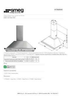
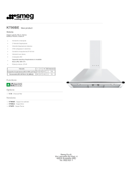
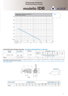
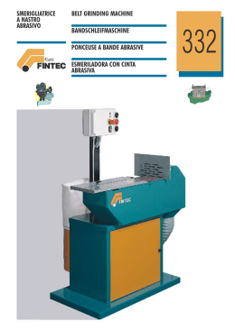
Libretto Istruzioni
IT
Istruzioni per l’istallazione, l’uso, la manutenzione
Instruction manual
Instructions for installation, use and maintenance
OFF
AUT
GB
2
IT
Fig 1
AVVERTENZE
-
-
-
-
-
Prima di usare il nuovo apparecchio, leggete attentamente le istruzioni dell’uso. Esse contengono
informazioni importanti per la Vostra sicurezza ed
anche per la manutenzione dell’apparecchio.
La cappa aspirante è conforme alle norme di sicurezza.
Le riparazioni devono essere eseguite solo da personale autorizzato.
L’apparecchio non è destinato ad essere usato da persone (bambini compresi) le cui capacità fisiche, sensoriali o mentali, siano
ridotte, oppure con mancanza di esperienza o di conoscenza, a
meno che esse abbiano potuto beneficiare, attraverso l’intermediazione di una persona responsabile della loro sicurezza, di una
sorveglianza o di istruzioni riguardanti l’uso dell’apparecchio.
La cappa aspirante può essere utilizzata per il funzionamento ad
espulsione d’aria ed a ricircolo d’aria.
Montare la cappa aspirante sempre centrata sopra il piano di cottura.
Se le istruzioni di installazione del dispositivo di cottura a gas,
indicano che è necessaria una distanza maggiore di 65 cm fra
i fornelli elettrici ed il bordo inferiore della cappa aspirante, è
fondamentale tenerne conto.
Sopra un focolari per combustibili solidi, dal quale può derivare
un pericolo d’incendio (es. scintille), il montaggio della cappa
aspirante è consentito solo se il focolare è dotato di una copertura chiusa non smontabile e se contemporaneamente vengono
osservate le pertinenti norme nazionali.
Questa limitazione non è valida per le cucine a gas e per i piani
cottura a gas.
Non usare mai la cappa aspirante senza filtro.
x6
Y
x6
Z
x2
D
C
A
DESCRIZIONE KIT
A
B
C
D
-
-
X
B
AVVERTENZE PER APPARECCHI DI COTTURA A GAS
-
E
Nel montaggio dei fornelli a gas non usare tutti i
fornelli contemporaneamente al massimo carico
termico per un periodo prolungato (max. 15 minuti), altrimenti sussiste il pericolo di scottature,
se si tocca la superficie dell’involucro o pericolo
di danni alla cappa aspirante.
Nell’uso della cappa aspirante sopra un piano di cottura a gas,
i caso d’utilizzo contemporaneo di tre o più fornelli, la cappa
aspirante deve funzionare al massimo dell’aspirazione.
Distanza minima per i fornelli a gas fra bordo superiore della
griglia di appoggio pentole e bordo inferiore della cappa aspirante 650 mm.
Cappa aspirane
Staffa a parete
Proluga camino
Camino
E
X
Y
Z
Staffa camino
Vite a muro
Stop per muro
Vite camino
Fig 2
A
SMALTIMENTO RIFIUTI
-
-
Questa direttiva definisce le norme per la raccolta
ed il riciclaggio degli apparecchi dismessi valide
su tutto il territorio dell’Unione Europea.
Questo apparecchio dispone di contrassegno ai sensi della
direttiva europea 2002/96/CE in materia di apparecchi elettrici
ed elettronici (waste electrical and eletronic equpment - WEEE).
MONTAGGIO DELLA CAPPA ASPIRANTE
Per il corretto montaggio della cappa aspirante alla parete seguire le
istruzioni:
1 Posizionare la staffa A sulla parete effettuando i quattro fori previsti,
quindi fissarla con le viti X e gli stop Y forniti in dotazione (fig.2).
ALLACCIAMENTO ELETTRICO
Fig 3
Per il collegamento diretto alla rete, è necessario prendere un dispositivo
che assicuri la disconnessione dalla rete, con una distanza di apertura dei
contatti che consenta la disconnessione completa nelle condizioni della
categoria di sovratensione III, conformemente alle regole di installazione.
La spina deve essere accessibile dopo l’installazione.
ATTENZIONE! Se il cavo di alimentazione viene danneggiato
per la sua sostituzione rivolgersi alla casa costruttrice oppure a personale tecnico autorizzato. La cappa è conforme
alle norme CEE sulla schermatura contro i radio disturbi.
ATTENZIONE! Se la sensibilità del Touch-Screen risultasse
bassa, invertire la polarità di alimentazione (girare la
spina o invertire i cavi BLU-MARRONE sulla morsettiera
di collegamento alla rete elettrica).
B
X
A
2 Posizionare la cappa agganciandola alla staffa A precedentemente
istallata, quindi regolarne la centratura sopra la cottura, quindi fissarla
conle viti X (fig.3)
A+A02
3
IT
A questo punto si può procedere al montaggio del camino:
1 Posizionare la parte del caminoC alla cappa, fissandolo con le vitiZ
forniti in dotazione (fi
g.4).
Fig 4
Fig 6
E
X
FUNZIONAMENTO
- a scarico d’aria:
L’aria non deve essere scaricata in un condotto utilizzato per evacuare i
fumi di scarico prodotti da combustione di gas o altri combustibili (non
si applicano agli apparecchi che si limitano a scaricare nuovamente
l’aria nel locale).
Quando la cappa da cucina funziona contemporaneamente ad altri apparecchi che non sono alimentati con elettricità, la pressione negativa
del locale non deve superare i 4 Pa (4x10⁻⁵ bar).
Il locale deve disporre di suffi
ciente ventilazione quando la cappa di cucina è utilizzata contemporaneamente ad altri apparecchi che impiegano
gas o altri combustibili (non si applica agli apparecchi che si limitano a
scaricare nuovamente l’aria nel locale).
Se l’aria di alimentazione non è sufficiente, sussiste pericolo d’ intossicazione a causa di ritorno di gas combusti.
Una cassetta murale di alimentazione/scarico dell’aria da sola non
garantisce il rispetto del valore limite.
C
A
OFF
AUT
Nota: Nella stima si deve considerare sempre il bilancio totale
dell’areazione dell’abitazione. Questa regola non si applica per
il funzionamento di apparecchi di cottura, p. es. piano di cottura
e cucina a gas.
2 Posizionare la
E all’altezza desiderata tramite le apposite viti
Se la cappa aspirante viene usata in funzionamento a ricircolo d’aria X e gli stop Y forniti in dotazione (fi
g.4).
con filtro a carbone attivo -, questo uso è consentito senza limitazioni.
Fig 5
- a ricircolo d’aria con fi ltro a carboni attivi:
Z
E
A questo scopo è necessario montare un filtro a carbone attivo (vedi
capitolo “Filtri e manutenzioni”).
Potete acquistare presso il fornitore specializzato il set di montaggio
completo ed i filtri di ricambio.
D
La ventola della cappa aspirante aspira vapori di cottura, li invia attraverso il filtro anti grasso ed il filtro a carbone attivo e li immette di
nuovo depurati nella cucina. Il filtro trattiene i componenti grassi dei
vapori di cottura.
C
Il filtro a carboni attivi fissa gli odori.
Se non si monta un filtro a carbone attivo, non possono essere fissati
gli odori dei vapori di cottura.
AVVIAMENTO
FUNZIONAMENTO GENERALE
Scheda elettronica gestisce il funzionamento della cappa aspirante.
Agendo sui tasti di tipo “Touch” è possibile: accendere e spegnere i led di
illuminazione, regolare la velocità di aspirazione della cappa (3 possibili
velocità selezionabili) in manuale o in automatico.
OFF
AUT
ACCENZIONE E SPEGNIMENTO LUCE
La scheda elettronica permette l’accensione e spegnimento della luce a led collegata alla scheda per l’illuminazione del piano cottura.
3 Ancorare il caminoD alla
E con le viti Z forniti in dotazione e
sulla parteC ad incastro (fig.5).
ATTENZIONE! Per qualsiasi informazione rivolgersi alla
casa costruttrice.
Per accendere la luce toccare brevemente il tasto con il simbolo relativo nello stesso istante l’emettitore sonoro emette un beep e la luce
si accende.
A+A02
4
IT
1-2-3
REGOLAZIONE DELLA VELOCITÀ DI ASPIRAZIONE
Fig 7
MANUALE
La scheda elettronica permette di regolare in maniera
manuale 3 diverse velocità di aspirazione per la cappa.
Per regolare l’aspirazione alla velocità 1 toccare brevemente il tasto con il simbolo relativo nello stesso istante l’emettitore
sonoro emette un beep, il led 1 si accende (mentre i led 2, led 3 se accesi
si spengono) e la velocità di aspirazione passa a 1 (velocità minima).
Per regolare l’aspirazione alla velocità 2 toccare brevemente il tasto con
il simbolo relativo nello stesso istante l’emettitore sonoro emette un
beep, i led 1 e led 2 si accendono (mentre il led 3 se acceso si spegne)
e la velocità di aspirazione passa a 2 (velocità media).
Per regolare l’aspirazione alla velocità 3 toccare brevemente il tasto
con il simbolo relativo nello stesso istante l’emettitore sonoro emette
un beep, i led 1, led 2 e led 3 si accendono e la velocità di aspirazione
PULIZIA DEI FILTRI METALLICI:
passa a 3 (velocità massima).
Il lavaggio può essere effettuato ogni tre mesi ed eseguito nella lavastoPer spegnere l’aspirazione toccare brevemente il tasto con il simbolo
viglie. Nel lavaggio è possibile una lieve alterazione del colore. Quando
relativo nello stesso istante l’emettitore sonoro emette un beep, tutti i
si lavano filtri metallici, pulire anche i depositi di grasso sulle pareti
led si spengono e l’aspirazione si spegne.
accessibili della carcassa.
REGOLAZIONE AUTOMATICA DELLA VELOCITÀ DI
ATTENZIONE! Non lavare i filtri metallici molto sporchi
ASPIRAZIONE IN BASE ALLA TEMPERATURA
insieme alle stoviglie. Per il lavaggio a mano, fare amLa scheda elettronica permette di regolare in maniera
morbidire i filtri grassi per più ore in una soluzione di
automatica 3 diverse velocità di aspirazione per la
lavaggio bollente. Poi spazzolare, sciacquare bene con
cappa in base alla temperatura rilevata dalla sonda di
acqua pulita e fare sgocciolare.
temperatura presente all’interno della cappa aspirante.
Per regolare in maniera automatica, in base alla temperatura, la velocità
SMONTAGGIO E MONTAGGIO DEI FILTRI METALLICI:
di aspirazione, in stato di OFF dell’aspirazione, toccare brevemente il
Premere
le maniglie dei filtri (fig. 7 pos. 1) poi sganciare ruotandoli
tasto con il simbolo relativo nello stesso istante l’emettitore sonoro
emette un beep e il led 4 comincia a lampeggiare secondo la sequenza verso il basso (fig. 7 pos. 2) dopo di che toglierli;
2 lampeggi – pausa - 2 lampeggi - pausa.
- Pulire i filtri (vedi pulizia dei filtri metallici);
Da questo istante la velocità di aspirazione viene automaticamente re-- Inserire di nuovo i filtri facendo le operazioni inverse.
golata dalla scheda elettronica in base alla temperatura percepita dalla
sonda collegata alla scheda secondo la seguente tabella:
PULIZIA FILTRO A CARBONE ATTIVO DOVE
1. Temperatura inferiore a 50C°: Aspirazione OFF;
PREVISTO:
2. Temperatura tra 50°C e 60°C: Velocità 1;
Il lavaggio può essere effettuato ogni tre mesi ed eseguito nella lavastoviglie.
3. Temperatura tra 60°C e 70°C: Velocità 2;
Nel lavaggio è possibile una lieve alterazione del colore.
Temperatura superiore a 70°C: Velocità 3.
Per disabilitare la regolazione automatica dell’aspirazione toccare brevemente il tasto con il simbolo relativo nello stesso istante l’emettitore sonoro emette un beep, ed il led relativonisce
fi di lampeggiare e si spegne.
ATTENZIONE! Per la pulizia ed il montaggio del filtro al
carbone attivo rivolgersi alla casa costruttrice.
TIMER DI SPEGNIMENTO AUTOMATICO
PULIZIA:
La scheda elettronica permette di impostare un timer di
La pulizia della cappa è necessaria per evitare un pericolo d’incendio e
spegnimento automatico aspirazione o luci. Per attivare
per assicurarsi un funzionamento ottimale. Per pulire la cappa aspirante
il timer, toccare brevemente il tasto relativo quando
usare un soluzione di acqua e detersivo ben calda, oppure detergente per
almeno una tra luci e velocità di aspirazione risultano
vetri delicato. Non rimuovere lo sporco secco aderente graffi
andolo, ma
attivate, nello stesso istante l’emettitore sonoro emette un beep e il led
ammorbiditelo con un panno umido. Non usare prodotti abrasivi o spugne.
4 comincia a lampeggiare secondo la sequenza lampeggio – pausa –
lampeggio – pausa.
AVVERTENZA! Non usare alcool (spirito) sulle superfici di
Da questo istante il timer si avvia e trascorsi 15 min. luci e aspirazione
plastica, si potrebbero formare zone opache.
si spengono.
Per disabilitare il timer di spegnimento automatico toccare brevemente
ATTENZIONE! Arieggiare sufficientemente la cucina, non
il tasto con il simbolo relativo nello stesso istante l’emettitore sonoro
usare fiamme libere.
emette un beep, ed il led relativonisce
fi di lampeggiare e si spegne.
ATTENZIONE! A causa della progressiva saturazione con
residui grassi, l’infi ammabilità aumenta e il funzionamento
della cappa aspirante può essere pregiudicato.
ATTENZIONE! Pulendo tempestivamente i filtri metallici si
previene il pericolo d’incendio, che può essere causato da
un accumulo di calore durante la frittura o l’arrosto.
Non preparare alimenti flambè sotto la cappa di cucina.
Pulire i tasti di comando solo con una soluzione di acqua e detersivo
delicato e con panno morbido, umido.
Per i tasti di comando non usare un pulitore per acciaio inox.
SUPERFICI IN ACCIAIO INOX:
Usare detergente per acciaio inox delicato, non abrasivo. Pulire strofinando solo nel senso della lucidature. Non pulire le superfici in acciaio
inox con spugne dure, ne con detergenti contenenti sabbia, soda, acido
o cloruro.
A+A02
5
GB
Fig 1
WARNINGS
-
-
-
-
-
Read the instructions carefully before using your new
appliance. They contain information that is important
for your safety and also for proper maintenance of the
appliance.
This suction hood complies with safety regulations.
Repairs must only be carried out by authorised technicians.
The appliance must not be used by persons (including children)
with limited physical, sensorial or mental abilities, or without the
necessary experience or knowledge, unless they are supervised
by a person responsible for their safety or have been instructed
by that person regarding the use of the appliance.
The suction hood can be used in extraction mode and in filtration
mode.
The suction hood must always be fitted so that it is centred over
the cooker hob.
If the installation instructions for the gas cooker indicate that a
distance of more than 65 cm must be left between the hob and the
lower edge of the suction hood, it is essential that this be complied
with.
Over solid fuel stoves in which there is a risk of fire (e.g. from
sparks) the suction hood is only allowed if the stove is fitted with a
non-removable closed cover and if the relevant national regulations
are also met.
This restriction does not apply to gas hobs and gas cookers.
Never use the suction hood without a filter.
x6
Y
x6
Z
x2
D
C
A
DESCRIPTION OF KIT
A
B
C
D
-
-
X
B
WARNINGS FOR GAS COOKERS
-
E
When fitting gas hobs, do not use all the burners
simultaneously at maximum power for long periods
(max. 15 minutes), otherwise there is a risk of
burning if the surface of the casing is touched or a
risk of damage to the suction hood.
When using the suction hood over a gas hob, the suction hood
must be set to maximum suction power if three or more burners
are being used.
For gas hobs, the minimum distance between the upper edge
of the pan support grill and the lower edge of the suction hood
is 650 mm.
Suction hood
Wall bracket
Chimney extension
Chimney
E Chimney bracket
X Wall screw
Y Wall plug
Z Chimney screw
Fig 2
A
WASTE DISPOSAL
-
-
This directive provides the regulations for collection and recycling of decommissioned appliances
that apply throughout the European Union.
This appliance is marked in accordance with European Directive
2002/96/EC on waste electrical and electronic equipment –
WEEE.
FITTING THE SUCTION HOOD
To fit the suction hood properly to the wall, proceed as follows:
1 Position bracket A on the wall, drilling the 4 holes required, then fix
it using the screws X and wall plugs Y provided (fig.2).
ELECTRICAL CONNECTIONS
Fig 3
For direct connection to the mains it is necessary to provide a cut-out
device with a contact aperture that allows for complete disconnection in
the case of category III power surges, in compliance with the installation
regulations.
The power plug must be accessible after installation.
WARNING! If the power cable is damaged, please contact
the manufacturer or an authorised technician to replace
it. The hood complies with EEC regulations on screening
against radio frequency disturbance.
WARNING! If the Touch-Screen sensitivity is low, reverse
the polarity of the power supply (turn the plug around or
reverse the positions of the BLUE-BROWN cables in the
mains connection terminal board).
B
X
A
2 Position the hood, hooking it to bracket A installed as described
above, then adjust centring over the hob an finally fasten using
screws X (fig.3).
A+A02
6
GB
At this point it is possible to fi
t the chimney:
1 Position partC of the chimney on the hood, fixing it with the screws
Z provided (fig.4).
Fig 4
Fig 6
LUCE
E
X
1
2
3
A
OPERATION
- in extraction mode:
The air must not be extracted into a flue that is also used to for the
exhaust fumes from gas burners or other fuel-burning appliances (this
does not refer to appliances that simply discharge the air back into the
room).
When the cooker hood is working simultaneously with other appliances
that are not powered by electricity, the negative pressure in the room
must not exceed 4 Pa (4x10⁻⁵ bar).
The room must be adequately ventilated when the cooker hood is used
simultaneously with other gas or fuel burning appliances (this does not
refer to appliances that simply discharge the air back into the room).
If the supply of air is insufficient, there is a risk of intoxication by
exhaust fumes.
An air vent in the wall is not suffi
cient to guarantee compliance with
this limit value.
C
A
Note: When making calculations, the total balance of ventilation
within the home must be taken into consideration. This rule does
not apply for operation of cooking appliances, e.g. gas hobs and
cookers.
OFF
AUT
X and wall
2 Position bracketE at the height required using the screws
plugs Y provided (fig.4).
Fig 5
Z
If the suction hood is used in filtration mode – with activated charcoal
filter – there are no limitations to its use.
- in filtration mode with activated charcoal filter:
E
For this type of use it is necessary to fit an activated charcoal filter (see
chapter on “Filters and maintenance”).
The complete assembly kit and sparelters
fi can be purchased from your
specialist supplier.
D
The suction hood fan sucks up cooking fumes, passes them through the
grease filter and the activated charcoallter
fi and then returns the purifi
ed
air to the kitchen. The fi
lter captures the grease in the cooking fumes.
The activated charcoal lter
fi retains smells.
C
If no activated charcoal filter is fitted, the smells present in cooking
fumes will not be retained.
START-UP
GENERAL OPERATION
Operation of the suction hood is managed by a circuit board. Using
the “Touch” type buttons it is possible to: turn the lighting LEDs on
OFF
speeds) in manual or automatic mode.
AUT
TURNING THE LIGHT ON AND OFF
3 Anchor chimneyD to bracket E using the screwsZ provided and
slotting it into partC (fig.5).
WARNING! Please contact the manufacturer for any information you may require.
LUCE
The circuit board allows the LED light connected to the
To turn the light on, touch the button with the relevant symbol briefly.
A beep will sound and the light will turn on.
A+A02
7
GB
1-2-3
MANUAL MODE
Fig 7
The circuit board allows the hood to be set manually to
3 different suction speeds.
To set suction to speed 1, touch the button with the relative symbol briefly. A beep will sound, LED 1 will light
up (while LED 2 and LED 3 will switch off if they are lit) and the suction
speed will switch to 1 (minimum speed).
To set suction to speed 2, touch the button with the relative symbol briefly. A beep will sound, LEDs 1 and 2 will light up (while LED 3 will switch
off if it is lit) and the suction speed will switch to 2 (medium speed).
To set suction to speed 3, touch the button with the relative symbol
briefly. A beep will sound, LEDs 1, 2 and 3 will light up and the suction
speed will switch to 3 (maximum speed).
To turn the suction off, touch the button with the relevant symbol briefl
y.
A beep will sound, all the LEDs will turn off and the suction system will
CLEANING THE METAL GREASE FILTERS:
turn off.
They can be washed once every three months in the dishwasher. They
may change colour slightly during washing. When you wash the metal
grease filters, make sure you also remove the grease deposits from
accessible parts of the hood body.
AUTOMATIC SUCTION SPEED ADJUSTMENT ACCORDING TO TEMPERATURE
WARNING! Do not wash very dirty metal grease filters with
your dishes. To wash by hand, allow the greasy filters to
The circuit board allows the hood to be set automastand for several hours in boiling soapy water to soften
tically to 3 different suction speeds according to the
them. Then brush, rinse thoroughly with clean water and
temperature detected by the temperature probe located
leave to drain.
inside the suction hood itself. To set the suction speed
automatically according to the temperature, with the suction system
set to OFF, touch the button with the relative symbol briefly. A beep will
REMOVING AND REPLACING THE METAL GREASE FILTERS:
sound and LED 4 will start to flash in the sequence 2 flashes – pause - 2
- Press the filter handles (fig. 7 item 1) then disconnect by turning
flashes - pause.
downwards (fig. 7 item 2) and remove them;
From this moment the suction speed will be adjusted automatically by
- Clean the filters (see paragraph on cleaning the metal grease filters);
the circuit board according to the temperature detected by the probe
- Replace the filters by repeating the same operations in reverse order.
connected to the board, based on the following table:
1. Temperature less than 50C°: Suction OFF;
CLEANING THE ACTIVATED CHARCOAL FILTER
2. Temperature between 50C° and 60C°: Speed 1;
WHEN FORESEEN:
3. Temperature between 60C° and 70C°: Speed 2;
It can be washed once every three months in the dishwasher.
Temperature above 70C°: Speed 3.
To disable automatic adjustment of suction speed touch the button withIt may change colour slightly during washing.
the relevant symbol briefl
y. A beep will sound and the relevant LED will
stop flashing and will turn off.
WARNING! Please contact the manufacturer for cleaning
and assembly of the activated charcoal filter.
AUTOMATIC SHUTDOWN TIMER
CLEANING:
The circuit board allows a timer to be set for automatic The hood must be kept clean in order to prevent
refihazards and to ensure
shutdown of the suction system or lights. To activate the proper operation. Clean the suction hood using a solution of hot water
timer, touch the relevant button briefly when either theand detergent, or a delicate glass cleaning product. Do not remove dried
lights, the suction speed or both are working. A beep dirt by scraping it, but soften it with a damp cloth. Do not use abrasive
will sound and LED 4 will start to flash in the following sequence: flash products or sponges.
– pause – flash – pause.
CAUTION! Do not use alcohol (methylated spirits) on plastic
From this moment the timer starts, and after 15 minutes the lights and
surfaces, as this might create opaque areas.
suction system switch off.
To disable the automatic shutdown timer touch the button with the reWARNING! Always keep the kitchen adequately ventilated,
levant symbol briefl
y. A beep will sound and the relevant LED will stop
do not use live flames.
flashing and will turn off.
WARNING! As it gradually becomes saturated with grease,
the level of flammability increases and operation of the
suction hood may become less efficient.
WARNING! Cleaning the metal grease filters at the proper
times prevents the risk of fire that may be caused by an
accumulation of heat when frying or roasting.
Do not flambé food under the cooker hood.
Only clean the control buttons using a solution of water and delicate
detergent on a soft, damp cloth.
Do not use stainless steel cleaners on the control buttons.
STAINLESS STEEL SURFACES:
Use a delicate, non abrasive stainless steel cleaner. When cleaning,
always rub along the grain of the finish. Do not clean stainless steel
surfaces using hard sponges, or detergents that contain sand, soda,
acid or chloride.
A+A02
Scarica