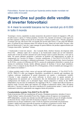
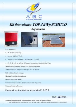
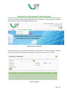
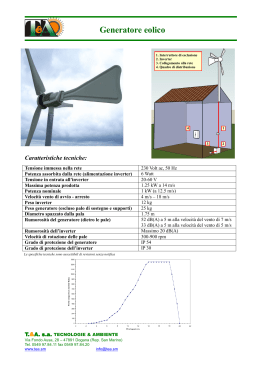
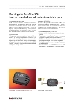
Cod.953906 PHOTOVOLTAIC INVERTER INVERTER FOTOVOLTAICI INSTRUCTION MANUAL • USER.................................................. 3 • SKILLED TECHNICIAN................... 11 MANUALE D’ISTRUZIONE • UTENTE........................................... 27 • TECNICO SPECIALIZZATO............ 35 -1- GB EXPLANATION OF DANGER, MANDATORY AND PROHIBITION SIGNS. I LEGENDA SEGNALI DI PERICOLO, D’OBBLIGO E DIVIETO. (GB) DANGER OF ELECTRIC SHOCK. (I) PERICOLO SHOCK ELETTRICO. (GB) GENERAL HAZARD. (I) PERICOLO GENERICO. (GB) CLASSIFICATION OF THE ELECTRICAL COMPLIANCE OF THE MACHINE. (I) CLASSIFICAZIONE DI COMPATIBILITÀ ELETTRICA DELL’APPARECCHIO. (GB) WARNING! BEFORE USING THE INVERTER READ THE INSTRUCTION MANUAL CAREFULLY! (I) ATTENZIONE! PRIMA DI UTILIZZARE L’INVERTER LEGGERE ATTENTAMENTE IL MANUALE DI ISTRUZIONE! -2- ENGLISH USER INSTRUCTION MANUAL INDEX page 1. SAFETY INSTRUCTIONS ...............................................................................................................................................4 2. PRODUCT DESCRIPTION ..............................................................................................................................................4 2.1 Introduction..................................................................................................................................................................4 2.2 Description of the inverter...........................................................................................................................................4 2.3 Control panel...............................................................................................................................................................4 2.4 Rating plate.................................................................................................................................................................5 2.5 Protection devices.......................................................................................................................................................5 2.5.1 Anti-Islanding......................................................................................................................................................5 2.5.2 Panel grounding fault (insulated PV modules)...................................................................................................5 2.5.3 Fuse checks (grounded PV modules)................................................................................................................5 2.5.4 Other protection devices....................................................................................................................................5 3. OPERATING CONDITIONS..............................................................................................................................................5 3.1 Start-up phase.............................................................................................................................................................5 3.2 Standard operating mode............................................................................................................................................6 3.3 Night-time operations..................................................................................................................................................6 3.4 Malfunction warning messages...................................................................................................................................6 3.5 Alarm warning messages............................................................................................................................................7 4. NAVIGATION THROUGH MENU LEVELS.......................................................................................................................7 4.1 Introduction..................................................................................................................................................................7 4.2 STATISTICS................................................................................................................................................................7 4.2.1 TOTAL................................................................................................................................................................ 7 4.2.2 TODAY............................................................................................................................................................... 8 4.2.3 YESTERDAY......................................................................................................................................................8 4.2.4 CURRENT MONTH............................................................................................................................................8 4.2.5 PREVIOUS MONTH..........................................................................................................................................8 4.2.6 CURRENT YEAR...............................................................................................................................................8 4.2.7 PREVIOUS YEAR..............................................................................................................................................8 4.2.8 EXPORT DATA...................................................................................................................................................9 4.3 SETTINGS..................................................................................................................................................................9 4.3.1 LANGUAGE.......................................................................................................................................................9 4.3.2 DATE/HOUR......................................................................................................................................................9 4.3.3 CURRENCY.......................................................................................................................................................9 4.3.4 KEY BUZZER.....................................................................................................................................................9 4.3.5 ALERTS BUZZER..............................................................................................................................................9 4.3.6 ADDRESS..........................................................................................................................................................9 4.4 INFORMATION.........................................................................................................................................................10 4.4.1 COMPANY.......................................................................................................................................................10 4.4.2 FIRMWARE .....................................................................................................................................................10 4.4.3 LIST ALARM.....................................................................................................................................................10 4.4.4 RESET:............................................................................................................................................................. 10 INSTRUCTION MANUAL FOR THE SKILLED TECHNICIAN................................................. 11 TO KEEP THESE INSTRUCTIONS IN A SAFE PLACE. THEY HAVE TO BE ALWAYS AVAILABLE. -3- 1. SAFETY INSTRUCTIONS These instructions contain information on how to use this photovoltaic inverter. modules realised on circuit boards optimised to achieve maximum reliability and performance (Fig. B). Fig. B AURUS 20, 30, 40, 50 • The device and power lines use voltages that are hazardous and can lead to fatal injuries. • Only qualified operators are permitted to access the connection cabinet. • The inverter must be installed by a specialized technician who is responsible for ensuring conformity with all the rules and regulations in force. • Even when the device is not connected to the mains, there may be high contact voltage still present. • This device must only be used for its intended use. • Check that the insulation on the cables is not worn or damaged. • All maintenance work must be performed at authorized service centers only. PV+ DC 1 INPUT 2 3 4 5 AC OUTPUT PV- 6 DISPLAY AURUS 62, 82 DC INPUT 1 1 PV+ DC INPUT 1 2 PV+ 2 3 4 5 2 3 4 5 PV- PV- 6 Class B device: This inverter meets all emission requirements relating to domestic, industrial environments and those connected directly to a low voltage power supply network that furnishes buildings designated to domestic use. DISPLAY Description: 1. DC input line from the photovoltaic panels. 2. MPPT Card (Maximum Power Point Tracker). It extracts the maximum power possible from the photovoltaic panels according to the current irradiation and turns the DC current into high frequency AC voltage. 3. The high frequency (and high efficiency) transformer installed between the input and output allows for galvanic separation between DC and AC currents. This ensures the highest possible safety levels and the possibility to use all types of PV modules. 4. The transformer output voltage is straightened and filtered using inductors and condensers. 5. A DC/AC converter switches the voltage to the power grid frequency. 6. Control panel to view and set operating parameters. 2. PRODUCT DESCRIPTION 2.1 Introduction AURUS series inverters are devices that are able to convert direct current (DC) generated by photovoltaic panels into alternating current (AC) and to deliver it to the power grid via electricity meters (Fig. A). It is not possible to produce power independently outside the national power grid. The inverter works completely automatically. The entry process begins in the morning as soon as there is sufficient light, and therefore a certain minimum voltage to turn on the inverter. In the evening, when the voltage is below the preset minimum threshold, delivery to the power grid ends and the inverter disconnects from the network. Fig. A 2.3 Control panel Fig. C 1 10 POWER USB WARNING 9 1 2 3 AC OUTPUT ALARM ESC UP DOWN ENTER 8 7 6 5 2 3 4 4 1 PV modules 2Aurus 3Meter 4 Public power grid 2.2 Description of the inverter The inverter consists of a combination of power and control -4- 1. Alphanumeric display. 2. Green LED (POWER): when ON the inverter is working properly; when blinking it is waiting to be connected to the network. 3. Yellow LED (WARNING): OFF by default. When ON it indicates a malfunction. 4. Red LED (ALARM): OFF by default. When ON it indicates an alarm. 5. ENTER button: Press to validate a selection. 6. DOWN button: Press to move onto the next row or choice. 7. UP button: Press to move back to the previous row or choice. 8. ESC button: Press this button to return to the previous menu. 9. USB socket for PC connections. 10.USB socket for pen drives. from the mains. The power grid is monitored by measuring voltage and frequency readings. The inverter is equipped with anti-island protection that is in compliance with local laws. 2.5.2 Panel grounding fault (insulated PV modules) The inverter is fitted with a circuit to measure the grounding insulation resistance. If it drops below a preset value, the inverter is disconnected from the network 2.5.3 Fuse checks (grounded PV modules) The inverter is fitted with a circuit that checks the integrity of the fuse that grounds the positive (or negative) poles of PV modules. 2.4 Rating plate The main inverter performance data is summarised on the rating plate with the following explanations. Fig. D www.valenia.com INPUT 1 VDC max: HF V IDC max: A PDC max: W IAC max: 2 4 7 V 8 3. OPERATING CONDITIONS 3.1 Start-up phase Check that the DC side circuit breaker switch (relative to the photovoltaic panels) is set to ON. Check that all the network side switches (magneto thermal and/or differentials) are set to ON. When there is insufficient sunlight, the inverter will switch off. OUTPUT VAC nom: 1/N/PE AC 230 V / 50 Hz 1 3 6 Type: N. VDC MPPT: 2.5.4 Other protection devices The inverter is fitted with the following protection devices: • Varistor test. • Condenser test. • Internal temperature test. • Relay contact test. • Operating settings test. P nom: 50 Hz cos. φ: A W 9 1 EN IP PROTECTIVE CLASS I 10 5 1. Symbol of the internal structure of the inverter. 2. EU reference standard for the safety and construction of the inverter. 3. Protection ratings of the casing. 4. Protection class I: Equipment where protection against electric shock does not rely solely on basic insulation, but includes an additional safety precaution, consisting of devices which connect masses to the systems grounding system. 5. CE Marking: This inverter meets the basic requirements foreseen by the EMC (2004/108/EC) and LVD (2006/95/ EC) Directives. 6. Inverter name 7. Serial number to identify the inverter (essential for technical assistance, spare part requests, tracing of product origin). 8. DC input technical features: • VDC MPPT : MPPT voltage range. • VDC max: Maximum input voltage (calculated as the minimum temperature the FV modules can reach with an irradiation level of 1000W/m2). • IDC max: maximum input current. • PDC max: maximum input power. 9. DC output technical features: • VAC nom: nominal mains voltage. • IAC max: maximum output current. • PAC nom: nominal output power. • cos φ: power factor. 10. Electrocution hazard, read the instruction manual carefully. 2.5 Protection devices 2.5.1 Anti-Islanding In cases of abnormal behaviour by the power grid, the inverter will stop operations immediately and disconnect When sunlight is sufficient, the inverter will switch on and commence the start-up phase. The inverter tests the level of insulation between the DC side (panels) and the ground. LED Power: Blinking The inverter will then run a series of internal check tests. LED Power: Blinking Before connecting up, the inverter will run a voltage and frequency grid test. They need to be withing the preset thresholds by at least 30s. If they are within the set thresholds, the message OK will appear. From this moment on, starts the gradual delivery of power to the grid up to the maximum available power. -5- • Pac: Instant value of power delivered to the power grid. • F: Instant value of network frequency. • Vacm: Average value of the mains voltage calculated over the last 10 minutes of inverter operation. If check test results are not positive, the inverter will attempt to connect until all the network settings (voltage and frequency) are within the required thresholds. Information on production/absorption of reactive power; • Qac max: Reactive power (var). -if this is positive, the generator provides a reactive power to the grid by delivering a delayed current in respect to the voltage (generator behaviour: overexcited or capacitive). The inverter will support a supply voltage at the grid connecting point; - if this is negative, the generator absorbs the reactive power from the grid by delivering current in advance in respect to the voltage (generator behaviour: underexcited or inductive). The inverter will limit the supply voltage at the grid connecting point; • cosphi: phase shift between voltage and current delivered. Note: The normal condition of operation of the inverter provides a single injection of the active power with cosphi=1 and Qac=0 var. Page 4 3.2 Standard operating mode When operating in standard mode, the Power LED is ON and the main inverter operating settings will be displayed on various pages on the screen. Press the UP or DOWN button to move from page to page. Page 1 Page 5 Inverter information: • Inverter name. • Firmware Version. • Inverter status: OK (or WARNING). • Date/time and page number. Information on production of energy; • Pac max: Maximum power reached during the day. • E-day: Amount of energy generated during the day. • E-tot: Total energy generated since installation. • h-tot: Device operating hours. NOTA: Operations are guaranteed even in WARNING situations. To find out more about a malfunction, please refer to chap.3.4. Page 2 3.3 Night-time operations The information is displayed regardless of whether the inverter is running or not. It is therefore possible to query the system for daily data, statistics etc, even after sunset. Press any button to switch on the display. When sunlight is not sufficient to deliver energy to the power grid, the inverter will remain in stand-by mode: 3.4 Malfunction warning messages If a malfunction occurs, the yellow “WARNING” LED comes ON. The inverter will not shut down the delivery of energy to the power grid. It is however recommended to run a check test according to the error message on the display to avoid possible damage. The malfunction description will appear on the display in alternation to the selected page. The device will buzz every 10s until silenced by pressing the “ESC” button. To silence it completely, see Chap. 4.3.5 (not a recommended choice). Information on the DC side (panels) • Vpv: Instant value of input voltage. • Ipv: Instant value of input current. • Ppv: Instant value of input power. NOTE: in case of inverter with 2 MPPT each page will refer to a DC input. Page 3 Information on the AC side (power grid) • Vac: Instant value of power grid voltage. • Iac: Instant value of current delivered to the power grid. -6- WARNING ON THE DISPLAY TYPE OF MALFUNCTION RESOLUTION If the PV modules generate too much power, the inverter will self-limit delivery to the maximum power allowed. This could occur at around midday in case a PV generator is oversized. If the PV modules generate too much current, the inverter will self-limit delivery to the maximum current allowed. If the malfunction persists, contact the system installers. The temperature inside the device is too high. The inverter has reduced power to prevent damage. Check that sufficient heat dissipation is provided. If the malfunction persists, contact the system installers. The main frequency is higher than the preset threshold. The inverter limits the delivery of the active power according to a preset curve. If the malfunction persists, contact the network operator. Check the varistors. The varistors may be worn. Contact the system installer. Check the condensers. The condensers may be worn. Contact the system installer. Derating P Derating I Derating T Derating f USB flash driver USB not working. error. No Network ALARM_14 Network over-voltage ALARM_15 Network under-voltage ALARM_16 Over frequency ALARM_17 Under frequency ALARM_18 Output over-current ALARM_19 Bonded relay ALARM_20 ALARM_50 HF transformer over-current (MPPT 1) HF transformer over-current (MPPT 2) ALARM_21 DC component over-current (MPPT 1) ALARM_22 ALARM_52 MPPT stop (MPPT 1) MPPT stop (MPPT 2) ALARM_23 Faulty PV module fuse ALARM_24 Average value of the mains voltage that exceeds the limit. If an alarm cuts in the inverter switches off and then tries to restart automatically. If the alarm persists contact the system installer. PLEASE NOTE: In ALARM_3 type cases (Grounding insulation fault), the problem can be caused by a fault in insulation between the PV panels and the ground. This can be caused by infiltration of humidity on the panels due to condensation. If this problem occurs frequently, contact the system installers for a check test. If the inverter does not reconnect to the network, (even when rebooting the DC power supply) place the unit in safety mode by opening the upstream DC switch and the magneto thermal switch downstream of the device. Contact the system installer. Replace USB. 3.5 Alarm warning messages If a malfunction occurs, the red “ALARM” LED turns ON. Immediately, the inverter will shut down the delivery of energy to the power grid and the alarm description will appear on the display. A buzzer will also go off every 3s until silenced by pressing the “ESC” button. To silence it completely, see Chap. 4.3.5 (this is not a recommended choice). WARNING ON THE DISPLAY ALARM_13 4. NAVIGATION THROUGH MENU LEVELS 4.1 Introduction Press the “ESC” button to access the following menus: Press the UP or DOWN button to move from line to line. Press the ENTER key to access to the sub-menu selected. Pressing the “ESC” button to move back a level. TYPE OF FAULT ALARM_1 ALARM_31 Panel voltage too high (MPPT 1) Panel voltage too high (MPPT 2) ALARM_2 ALARM_32 BUS voltage exceeds thresholds (MPPT 1) BUS voltage exceeds thresholds (MPPT 2) ALARM_3 Grounding insulation fault ALARM_4 ALARM_34 Main dissipator overheated (MPPT 1) Main dissipator overheated (MPPT 2) ALARM_5 ALARM_35 Synchronism error (MPPT 1) Synchronism error (MPPT 2) ALARM_6 ALARM_36 Secondary dissipator overheated (MPPT 1) Secondary dissipator overheated (MPPT 2) ALARM_7 Communication error ALARM_8 ALARM_38 NTC error (MPPT 1) NTC error (MPPT 2) ALARM_9 Hardware fault ALARM_10 ALARM_40 Communication error (MPPT 1) Communication error (MPPT 2) ALARM_11 No threshold ALARM_12 DSP Error 4.2 STATISTICS Select “STATISTICS” to view the following sub-menu: Press the UP or DOWN button to move from line to line. Press the ENTER key to access to the sub-menu selected. Pressing the “ESC” button to move back a level. -7- 4.2.1 TOTAL Select “TOTAL” to view the following information: • • • • • E-tot: Total energy generated since installation. h-tot: Device operating hours. Ppk: Peak power since the device was installed. Earnings. CO2: Drop in CO2 emissions since installation. • Earnings gained during the current month. • CO2: Drop in CO2 emissions during the current month. 4.2.5 PREVIOUS MONTH Select “PREVIOUS MONTH” to view the following information: • E-monthP: Amount of energy generated during the previous month. • h-monthP: Device operating hours during the previous month. • Ppk: Peak power during the previous month. • Earnings gained during the previous month. • CO2: Drop in CO2 emissions during the previous month. 4.2.2 TODAY Select “TODAY” to view the following information: • E-day: Amount of energy generated during the current day. • h-day: Device operating hours during the current. • Ppk: Peak power during the current day. • Earnings gained during the current day. • CO2: Drop in CO2 emissions during the current day. 4.2.6 CURRENT YEAR Select “CURRENT YEAR” to view the following information: • E-year: Amount of energy generated during the current year. • h-year: Device operating hours during the current year. • Ppk: Peak power during the current year. • Earnings gained during the current year. • CO2: Drop in CO2 emissions during the current year. 4.2.3 YESTERDAY Select “YESTERDAY” to view the following information: • E-dayP: Amount of energy generated during the previous day. • h-dayP: Device operating hours during the previous day. • Ppk: Peak power during the previous day. • Earnings gained during the previous day. • CO2: Drop in CO2 emissions during the previous day. 4.2.4 CURRENT MONTH Select “CURRENT MONTH” to view the following information: • E-month: Amount of energy generated during the current month. • h-month: Device operating hours during the current month. • Ppk: Peak power during the current month. -8- 4.2.7 PREVIOUS YEAR Select “PREVIOUS YEAR” to view the following information: • E-yearP: Amount of energy generated during the previous year. • h-yearP: Device operating hours during the previous year. • Ppk: Peak power during the previous year. • Earnings gained during the previous year. • CO2: Drop in CO2 emissions during the previous year. appear on the display: from there you can set the date and time. Press ENTER and then the UP or DOWN button to increase or decrease the selected digit, then press ENTER to confirm the value. 4.3.3 CURRENCY Selecting “CURRENCY” will make the following sub-menu appear on the display: from there you can set the currency of your choice (by default, “EUR”). Press ENTER and then the UP or DOWN button to increase or decrease the selected digit, then press ENTER to confirm the value. 4.2.8 EXPORT DATA By using an USB flash drive fit in the inverter, the following actions are possible: • INTERNAL DATA export the data stored in the internal memory. • DATALOGGER use the USB flash drive as a data logger. In this mode, you can save information on the operation of the inverter with a recording interval that can be set. For more information on the export of data refer to the website of Valenia (www.valenia.com). The incentive rate (€ / kWh) must be entered in the VAL/ kWh field which by default is set to 0.30 € / kWh. Press ENTER and then the UP or DOWN button to increase or decrease the selected digit, then press ENTER to confirm the value. 4.3 SETTINGS Press the “ESC” button to access the following menus: Press the UP or DOWN button to move from line to line. Press the ENTER key to access to the sub-menu selected. Press the “ESC” button to move back a level. 4.3.4 KEY BUZZER Selecting “KEY BUZZER” will make the following sub-menu appear on the display: from there you can enable or disable key sounds: ON: key sounds are enabled. OFF: key sounds are disabled. Press ENTER to confirm the value. Select “SETTINGS” from the main menu to view the following sub-menu: Press the UP or DOWN button to move from line to line. Press the ENTER key to access to the sub-menu selected. Press the “ESC” button to move back a level. 4.3.5 ALERTS BUZZER Selecting “ALERTS BUZZER” will make the following sub-menu appear on the display: from there you can disable malfunction or fault alarm tones permanently (not recommended). ON: alarm buzzer is enabled. OFF: alarm buzzer is disabled. Press ENTER to confirm. 4.3.1 LANGUAGE Select “LANGUAGE” from the display to make the following sub-menu appear on the display: from there you can choose your preferred language. Press ENTER to confirm the choice made. 4.3.2 DATE/HOUR Selecting “DATE/HOUR” will make the following sub-menu 4.3.6 ADDRESS Use this function to set the address of each inverter (useful for distinguishing the individual inverters if more than one unit has been installed in the same system). The numbers from 1 to 32 can be assigned. -9- 4.4.4 RESET: Select “ALARM RESET” then ON to reset all the alarms. 4.4 INFORMATION Press the “ESC” button to access the following menus: Press the UP or DOWN button to move from line to line. Press the ENTER button to access to the submenu selected. Press the “ESC” button to move back a level. Select “INFORMATION” from the main menu to view the following submenu: Press the UP or DOWN button to move from line to line. Press the ENTER button to access to the submenu selected. Press the “ESC” button to move back a level. 4.4.1 COMPANY Select “COMPANY” to view information on the inverter manufacturer. 4.4.2 FIRMWARE Selecting “FIRMWARE” will make the following sub-menu appear on the display with information on the software installed. 4.4.3 LIST ALARM Selecting “LIST ALARM” will make the following sub-menu appear on the display with information on the last 9 alarms triggered by the device. Alarm code information is provided in Chap. 3.5. Select the alarm and press the ENTER key to return to the protection intervention date/time. Press the ESC key to return to the original display. - 10 - ENGLISH INSTRUCTION MANUAL FOR THE SKILLED TECHNICIAN INDEX page 1. SAFETY INSTRUCTIONS..............................................................................................................................................12 2. INSTALLATION...............................................................................................................................................................12 2.1 Photovoltaic generator project (PV modules)............................................................................................................12 2.1.1 Type of panels used.........................................................................................................................................12 2.2 Selecting the installation location..............................................................................................................................12 2.3 Wall mounting............................................................................................................................................................13 2.4 Electrical connection.................................................................................................................................................14 2.4.1 Introduction......................................................................................................................................................14 2.4.2 Connecting the AC side....................................................................................................................................14 2.4.3 Connecting the DC side...................................................................................................................................14 2.4.4 Connecting with embedded conductors...........................................................................................................15 3. COMMISSIONING...........................................................................................................................................................16 3.1 First Start-Up.............................................................................................................................................................16 4. NAVIGATION THROUGH MENU LEVELS.....................................................................................................................16 4.1 Introduction................................................................................................................................................................16 4.2 MAINTENANCE........................................................................................................................................................16 4.2.1 SELF-TEST......................................................................................................................................................16 4.2.1.1 Vac MAX TEST (59.S2).......................................................................................................................17 4.2.1.2 Vac MEAN TEST (59.S1).....................................................................................................................17 4.2.1.3 Vac MIN TEST (27.S2).........................................................................................................................17 4.2.1.4 Vac MIN TEST (27.S1).........................................................................................................................17 4.2.1.5 TEST F MAX (81>S1)..........................................................................................................................18 4.2.1.6 TEST F MIN (81<S1)...........................................................................................................................18 4.2.1.7 F MAX TEST (81>S2)..........................................................................................................................18 4.2.1.8 F MIN TEST (81<S2)...........................................................................................................................18 4.2.1.9 REMOTE TRIP TEST..........................................................................................................................18 4.2.2 THRESHOLD MODIFICATION........................................................................................................................18 4.2.2.1 START UP THRESHOLD....................................................................................................................19 4.2.2.2 STEADY STATE THRESOLDS AND LOCAL CONTROL....................................................................19 4.2.3 MPPT .............................................................................................................................................................. 19 4.2.4 Panel Insulation................................................................................................................................................19 4.2.5 Changing the password...................................................................................................................................20 4.2.6 Restart default..................................................................................................................................................20 4.2.7 FW release.......................................................................................................................................................20 4.2.8 UP_GRADE FW...............................................................................................................................................20 4.2.9 ACTIVE POWER LIMITATION (Pac)................................................................................................................20 4.2.9.1 Pac=f(F)...............................................................................................................................................20 4.2.9.2 SET POINT Pac ..................................................................................................................................20 4.2.10 REACTIVE POWER INPUT Qac...................................................................................................................21 4.2.10.1 SET POINT cos(φ).............................................................................................................................21 4.2.10.2 SET POINT Qac................................................................................................................................21 4.2.10.3 Cos(φ)=f(Pac) ...................................................................................................................................21 4.2.10.4 Qac=f(V) ...........................................................................................................................................22 5. MAINTENANCE AND CLEANING.................................................................................................................................23 5.1 Replacing the varistors..............................................................................................................................................23 5.2 Replacing the electrolytic condenser card.................................................................................................................23 5.3 Replacing the battery................................................................................................................................................23 6. APPENDIXES.................................................................................................................................................................24 6.1 Technical Data...........................................................................................................................................................24 6.2 Accuracy of measured values...................................................................................................................................25 6.3 Declaration of EC Conformity....................................................................................................................................25 6.4 Declaration of protection system test........................................................................................................................25 TO KEEP THESE INSTRUCTIONS IN A SAFE PLACE. THEY HAVE TO BE ALWAYS AVAILABLE. - 11 - 1. SAFETY INSTRUCTIONS These instructions provide information on: • installation; • commissioning; • maintenance; These operations must only be performed by operators holding suitable qualifications and who have read and fully comprehended the instruction manual. Moreover: • Carry out state of the art electric installation, respecting all the local laws and what is indicated in the EN 50178 directive. • All electrical installations must be performed in accordance with all applicable accident prevention and safety rules and regulations. • The inverter must only be connected to a power supply system with a grounded neutral conductor. • Only qualified operators are permitted to access the connection cabinet. Before opening the cabinet, check that all power has been disconnected to the panel side (DC) and the net side (AC). Before working on the connections, wait for at least 5 minutes to allow the condensers to discharge completely. • This device must only be used for its intended use. • Do not install the device in damp or wet places or in the rain. • Do not use cables with damaged insulation. • The information in this manual relating to installation, commissioning and maintenance are for qualified technical operators only. An electric shock can be fatal. • Make sure there is sufficient air exchange. • Use the device according to the IP data indicated on the rating plate. Class B device: This inverter meets all emission requirements relating to domestic, industrial environments and those connected directly to a low voltage power supply network that furnishes buildings designated to domestic use. 2. INSTALLATION 2.1 Photovoltaic generator project (PV modules) The choice of PV modules (type, power, number of modules) must be suitable for use with the inverter whose technical specifications are described in chap. 6.1. The inverter can operate on a wide range of input voltages. This makes it possible to use many different types of solar modules. Special attention must be given to the maximum voltage reached by the strings voltage with a maximum radiation of 1000W/m2 at a temperature of -20°C: it must be lower than the maximum VDC Voltage allowed by the inverted (See 6.1). Exceeding this voltage can cause irreparable damage to the inverter. Also check that the minimum string voltage falls within the allowed VDC MPPT range. 2.1.1 Type of panels used The presence of the HF transformer provides galvanic insulation between the panels and the electricity grid. This means that PV modules can be used with solar module grounding of the positive or negative pole. The optional grounding KIT can be installed to use PV modules with grounding of the positive or negative pole. On models AURUS 62 and AURUS 82 it is NOT possible to: • use panels with grounding of the positive pole; • connect in parallel the two MPPT (DC INPUT 1 and DC INPUT 2); • exceed the maximum power foreseen for each MPPT (see table 6.1). 2.2 Selecting the installation location The inverter must be installed in a position that meets the requirements below, hence needing: • solid vertical wall. • height from the floor that makes reading the display easier. • protection against rain and water splashes (IP21). • INDOOR use only . • protection against direct sunlight. • sufficient ventilation. • ambient temperature of between -20°C and +60°C. • relative air humidity (non condensing) from 0 to 95%. • altitude above sea level of up to 2000m. • maintain a minimum clearance space of 200mm on both sides of the inverter and 50mm from the ceiling (Fig. A). • maintain a distance of at least 300mm between each inverter. • an air flow inside the inverter that goes from right to left. If the inverter is assembled inside an electric cabinet or similar, there must be sufficient heat dissipation by means of forced ventilation systems. - 12 - Fig. A Fig. C 50 mm 315mm 1 180mm 200 mm 300 mm 315mm Do not install the inverter in: • places which produce massive amounts of dust (conductive and non-conductive); • places with corrosive fumes, acids or salts; • places storing inflammable substances; • places with explosion risks; 1 348mm 2.3 Wall mounting Remove all packaging carefully, checking the integrity of all parts. Keep all original packaging which can be used if the inverter needs to be sent for repairs. Open the connection housing (Fig. B-1) remove the door panel (Fig B-2) and remove the M6 screws (Fig. B-3) so the inverter is separated from the wall bracket (Fig. B-4). Fig. B 315mm 1 4 515mm 2 1 3 The device must be mounted in a vertical position, as seen in Fig. C. The bracket (Fig. C-1) must be fixed to the wall using the 4 screws and 4 dowels. These are not included in the supplied goods as the appropriate screws depend on the type of wall being used. Position the inverter above the bracket and slide it downwards parallel to the wall until all the connectors click into position on the relative seats. Check that the position is correct and the inverter is parallel to the wall. Try to pull it away from the wall to ensure it is fitted on the brackets correctly. Secure the inverter in place using the M6 screws removed earlier on (Fig. B-3). - 13 - 2.4 Electrical connection 2.4.1 Introduction 2 A typical installation of the inverter foresees a bipolar DC switch for each input string and a magnetic switch between the output and the network grid. The minimum requirements for these devices are indicated in Chap. 6.1. Local regulations may also require the installation of a differential switch on the network grid side. It is recommended to use a Type A differential switch. Surge protectors the DC and AC The installation of surge protectors depends on the area where the facility is located, the length of the plants at risk, the type of installation (land, residential, large roofs), and the presence or absence of lightning rod. It is recommended the use of surge protectors in the DC side (one for each input) and one on the AC in the general electrical panel of low voltage. If the distance between general electrical panel of low voltage and the inverter is >10m, it is advisable to use a second surge protector located near the inverter. 3 All electrical wirings must be performed: • in accordance with all State regulations; • by qualified operators only; • after attaching the inverter to the wall; 2.4.2 Connecting the AC side • disconnect the inverter from the PV generator using the DC circuit breaker and from the power network using a magneto thermal switch. • remove the cable sheath and strip the wires (Fig. D-1). • thread the cable through the cable gland on the bottom side (Fig. D-2). • fix the 3 wires to the terminal making sure PE, N, L are correct (insert a screwdriver in the relative space, insert the wire and then remove the screwdriver) (Fig. D-3). • tighten the cable gland (Fig. D-4). 4 The minimum cable diameters are described in chapter 6.1. Increase the diameter if the cable has to be laid on long sections. Fig. D 1 35mm 15mm 2.4.3 Connecting the DC side • disconnect the inverter from the PV generator using the DC circuit breaker and from the power network using a magneto thermal switch. • staple the positive cable (red) to the connector supplied (Figure E-1). • staple the negative cable (black) to the connector supplied (Fig. E-2). • insert the connectors into their respective sockets (Fig. E-3). - 14 - Fig. E they come from embedded pipes. If this connection method is used, make sure there is insulation between the AC and DC cables (there must be dual insulation). Also fit a corner protector to prevent deterioration of the cables due to friction. 3 Moreover: • eliminate all connectors and cable glands from the bottom of the device. • all holes must be sealed (Fig. G-2). 1 2 The safety of this device is only guaranteed if all the holes on the bottom have been sealed (Fig. G-3). Fig. G 1 1 2 2 • Be careful not to reverse the polarity. The inverter is nevertheless equipped with protection against reverse polarity. • Respect the inputs: DC INPUT 1 (MPPT 1) and DC INPUT 2 (MPPT 2) (Fig. F) (for Aurus 62 and Aurus 82 only). • It is not possible the parallel connection of the two MPPT (for Aurus 62 and Aurus 82 only). • not exceed the maximum power foreseen for each MPPT (for Aurus 62 and Aurus 82 only, see table 6.1). Fig. F DC INPUT 1 IDC max = 16.5A DC INPUT 2 3 AC IDC max = 16.5A 2.4.4 Connecting with embedded conductors. The inverter is fitted with a circuit breaker (Figure G-1) on the back that allows the threading of cables (AC and DC) if - 15 - After completing all connections, close the inverter door panel. Please consult the User Manual for information on STATISTICS, SETTINGS and INFORMATION. 3. COMMISSIONING 3.1 First Start-Up Set the DC side switching device (on photovoltaic panels) to the ON position. Set the AC side switching device to the ON position. 4.2 MAINTENANCE Select “MAINTENANCE” from the main menu to view the first screen which sets the PASSWORD: The default password is 0000. To enter the password: use the UP or DOWN button to select the desired number, press ENTER to confirm the selected number and move on to the next. When the device is first switched on, the following fields will be displayed: LANGUAGE The display shows the following menu where you can select the language. Pressing the UP or DOWN key, you can select the desired language, then press the ENTER button to confirm. After entering the correct password, the menu below will appear on the screen: DATE/TIME The following menu appears on the display where you can set the date and time. Press the UP or DOWN button to increase or decrease the selected number, then press ENTER to confirm the value. CURRENCY The following menu then appears on the display where you can set the currency of your choice (by default, “EUR”). Press ENTER and then the UP or DOWN button to increase or decrease the selected digit, then press ENTER to confirm the value. The incentive rate (€ / kWh) must entered in the VAL/kWh field which by default is set to 0.30 € / kWh. Press ENTER and then the UP or DOWN button to increase or decrease the selected digit, then press ENTER to confirm the value entered. 4. NAVIGATION THROUGH MENU LEVELS 4.1 Introduction Press the “ESC” button to access the following menu: 4.2.1 SELF-TEST During normal operations, the inverter constantly monitors the voltage and electric network frequency. The “AUTOTEST” function verifies the interface protection values and timing, adjusting the voltage and network frequency thresholds according to what is foreseen by the network standard CEI 0-21. Selecting “AUTOTEST” the following sub-menu appears on the display from where you can select the test to be performed: • Maximum voltage control test (59.S2). • Medium voltage control test (59.S1) • Minimum voltage control test (27.S2). • Minimum voltage control test (27.S1). • Maximum network frequency control test. (81>S1). • Minimum network frequency control test. (81<S1). • Maximum network frequency control test. (81>S2). • Minimum network frequency control test. (81<S2). • remote trip control test (Telescatto). Press the UP or DOWN button to move from line to line. Press the ENTER button to access to the submenu selected. Press the “ESC” button to move back a level. - 16 - When the inverter has been restarted and reconnected to the network, you can select the next test (repeat the procedure described in 4.1, 4.2, 4.2.1). 4.2.1.2 Vac MEAN TEST (59.S1) Vac MEAN TEST (59.S1) is running (RUN flashing). On the left side is shown the voltage threshold that is decreased until reaching the measured value. When the test has been completed, the following screen appears on the display: Press the UP or DOWN button to select the type of test, then press ENTER to start the selected test. Note: The network operator usually requires a photographic documentation of the implementation of the self-test. Therefore on the lower side of the inverter there is a label with the serial number (SERIAL NO. XXXXXXXX). Once sticked on the display, this label ensures that the documentation refers exactly to the inverter under test. 4.2.1.1 Vac MAX TEST (59.S2) 4.2.1.3 Vac MIN TEST (27.S2) Vac MAX (59.S2) Test is running (RUN flashing). On the left side is shown the threshold voltage that is decreased until reaching the measured value. When the test has been completed, the following screen appears on the display: Vac MIN TEST (27.S2) is running (RUN flashing). On the left side is shown the voltage threshold that is increased until reaching the measured value. When the test has been completed, the following screen appears on the display: On the left side are shown the value and the time of intervention of the set threshold. On the right side are shown the value of the network parameter, measured at the time of the protection interruption, and the time of actual interruption. 4.2.1.4 Vac MIN TEST (27.S1) On the left side are shown the value of the changed threshold (which has caused the protection interruption) and the time of interruption. On the right side are shown the value of the network parameter measured at the time of the protection interruption, and the time of actual interruption. In a similar way it is possible to carry out all the other tests of the auto-test. The inverter is now disconnected from the network as the interface protection was triggered. The test result will remain on the screen until the ESC button is pressed. Vac MIN TEST (27.S1) is running (RUN flashing). On the left side is shown the voltage threshold that is increased until reaching the measured value. When the test has been completed, the following screen appears on the display: - 17 - 4.2.1.7 F MAX TEST (81>S2) F MAX TEST(81>S2) is running (RUN flashing). On the left side is shown the frequency threshold that is decreased until reaching the measured value. When the test has been completed, the following screen appears on the display 4.2.1.5 TEST F MAX (81>S1) F MAX TEST (81>S1) is running (RUN flashing).On the left side is shown the frequency threshold that is decreased until reaching the measured value. When the test has been completed, the following screen appears on the display: 4.2.1.8 F MIN TEST (81<S2) F MIN TEST (81<S2) is running (RUN flashing).On the left side is shown the frequency threshold that is increased until reaching the measured value. When the test has been completed, the following screen appears on the display: 4.2.1.6 TEST F MIN (81<S1) F MIN TEST (81<S1) is running (RUN flashing).On the left side is shown the frequency threshold that is increased until reaching the measured value. When the test has been completed, the following screen appears on the display: 4.2.1.9 REMOTE TRIP TEST Should any of the “AUTOTEST” procedures give a negative result (FAIL), the inverter cannot reconnect to the network. 4.2.2 THRESHOLD MODIFICATION If you select “EDIT THRESHOLDS” the following submenu will appear where it is possible to select the following thresholds: • START UP THRESHOLD • THRESHOLD ON STEADY STATE - 18 - The steady state thresholds are the thresholds of voltage and frequency that must be verified once the inverter is connected to the network. With UP and DOWN you can select the threshold that needs to be varied and with ENTER key you confirm the choice. 4.2.2.1 START UP THRESHOLD The START-UP thresholds are the thresholds of voltage and frequency that must be checked for a time of 300 seconds before connecting the inverter after the intervention of the interface protection. Only the frequency thresholds are modifiable by the operator: with UP and DOWN you can select the threshold that needs to be varied and with ENTER the command is confirmed. With UP and DOWN you set the new threshold with the ENTER key you confirm the new value. Similarly one can vary the threshold F MIN. SETTING AND ADJUSTMENT OF THE THRESHOLD OF START-UP Protection Setting Adjustment fields Vac MAX 253V fix Step Adjustment - Vac MIN 195V fix - F MAX 50.10Hz 50÷51Hz 50mHz F MIN 49.90Hz 49÷50Hz 50mHz Time 300s 0÷900s 5s Note: If the plant starts in the morning or restarts after a logoff not caused by the intervention of interface protections, the time to check the voltage and frequency within the limits of start-up is limited to 30 seconds. 4.2.2.2 STEADY STATE THRESOLDS AND LOCAL CONTROL With UP and DOWN you set the new threshold and with the ENTER key you confirm the new value. Similarly one can vary the thresholds Vac MIN (27.S1), F MAX (81> S1), F MIN (81 <S1), Vac Mean (59.S1 threshold of the average value of the voltage), Vac MIN2 (27.S2 ), MAX F (81> S2), MIN F (81 <S2). To ensure that the change of the thresholds is effective press ENTER to confirm the entered value, ESC to the next menu and ESC until the restart of the inverter. The setting of local control “LOCAL CONTROL” allows to OFF (default selection) to enable the threshold 81.S2 (threshold frequency “permissive”), while in ON the threshold 81.S1 (threshold frequency “restrictive”) . See ch. 6.5 for the calibration and adjustment of the protection interface. 4.2.3 MPPT Select “MPPT” to view the following sub-menu: • MPPT SCAN (ON/OFF). This is a function used to automatically detect any relative maximums. By default, this function is disabled. • SCAN TIME: This is the time between one SCAN function and another, if enabled. Select ON to access the SCAN TIME function where you can change the time between one SCAN and another. 4.2.4 Panel Insulation Selecting “INSUL. PANELS “the following sub-menu will be displayed: • INSULATED (default setting). • POS- GND: panel positive pole grounded. • NEG- GND: panel negative pole grounded. The optional grounding KIT can be installed when using panels with grounding of the positive or negative poles. NOTE: It is not possible to use panels with grounding of the positive pole by AURUS 62 and AURUS 82. - 19 - 4.2.5 Changing the password Select “NEW PASSWORD” to view the following sub-menu: To set the new password, use the UP or DOWN buttons to set the number you want then press ENTER to confirm the selected number and move on to the next. 4.2.6 Restart default Select “DEFAULT RESTART” to view the following submenu: • OFF • ON Select “ON” to return to the original factory settings. When you start-up again, follow the instructions in 3.1 The default setting exclude both these modes. The activation of one of these settings needs to be agreed with your network operator. 4.2.9.1 Pac=f(F) In this mode, the inverter is to reduce the emission of active power Pac as the frequency increases in an automatic and autonomous way in accordance with a preset characteristic curve (Fig. H). Fig. H Pi/Pn [%] 100 50 0% 4.2.7 FW release Select “FW RELEASE” to view the following sub-menu: • LCD INTERFACE (panel software card). • DSP DC/AC (DC/AC software card). • DSP MPPT 1 (software card DC/DC MPPT 1). • DSP MPPT 2 (software card DC/DC MPPT 2 - for AURUS 62 and 82 only). 47.5 50.0 50.3 51.5 f By selecting “Pac=f(F)” the following sub-menu will be displayed: • F(Pac=0). Frequency at which the Pac is cancelled (see Fig. H) • STATUS (ON/OFF). By default this function is disabled. To enable it (ON) check that all other Pac regulations modes are in OFF. Selecting “LCD INTERFACE”, or “DSP DC/AC” or “DSP MPPT 1 (2)”, another sub-menu is displayed indicating the current version of the selected software. 0< Pi ≤3 3< Pi ≤6 F(Pac=0) 51.5Hz Pi: Global power of the plant Pi>6 Adjustment field 51.0÷53.0Hz 4.2.9.2 SET POINT Pac When in this mode the inverter operates according to a fixed Pac value regardless of the output frequency By selecting “ SET POINT Pac” the following sub-menu will be displayed: • Pac. Percentage of active power in comparison with the inverter rating. V • STATUS (ON / OFF). By default this is disabled. To enable it (ON) check that all other Pac regulations modes are in OFF. 4.2.8 UP_GRADE FW The software can be upgraded from this menu. For further information refer to the FW update in the website of Valenia (www.valenia.com). 4.2.9 ACTIVE POWER LIMITATION (Pac) The inverter are able to limitate the delivery of active power Pac according to the mains frequency or to the Pac SET POINT: • Pac=f(F). • SET POINT Pac. - 20 - 0< Pi ≤3 3< Pi ≤6 Pac % Pi: Global power of the plant Pn: Inverter power Pi>6 100% Pn Adjustment field 0÷100% Pn 4.2.10 REACTIVE POWER INPUT Qac The inverter can deliver/absorb a reactive power in 4 different modes: • SET POINT cos(φ): with constat cos(φ). • SET POINT Qac: with constat n Qac. • cos(φ)=f(Pac): with cos(φ) according to the delivered Pac power. • Qac=f(V): with Qac according to the mains voltage. The default setting exclude all these modes. The activation of one of these settings needs to be agreed with your network operator. The inverter can deliver or absorp reactive power (Fig. I): Fig. I Qac II O-E I 0< Pi ≤3 3< Pi ≤6 cos(φ) 0.98 0.95 Pi: Global power of the plant Pi>6 0.90 Adjustment field 0.86÷1.00 4.2.10.2 SET POINT Qac In this mode the inverter operated according to a fixed value of Qac regardless of the output power (Pac). By selecting “ SET POINT Qac” the following sub-menu will be displayed: • Qac. Percentage of reactive power in comparison with the rated power of the inverter. • Operation: O-E (over-excited) / U-E (under-excited). • STATUS (ON/OFF). By default this function is not activated. To activate it (ON) check that all other adjustment modes of Qac are in OFF position. P Pac U-E III 0< Pi ≤3 3< Pi ≤6 Qac % Pi: Global power of the plant Pn: Power of the inverter IV -Qac In the first quadrant the generator provides reactive power to the network (Qac>0) delivering a delayed current in comparison with the voltage (behaviour of the generator: over-excited O-E: over-excited or capacitive). The inverter helps to support the supply voltage at the network connection point. In the fourth quadrant the generator absorbs reactive power from the network (Qac<0) delivering current in advance in comparison with the voltage (generator behaviour: underexcited U-E: under-excited or inductive). The inverter helps to limit the supply voltage at the network connection point.. Pi>6 48% Pn Adjustment field 0÷60% Pn 4.2.10.3 Cos(φ)=f(Pac) In this mode the inverter must be able to absorb reactive power (Qac<0) automatically and independently according to a pre-set characteristic curve (Fig. L1 Type A curve, Fig. L2 Type B curve). Fig. L1 4.2.10.1 SET POINT cos(φ) In this mode the inveter operates with a cos(φ) fixed value and, according to the output power (Pac) it calculates the reactive power to be delivered to/absorbed by the network. By selecting “ SET POINT cosphi” the following sub-menu will be displayed: • cosphi. Value of the cos(φ) that is to be maintained (see table below). • operation: O-E (over-excited) / U-E (under-excited). • STATUS (ON/OFF). By default this function is not activated. To activate it (ON) check that all other adjustment modes of Qac are in OFF position. - 21 - cosφ 0.9 (0.95*) O-E P 0.2 0.3 0.4 0.5 0.6 0.7 0.8 0.9 1 U-E -Pac A 1 P/Pn B 0.9 (0.95*) C Fig. L2 cosφ O-E 0.9 (0.95*) 0.05 0< Pi ≤3 3< Pi ≤6 Pi>6 Point A 20% Pn Point B 50% Pn Point C 100% Pn Point D 5% Pn Vlock-in 241V Vlock-out 230V cos(φ) 0.95 0.90 Pi: Global power of the plant Pn: Power of the inverter 1 P/Pn U-E 1 0.9 (0.95*) D C By selecting “cosphi=f(Pac)” the following sub-menu will be displayed: • Type A. Type A curve (see Fig. L1) • Type B. Type B curve (see Fig. L2) • Vlock. lock/unlock voltages • Cosphi. Value of the minimum cos(φ) Adjustment field 0÷100% Pn 0÷100% Pn 230÷253V 207÷230V 0.86÷1.00 4.2.10.4 Qac=f(V) In this mode, the inverter must be able to absorb / supply reactive power in an automatic and autonomous way in accordance with a preset characteristic curve (Fig. M1 curve-type a, Fig. M2 curve type b). Fig. M1 V V 2s By selecting “Type a”: • Point A. (see Fig. L1 and table) • Point B. ( see Fig. L1 and table) • Point C. ( see Fig. L1 and table) • STATUS (ON/OFF). By default this function is not activated. In order to activate it (ON) check that all other adjusting modes of Qac are in OFF position. V 1s Q min V 1i V 2i By selecting “Type b”: • Point C. ( see Fig. L2 and table) • Point D. ( see Fig. L2 and table) • STATUS (ON/OFF). By default this function is not activated. In order to activate it (ON) check that all other adjusting modes of Qac are in OFF position. Fig. M2 V V 2s V 1s Q min By selecting “Vlock”: • Vlock-in. Activation voltage of the adjustment for reactive power values greater than 50%Pn (curve type a) or 5%Pn (curve type b) (see Fig L2 and table) • Vlock-out. Deactivation voltage of the adjustment for reactive power values greater than 50%Pn (curve type a) or 5%Pn (curve type b) (see Fig L2 and table). By selecting “Cosphi”: • Cosphi. Value of the cos(φ) (see table). V 1i Q max V 2i By selecting “Qac=f(V)” the following sub-menu will be displayed: • type a. Curve type a (see Fig. M1) • type b. Curve type b ( see Fig. M2) • V. Voltage characterization of the curve • Plock. lock/unlock power - 22 - • Remove the connection cabinet panel. • Remove the front upper and lower sections. • Replace the 4 varistors (on the filter card and on the MPPT card). • Repeat the process in the reverse order. By selecting “type a” or “type b” • STATUS (ON/OFF). By default this function is not activated. In order to activate it (ON) check that all other adjusting modes of Qac are in OFF position. By selecting “V”: • V1s (see Fig. M1 or M2) • V2s (see Fig. M1 or M2) • V1i (see Fig. M1 or M2) • V2i (see Fig. M1 or M2) By selecting “Plock”: • Plock-in. Power of activation of the adjustment in reactive. • Plock-in. Power of deactivation of the adjustment in reactive. 0< Pi ≤3 3< Pi ≤6 V1s V2s V1i V2i Plock-in Plock-out Pi: Global power of the plant Pn: Power of the inverter Pi>6 248V 253V 212V 207V 20% Pn 5% Pn 5.2 Replacing the electrolytic condenser card Condensers are components subject to wear. Therefore it is recommended to replace them every 5 years. The procedure is as follows: • Disconnect the inverter from the PV generator using the DC circuit breaker and from the power network using a magneto thermal switch. • Before working on the connections, wait for at least 5 minutes to allow the condensers to discharge completely. • Disconnect the DC connectors. • Remove the AC cable. • Remove the inverter from the wall. • Remove the connection cabinet panel. • Remove the front upper and lower sections. • Replace the condenser card. • Repeat the process in the reverse order. 5.3 Replacing the battery The device has an internal lithium battery which lasts about 20 years. If the battery runs low, the inverter will continue to operate. Only the saving of the data in the “STATISTICS” menu does not work. The procedure is as follows: • Disconnect the inverter from the PV generator using the DC circuit breaker and from the power network using a magneto thermal switch. • Remove the connection cabinet panel. • Remove the lower front section. • Replace the battery located on the back of the panel card. • Repeat the process in the reverse order. Adjustment field 207÷253V 207÷253V 207÷253V 207÷253V 10÷100% Pn 5÷100% Pn 5. MAINTENANCE AND CLEANING Maintenance on the device should only be performed by qualified operators. 5.1 Replacing the varistors Varistors are components subject to wear. Therefore it is recommended to replace them every 5 years. The procedure is as follows: • Disconnect the inverter from the PV generator using the DC circuit breaker and from the power network using a magneto thermal switch. • Disconnect the DC connectors. • Remove the AC cable. • Remove the inverter from the wall. - 23 - 6. APPENDIXES 6.1 Technical Data Aurus 20 Aurus 30 Aurus 40 Aurus 50 Aurus 62 Aurus 82 6600 (**) INPUT (DC) Max DC Power W 1700 2500 3400 4200 5100 (*) Max DC Voltage V 500 600 600 600 600 600 MPP Voltage range V 120÷430 150÷500 150÷500 150÷500 150÷500 150÷500 Maximum DC current A 10 13 17 21 12.5 + 12.5 16.5 + 16.5 1 1 2 2 2+2 2+2 Max number of strings OUTPUT (AC) Nominal output cos φ=1 W 1600 2350 3200 3900 4700 6200 Max Power VA 1600 2350 3200 3900 4700 6200 Nominal Vac V 230 230 230 230 230 230 +10/-15% +10/-15% +10/-15% +10/-15% +10/-15% +10/-15% 8 11.5 15.5 22 26 30 Network voltage tolerance Max lac A cos φ 1 (adjustable from 0.86 overexcited, to 0.86 underexcited) Distortion factor <3% <3% <3% <3% <3% <3% GENERAL INFORMATION Max efficiency % 95 96 95.5 96 96 96 European efficiency % 94.2 95.3 94.7 95.3 95.2 95.4 Temperature range °C -20 ÷ +55 (***) -20 ÷ +55 (***) -20 ÷ +55 (***) -20 ÷ +55 (***) -20 ÷ +55 (***) -20 ÷ +55 (***) IP21 IP21 IP21 IP21 IP21 IP21 mm 390x370x200 390x370x200 390x370x200 555x370x200 715x370x200 715x370x200 kg 9.5 10 11 16.7 21 23 Protection rating Dimensions (HxLxW) Weight Electromagnetic Compatibility Category B B B B B B DC II AC III DC II AC III DC II AC III DC II AC III DC II AC III DC II AC III Monitoring of dispersion to the ground SI SI SI SI SI SI Galvanised insulation in/out SI SI SI SI SI SI Protection against pole inversion on the DC side SI SI SI SI SI SI Overload protection in/out SI SI SI SI SI SI Input DC circuit breaker 600V 16A 600V 16A 600V 16A 600V 16A x 2 600V 16A x 2 600V 16A x 2 Input cable section 4mm2 4mm2 4mm2 4mm2 4mm2 4mm2 Output magneto thermal switch 230V 10A 230V 10A 230V 16A 230V 25A 230V 25A 230V 32A 2.5mm2 2.5mm2 4.0mm2 6.0mm2 10mm2 10mm2 Overvoltage category SAFETY DEVICES DEVICE COMPONENT SIZING Minimum output power cable diameter (*) 2550W for each MPPT input. (**) 3300W for each MPPT input. (***) Above 50°C the machine limits the output power. - 24 - 6.2 Accuracy of measured values Name udm Input Voltage Upv Vdc Maximum error percentage 2% Input current Ipv Adc 2% Input power Ppv W 2% Output voltage Vac Vac 2% Output current Iac Aac 2% Output power Pac W 2% Frequency F Hz 0.1% Electricity E kWh 4% 6.3 Declaration of EC Conformity The manufacturer VALENIA srl Via della Tecnica, 3 36030 VILLAVERLA (Vicenza) - Italy hereby declares that the Aurus 20, 30, 40, 50, 62 and 82 products meet all requirements under the Low Voltage Standard 2006/95/CE and the Electromagnetic Compatibility Directive 2004/108/CE pursuant to the following standards: Aurus 20 Aurus 30 Aurus 40 Aurus 50 Aurus 62 Aurus 82 X X X X X X Irradiated electromagnetic disturbances EN 61000-6-3: 2007 Immunity against electromagnetic disturbances EN 61000-6-1:2007 X X X X X X EN 61000-6-2:2005 X X X X X X Low-frequency disturbance EN 61000-3-2:2006 X X X EN 61000-3-3:2008 X X X EN 61000-3-11:2000 X X X EN 61000-3-12:2005 X X X Device Safety EN 62109-1:2010, EN 62109-2:2011 X X X X X X EN 62233:2008 X X X X X X 6.4 Declaration of protection system test FEATURE OF STATIC CONVERSION DEVICES Type DC/AC Inverter Brand Model Rated power cos φ=1 VALENIA Aurus 20 Aurus 30 Aurus 40 Aurus 50 Aurus 62 Aurus 82 1700W 2500W 3400W 3900W 4700W 6200W Serial Number Firmware Version: LCD INTERFACE DSP DC/AC DSP DC/DC DSP MPPT 1 DSP MPPT 2 Short circuit current contribution See rating plate S01000E9 S01001E9 S01002E9 / / S01000E9 S01001E9 S01002E9 / / S01000E9 S01001E9 S01002E9 / / S01000E9 S01001E9 S01002E9 / / S01003E7 S01004E7 / S01005E7 S01006E7 S01003E7 S01004E7 / S01005E7 S01006E7 11A 19A 22A 28A 31A 33A Continuous component limits Protection installed inside the convertor control system MAIN MANOEUVRING DEVICE FEATURES Brand Finder Finder Finder Panasonic Panasonic Model 45.31 45.31 45.31 LF-G2P LF-G2P LF-G2P Type Relays 1N.O. Relays 1N.O. Relays 1N.O. Relays 1N.O. Relays 1N.O. Relays 1N.O. 16A/250V 16A/250V 16A/250V 31A/250V 31A/250V 31A/250V Characteristics - 25 - Panasonic CALIBRATING AND ADJUSTMENT OF THE INTERFACE PROTECTION Type Protection 59.S2 Vac MAX 264.5V Calibrating 200mS 230÷300V Adjustment fields 50mS÷5S 27.S1 Vac MIN 195.5V 400mS 180÷230V 50mS÷5S 0.5V/50mS 81>S1 F MAX 50.5Hz 100mS 50÷52Hz 50mS÷5S 100mHz/50mS 81<S1 F MIN 49.5Hz 100mS 47÷50Hz 50mS÷5S 100mHz/50mS 59.S1 Vac Mean 253V 3S 230÷276V 200mS÷10S 0.5V/50mS 27.S2 Vac MIN2 92V 200mS 80÷230V 50mS÷5S 0.5V/50mS 81>S2 F MAX 51.5Hz 100mS 50÷52Hz 50mS÷5S 100mHz/50mS 81<S2 F MIN 47.5Hz 100mS 47÷50Hz 50mS÷5S 100mHz/50mS - 26 - Step Adjustment 0.5V/50mS ITALIANO MANUALE D’ISTRUZIONE PER L’UTENTE INDICE pag. 1. ISTRUZIONI DI SICUREZZA..........................................................................................................................................28 2. DESCRIZIONE DEL PRODOTTO..................................................................................................................................28 2.1 Introduzione...............................................................................................................................................................28 2.2 Descrizione dell’inverter............................................................................................................................................28 2.3 Pannello di controllo..................................................................................................................................................28 2.4 Targa dati...................................................................................................................................................................29 2.5 Protezioni..................................................................................................................................................................29 2.5.1 Anti-Isola..........................................................................................................................................................29 2.5.2 Guasto verso terra dei pannelli (moduli FV isolati)..........................................................................................29 2.5.3 Verifica fusibile (moduli FV messi a terra)........................................................................................................29 2.5.4 Altre protezioni.................................................................................................................................................29 3. CONDIZIONI DI FUNZIONAMENTO..............................................................................................................................29 3.1 Fase di avvio.............................................................................................................................................................29 3.2 Funzionamento normale............................................................................................................................................30 3.3 Funzionamento notturno...........................................................................................................................................30 3.4 Visualizzazione in caso di anomalie..........................................................................................................................30 3.5 Visualizzazione in caso di allarme.............................................................................................................................31 4. NAVIGAZIONE NEI LIVELLI DI MENU’.........................................................................................................................31 4.1 Introduzione...............................................................................................................................................................31 4.2 STATISTICHE............................................................................................................................................................31 4.2.1 TOTALE............................................................................................................................................................ 32 4.2.2 OGGI................................................................................................................................................................ 32 4.2.3 IERI.................................................................................................................................................................. 32 4.2.4 MESE CORRENTE..........................................................................................................................................32 4.2.5 MESE PRECEDENTE.....................................................................................................................................32 4.2.6 ANNO CORRENTE..........................................................................................................................................32 4.2.7 ANNO PRECEDENTE.....................................................................................................................................33 4.2.8 ESPORTA DATI................................................................................................................................................33 4.3 IMPOSTAZIONI.........................................................................................................................................................33 4.3.1 LINGUA............................................................................................................................................................ 33 4.3.2 DATA/ORA........................................................................................................................................................33 4.3.3 VALUTA............................................................................................................................................................ 33 4.3.4 BUZZER TASTI................................................................................................................................................33 4.3.5 BUZZER AVVISI...............................................................................................................................................33 4.3.6 INDIRIZZO.......................................................................................................................................................34 4.4 INFORMAZIONI........................................................................................................................................................34 4.4.1 COMPANY.......................................................................................................................................................34 4.4.2 FIRMWARE .....................................................................................................................................................34 4.4.3 ELENCO ALLARMI..........................................................................................................................................34 4.4.4 RESET............................................................................................................................................................. 34 MANUALE D’ISTRUZIONE PER IL TECNICO SPECIALIZZATO......................................... 35 Conservare queste istruzioni in un luogo sicuro. Esse devono essere accessibili in qualsiasi momento. - 27 - 1. ISTRUZIONI DI SICUREZZA Le presenti istruzioni contengono informazioni relative all’utilizzo da parte dell’utente dell’inverter fotovoltaico. 2.2 Descrizione dell’inverter L’inverter è costituito da un’assieme di moduli di potenza e di controllo realizzati su circuiti stampati ed ottimizzati per ottenere massima affidabilità e rendimento (Fig.B). Fig. B AURUS 20, 30, 40, 50 • Nell’apparecchio e nelle linee di alimentazione sono presenti tensioni pericolose che possono provocare la morte. • Il vano collegamenti va aperto solo da personale qualificato. • L’inverter deve essere installato da un tecnico specializzato il quale è responsabile dell’osservanza delle norme e delle prescrizioni in vigore. • Anche in assenza di alimentazione possono essere presenti tensioni di contatto elevate. • Utilizzare l’apparecchio esclusivamente per le applicazioni conformi all’uso prescritto. • Verificare che i cavi non abbiano un isolamento deteriorato. • Gli interventi di manutenzione devono essere eseguiti solo presso centri autorizzati. Apparecchiatura di classe B: Questo inverter soddisfa i requisiti concernenti le emissioni per gli ambienti domestici, industriali e in quelli direttamente collegati a una rete di alimentazione a bassa tensione che alimenta gli edifici per uso domestico. 2. DESCRIZIONE DEL PRODOTTO 2.1 Introduzione Gli inverter della serie AURUS sono degli apparecchi in grado di convertire la corrente continua (DC) proveniente dai pannelli fotovoltatici in corrente alternata (AC) e l’immissione di quest’ultima nella rete elettrica attraverso il contatore di energia (Fig. A). La produzione di corrente indipendente dalla rete pubblica, cioè in isola, non è possibile. Il funzionamento dell’inverter è completamente automatico. Il processo di immissione inizia al mattino non appena c’è luce sufficiente e quindi una determinata tensione minima per far accendere l’inverter. Alla sera, quando il valore di tensione è inferiore al minimo prestabilito, l’immissione in rete ha termine e l’inverter si scollega dalla rete. Fig. A PV+ DC 1 INPUT 2 3 4 5 AC OUTPUT PV- 6 DISPLAY AURUS 62, 82 DC INPUT 1 1 PV+ DC INPUT 1 2 PV+ 2 3 4 5 2 3 4 5 PV- PV- 6 DISPLAY Descrizione: 1. Ingresso linea DC proveniente dai pannelli fotovoltaici 2. Scheda MPPT (Maximum Power Point Tracker). Essa estrae dai pannelli fotovoltaici la massima potenza possibile in base all’irraggiamento istantaneo e commuta la tensione continua in tensione alternata ad alta frequenza. 3. Il trasformatore ad alta frequenza (e alta efficienza) posto tra l’ingresso e l’uscita permette la separazione galvanica tra corrente continua e alternata. Questo garantisce la massima sicurezza possibile e la possibilità di impiego con tutti i tipi di moduli FV. 4. La tensione in uscita dal trasformatore viene raddrizzata e filtrata con induttanza e condensatori. 5. Attraverso un convertitore DC/AC la tensione viene commutata alla frequenza di rete. 6.Pannello di impostazione e visualizzazione dei parametri di funzionamento. 2.3 Pannello di controllo Fig. C 1 10 POWER USB WARNING 9 1 2 3 AC OUTPUT 4 1 Moduli FV 2Aurus 3Contatore 4 Rete pubblica - 28 - ALARM ESC UP DOWN ENTER 8 7 6 5 2 3 4 1. Display alfanumerico. 2. Led verde (POWER): se acceso l’inverter funziona correttamente; se intermittente in attesa di connessione rete. 3. Led giallo (WARNING): normalmente spento. Quando acceso indica un’anomalia. 4. Led rosso (ALARM): normalmente spento. Quando acceso indica un’allarme. 5. Tasto ENTER: Se premuto convalida la selezione. 6. Tasto DOWN: Se premuto si passa alla riga o alla selezione successiva. 7. Tasto UP: Se premuto si passa alla riga o alla selezione precedente. 8. Tasto ESC: Se premuto si torna al menù precedente. 9. Presa USB per computer. 10.Presa USB per chiavetta. 2.4 Targa dati I principali dati relativi alle prestazioni dell’inverter sono riassunti nella targa caratteristiche col seguente significato. Fig. D www.valenia.com INPUT 1 1 4 7 V V IDC max: A PDC max: W 8 IAC max: A P nom: W 50 Hz cos. φ: 1 9 EN IP 2.5.2 Guasto verso terra dei pannelli (moduli FV isolati) L’inverter è dotato di un circuito per la misura della resistenza di isolamento verso terra. Se essa scende al di sotto di un valore prestabilito l’inverter viene sconnesso dalla rete. 2.5.3 Verifica fusibile (moduli FV messi a terra) L’inverter è dotato di un circuito che verifica l’integrità del fusibile che mette a terra il polo positivo (o negativo) dei moduli FV. 2.5.4 Altre protezioni L’inverter è dotato delle seguenti protezioni: • verifica varistori. • verifica condensatori. • verifica temperature interne. • verifica contatti relè. • verifica dei vari parametri di funzionamento. 3. CONDIZIONI DI FUNZIONAMENTO 3.1 Fase di avvio Verificare che il/i sezionatore/i lato DC (relativo ai pannelli fotovoltaici) sia/no in posizione di ON. Verificare che tutti gli interuttori lato rete (magnetotermico e/o differenziale) siano in posizione di ON. Se l’irradiazione è insufficiente l’inverter è spento. OUTPUT VAC nom: 1/N/PE AC 230 V / 50 Hz 2 3 VDC MPPT: VDC max: HF 6 Type: N. 2.5 Protezioni 2.5.1 Anti-Isola L’inverter, in caso di comportamenti anomali della rete, interrompe immediatamente il funzionamento e si scollega dalla rete elettrica. Il monitoraggio della rete viene eseguito mediante misura di tensione e di frequenza. L’inverter è dotato di un dispositivo di protezione anti-isola conforme alle normative vigenti nel paese di installazione. PROTECTIVE CLASS I 10 5 1. Simbolo della struttura interna dell’inverter. 2. Norma Europea di riferimento per la sicurezza e la costruzione dell’inverter. 3. Grado di protezione dell’involucro. 4.Protective class I : Apparecchiatura nella quale la protezione dalla scossa elettrica non si basa esclusivamente sull’isolamento principale, ma comprende un’ulteriore precauzione di sicurezza, prevedendo dispositivi per il collegamento delle masse al conduttore di protezione (di terra) dell’impianto. 5.Marcatura CE: L’inverter risponde ai requisiti fondamentali delle direttive EMC (2004/108/CE) e LVD (2006/95/CE). 6. Nome dell’inverter. 7. Numero di matricola per l’identificazione dell’inverter (indispensabile per assistenza tecnica, richiesta ricambi, ricerca origine del prodotto). 8. Dati caratteristici dell’ingresso DC: • VDC MPPT : gamma di tensione MPPT. • VDC max: massima tensione di ingresso (va calcolata alla minima temperatura raggiungibile dai moduli FV con un irraggiamento di 1000W/m2). • IDC max: massima corrente in ingresso. • PDC max: massima potenza in ingresso. 9. Dati caratteristici dell’uscita AC: • VAC nom: tensione di rete nominale. • IAC max: corrente di uscita massima. • PAC nom: potenza di uscita nominale. • cos φ: fattore di potenza. 10.Pericolo di scossa elettrica, leggere attentamente il manuale d’istruzione. Quando l’irradiazione solare è sufficiente per far accendere l’inverter, inizia la fase di avvio. L’inverter esegue una verifica di isolamento tra lato DC (pannelli) e terra. LED Power: lampeggiante Successivamente l’inverter esegue una serie di verifiche interne. LED Power: lampeggiante Prima di connettersi l’inverter esegue una verifica di tensione e frequenza di rete. Esse devono essere all’interno delle soglie preimpostate per almeno 30s. Se tensione e frequenza sono all’interno delle soglie impostate compare il messaggio OK. Da questo momento inizia l’erogazione graduale di potenza alla rete fino alla massima potenza disponibile. - 29 - • • • • Se l’irraggiamento solare non è sufficiente per erogare energia in rete l’inverter rimane in una fase di attesa: Nel caso le verifiche non siano state positive, l’inverter riprova a collegarsi finché tutti i parametri di rete (tensione e frequenza) non siano rientrati nelle soglie previste. 3.2 Funzionamento normale Durante il funzionamento normale il LED Power è acceso e il display mostra su più pagine i principali dati di funzionamento dell’inverter. Premendo UP o DOWN si può passare da una pagina all’altra. Pagina 1 Iac: Valore istantaneo della corrente immessa in rete. Pac: Valore istantaneo della potenza immessa in rete. F: Valore istantaneo della frequenza di rete. Vacm: Valore medio della tensione di rete calcolato negli ultimi 10 minuti di funzionamento dell’inverter. Informazioni sull’erogazione/assorbimento di potenza reattiva. • Qac: potenza reattiva (var). -se positiva il generatore fornisce potenza reattiva alla rete erogando una corrente in ritardo rispetto alla tensione (comportamento generatore: sovra-eccitato o capacitivo). L’inverter aiuta a supportare la tensione di alimentazione nel punto di connessione di rete; -se negativa il generatore assorbe potenza reattiva dalla rete erogando una corrente in anticipo rispetto alla tensione (comportamento generatore: sottoeccitato o induttivo). L’inverter aiuta a limitare la tensione di alimentazione nel punto di connessione di rete. • cosphi: sfasamento tra tensione di rete e corrente erogata. Nota: La normale condizione di funzionamento degli inverter prevede la sola iniezione di potenza attiva con cosphi=1 e Qac=0 var. Pagina 4 Pagina 5 Informazioni sull’inverter: • Nome Inverter. • Versione del firmware. • Stato Inverter: OK (oppure WARNING). • Data/ora e numero di pagina. NOTA: Nella situazione di WARNING, il funzionamento è comunque assicurato. Per capire la causa dell’ anomalia fare riferimento al cap.3.4. Pagina 2 Informazioni sul lato DC (pannelli) • Vpv: Valore istantaneo della tensione di ingresso. • Ipv: Valore istantaneo della corrente di ingresso. • Ppv: Valore istantaneo della potenza di ingresso. Nota: nel caso di inverter con 2 MPPT ogni pagina fa riferimento a un ingresso DC. Pagina 3 Informazioni sul lato AC (rete) • Vac: Valore istantaneo della tensione di rete. Informazioni sulla produzione di energia: • Pac max: potenza massima raggiunta nell’arco della giornata. • E-day: quantità di energia prodotta nell’arco della giornata. • E-tot: Energia totale prodotta dal momento dell’installazione. • h-tot: Ore di esercizio dell’apparecchio. 3.3 Funzionamento notturno Il display visualizza le informazioni indipendentemente che l’inverter sia in funzione o meno. E’ perciò possibile interrogare i dati giornalieri, le statistiche etc. anche dopo il tramonto. Per accendere il display basta premere un tasto qualsiasi. 3.4 Visualizzazione in caso di anomalie Se si verifica un’anomalia, si accende il LED giallo “WARNING”. L’inverter non interrompe l’immissione di energia in rete. E’ però opportuno eseguire una verifica in base alla descrizione che compare sul display in modo da evitare possibili rotture. La descrizione dell’anomalia compare sul display in alternanza alla pagina selezionata. Inoltre viene emesso un segnale acustico ogni 10s che può essere tacitato premendo “ESC”. Per tacitarlo definitivamente vedi cap. 4.3.5 (scelta sconsigliata). - 30 - SEGNALAZIONE SUL DISPLAY Derating P TIPO DI ANOMALIA Se i moduli FV forniscono troppa potenza, l’inverter si auto-limita alla potenza massima. RISOLUZIONE Questa eventualità può verificarsi durante le ore intorno a mezzogiorno nel caso di un generatore fotovoltaico sovradimensionato. Derating I Se i moduli FV forniscono troppa corrente, l’inverter si auto-limita alla corrente massima. Se l’anomalia permane per molto tempo, contattare l’installatore dell’impianto. Derating T La temperatura all’interno dell’apparecchio è troppo elevata. L’inverter ha limitato la potenza per evitare danneggiamenti. Garantire una sufficiente dissipazione del calore all’apparecchio. Se l’anomalia permane per molto tempo, contattare l’installatore dell’impianto. La frequenza di rete è superiore alla soglia prefissata. L’inverter limita l’erogazione della sua potenza attiva secondo una curva preimpostata Se l’anomalia permane per molto tempo contattare il gestore di rete. Controllare i varistori I varistori potrebbero essere usurati. Contattare l’installatore dell’impianto. Controllare i condensatori I condensatori potrebbero essere usurati. Contattare l’installatore dell’impianto. Derating f USB flash driver USB non funzionante error Sovratensione rete ALARM_15 Sottotensione rete ALARM_16 Sovrafrequenza ALARM_17 Sottofrequenza ALARM_18 Sovracorrente in uscita ALARM_19 Relè incollati ALARM_20 ALARM_50 Sovracorrente trasformatore HF (MPPT 1) Sovracorrente trasformatore HF (MPPT 2) ALARM_21 Sovracorrente componente DC (MPPT 1) ALARM_22 ALARM_52 MPPT stop (MPPT 1) MPPT stop (MPPT 2) ALARM_23 Fusibile moduli FV guasto ALARM_24 Valore medio della tensione di rete oltre il limite. In caso di allarme l’inverter si spegne e poi riprova a ripartire automaticamente. Se l’allarme persiste contattare l’installatore dell’impianto. NOTA: Nel caso di ALARM_3 (Difetto di isolamento verso terra), il problema può derivare da un difetto di isolamento tra pannelli fotovoltaici e terra. Può essere provocato da infiltrazioni di umidità sui pannelli dovute a condensa. Se questo problema si verifica frequentemente, far controllare l’impianto dall’installatore. Nel caso l’inverter non si ricolleghi alla rete (anche spegnendo e poi riaccendendo l’alimentazione DC), porre in sicurezza l’impianto aprendo l’interuttore DC a monte e il magnetotermico a valle dell’apparecchio. Contattare poi l’installatore dell’impianto. Sostituire USB 3.5 Visualizzazione in caso di allarme Se si verifica un guasto, si accende il LED rosso “ALARM”. L’inverter interrompe immediatamente l’immissione di energia in rete e sul dispay compare la descrizione del guasto. Inoltre viene emesso un segnale acustico ogni 3s che può essere tacitato premendo “ESC”. Per tacitarlo definitivamente vedi cap. 4.3.5 (scelta sconsigliata). SEGNALAZIONE SUL DISPLAY ALARM_14 4. NAVIGAZIONE NEI LIVELLI DI MENU’ 4.1 Introduzione Premendo il pulsante ESC si accede ai seguenti menu: Premendo il tasto UP o DOWN si può passare da una riga all’altra. Premendo il tasto ENTER si ha accesso al sottomenù selezionato. Premendo il tasto ESC si torna al livello superiore. TIPO DI GUASTO ALARM_1 ALARM_31 Tensione pannelli troppo alta (MPPT 1) Tensione pannelli troppo alta (MPPT 2) ALARM_2 ALARM_32 Tensione BUS fuori limite (MPPT 1) Tensione BUS fuori limite (MPPT 2) ALARM_3 Difetto di isolamento verso terra ALARM_4 ALARM_34 Surriscaldamento dissipatore primario (MPPT 1) Surriscaldamento dissipatore primario (MPPT 2) ALARM_5 ALARM_35 Errore sincronismo (MPPT 1) Errore sincronismo (MPPT 2) ALARM_6 ALARM_36 Surriscaldamento dissipatore secondario (MPPT 1) Surriscaldamento dissipatore secondario (MPPT 2) ALARM_7 Errore di comunicazione ALARM_8 ALARM_38 Errore NTC (MPPT 1) Errore NTC (MPPT 2) ALARM_9 Anomalia hardware ALARM_10 ALARM_40 Errore di comunicazione (MPPT 1) Errore di comunicazione (MPPT 2) ALARM_11 Mancanza soglie ALARM_12 Errore DSP ALARM_13 Mancanza rete 4.2 STATISTICHE Selezionando “STATISTICHE” si visualizza nel display il seguente sotto menù: Premendo il tasto UP o DOWN si può passare da una riga all’altra. Premendo il tasto ENTER si ha accesso al sottomenù selezionato. Premendo il tasto ESC si torna al livello superiore. - 31 - 4.2.1 TOTALE Selezionando “TOTALE” si visualizzano nel display le seguenti informazioni: • E-tot: Energia totale prodotta dal momento dell’installazione. • h-tot: Ore di esercizio dell’apparecchio. • Ppk: Potenza di picco dal momento che è stato installato l’apparecchio. • Soldi guadagnati. • CO2: Emissioni di CO2 risparmiate dal momento dell’installazione. 4.2.2 OGGI Selezionando “OGGI” si visualizzano nel display le seguenti informazioni: • E-day: Quantità di energia prodotta nell’arco della giornata. • h-day: Ore di esercizio dell’apparecchio nella giornata in corso. • Ppk: Potenza di picco della giornata. • Soldi guadagnati nella giornata in corso. • CO2: Emissioni di CO2 risparmiate nella giornata in corso. 4.2.3 IERI Selezionando “IERI” si visualizzano nel display le seguenti informazioni: • E-dayP: Quantità di energia prodotta nell’arco della giornata precedente. • h-dayP: Ore di esercizio dell’apparecchio nella giornata precedente. • Ppk: Potenza di picco della giornata precedente. • Soldi guadagnati nella giornata precedente. • CO2: Emissioni di CO2 risparmiate nella giornata precedente. 4.2.4 MESE CORRENTE Selezionando “MESE CORRENTE” si visualizzano nel display le seguenti informazioni: • E-month: Quantità di energia prodotta nel mese in corso. • h-month: Ore di esercizio dell’apparecchio nel mese in corso. • Ppk: Potenza di picco nel mese in corso. • Soldi guadagnati nel mese in corso. • CO2: Emissioni di CO2 risparmiate nel mese in corso. 4.2.5 MESE PRECEDENTE Selezionando “MESE PRECEDENTE” si visualizzano nel display le seguenti informazioni: • E-monthP: Quantità di energia prodotta nel mese precedente. • h-monthP: Ore di esercizio dell’apparecchio nel mese precedente. • Ppk: Potenza di picco nel mese precedente. • Soldi guadagnati nel mese precedente. • CO2: Emissioni di CO2 risparmiate nel mese precedente. 4.2.6 ANNO CORRENTE Selezionando “ANNO CORRENTE” si visualizzano nel display le seguenti informazioni: • E-year: Quantità di energia prodotta nell’anno in corso. • h-year: Ore di esercizio dell’apparecchio nell’anno in corso. • Ppk: Potenza di picco nell’anno in corso. • Soldi guadagnati nell’anno in corso. • CO2: Emissioni di CO2 risparmiate nell’anno in corso. - 32 - 4.2.7 ANNO PRECEDENTE Selezionando “ANNO PRECEDENTE” si visualizzano nel display le seguenti informazioni: • E-yearP: Quantità di energia prodotta nell’anno precedente. • h-yearP: Ore di esercizio dell’apparecchio nell’anno precedente. • Ppk: Potenza di picco nell’anno precedente. • Soldi guadagnati nell’anno precedente. • CO2: Emissioni di CO2 risparmiate nell’anno precedente. 4.3.1 LINGUA Selezionando “LINGUA” si visualizza nel display il seguente sotto menù dove è possibile selezionare la lingua preferita. Per confermare la scelta premere ENTER. 4.3.2 DATA/ORA Selezionando “DATA/ORA” si visualizza nel display il seguente sotto menù dove è possibile impostare data e ora. Premendo ENTER e successivamente il tasto UP o DOWN si può aumentare o diminuire la cifra selezionata, mentre ripremendo ENTER si convalida il valore immesso. 4.2.8 ESPORTA DATI Attraverso l’utilizzo di una USB flash drive inserita nell’inverter è possibile: • DATI INTERNI esportare i dati della memoria interna. • DATALOGGER utilizzare l’USB flash drive come datalogger. In questa modalità è possibile salvare infomazioni sul funzionamento dell’inverter con un intervallo di registrazione impostabile. Per maggiori informazioni per l’esportazione dei dati fare riferimento al sito web di Valenia (www.valenia.com). 4.3 IMPOSTAZIONI Premendo il pulsante ESC si accede ai seguenti menu: Premendo il tasto UP o DOWN si può passare da una riga all’altra. Premendo il tasto ENTER si ha accesso al sottomenù selezionato. Premendo il tasto ESC si torna al livello superiore. Selezionando dal menù principale “IMPOSTAZIONI” si visualizza nel display il seguente sotto menù: Premendo il tasto UP o DOWN si può passare da una riga all’altra. Premendo il tasto ENTER si ha accesso al sottomenù selezionato. Premendo il tasto ESC si torna al livello superiore. 4.3.3 VALUTA Selezionando “VALUTA” si visualizza nel display il seguente sotto menù dove è possibile impostare la valuta prescelta (per default ”EUR”). Premendo ENTER e successivamente il tasto UP o DOWN si può aumentare o diminuire la cifra selezionata, mentre ripremendo ENTER si convalida il valore immesso. Sotto il campo VAL/kWh bisogna immettere la tariffa incentivante (€/kWH) che per default è impostata a 0,30€/ kWh. Premendo ENTER e successivamente il tasto UP o DOWN si può aumentare o diminuire la cifra selezionata, mentre ripremendo ENTER si convalida il valore immesso. 4.3.4 BUZZER TASTI Selezionando “BUZZER TASTI” si visualizza nel display il seguente sotto menù dove è attivare o disattivare il suono dei tasti: ON: il suono dei tasti è attivato. OFF: il suono dei tasti è disattivato. Premere ENTER per convalidare la scelta. 4.3.5 BUZZER AVVISI Selezionando “BUZZER AVVISI” si visualizza nel display il - 33 - seguente sotto menù dove è possibile disattivare in modo definitivo (scelta sconsigliata) il segnale acustico in caso di anomalie o allarmi. ON: il segnale acustico è attivato. OFF: il segnale acustico è disattivato. Premere ENTER per convalidare la scelta. 4.3.6 INDIRIZZO Con questa funzione si imposta l’indirizzo di ogni singolo inverter (è utile per distinguere i singoli inverter nel caso siano installate più unità nello stesso impianto). I numeri da assegnare possono andare da 1 a 32. 4.4 INFORMAZIONI Premendo il pulsante ESC si accede ai seguenti menu: Premendo il tasto UP o DOWN si può passare da una riga all’altra. Premendo il tasto ENTER si ha accesso al sottomenù selezionato. Premendo il tasto ESC si torna al livello superiore. 4.4.3 ELENCO ALLARMI Selezionando “ELENCO ALLARMI” si visualizza nel display il seguente sotto menù dove è possibile visualizzare l’elenco degli ultimi 9 allarmi. La codifica degli allarmi è riportata in 3.5. Selezionando l’allarme e premendo il tasto ENTER si può risalire alla data/ora dell’intervento della protezione. Premendo il tasto ESC si ritorna alla visualizzazione originaria. 4.4.4 RESET Selezionando “RESET ALLARMI” e successivamente ON è possibile resettare tutti gli allarmi. Selezionando dal menù principale “INFORMAZIONI” si visualizza nel display il seguente sotto menù: Premendo il tasto UP o DOWN si può passare da una riga all’altra. Premendo il tasto ENTER si ha accesso al sottomenù selezionato. Premendo il tasto ESC si torna al livello superiore. 4.4.1 COMPANY Selezionando “COMPANY” si visualizzano nel display le informazioni riguardo al fabbricante dell’Inverter. 4.4.2 FIRMWARE Selezionando “FIRMWARE” si visualizza nel display il seguente sotto menù dove è possibile visualizzare il software installato. - 34 - ITALIANO MANUALE D’ISTRUZIONE PER IL TECNICO SPECIALIZZATO INDICE pag. 1. ISTRUZIONI DI SICUREZZA..........................................................................................................................................36 2. INSTALLAZIONE............................................................................................................................................................36 2.1 Progetto generatore fotovoltaico (moduli FV)............................................................................................................36 2.1.1 Tipologia di pannelli utilizzabili.........................................................................................................................36 2.2 Scelta del luogo di installazione................................................................................................................................36 2.3 Montaggio a parete...................................................................................................................................................37 2.4 Allacciamento elettrico...............................................................................................................................................38 2.4.1 Introduzione.....................................................................................................................................................38 2.4.2 Collegamento lato AC......................................................................................................................................38 2.4.3 Collegamento lato DC......................................................................................................................................38 2.4.4 Collegamento con conduttori sotto-traccia.......................................................................................................39 3. MESSA IN FUNZIONE....................................................................................................................................................40 3.1 Primo avviamento......................................................................................................................................................40 4. NAVIGAZIONE NEI LIVELLI DI MENU’.........................................................................................................................40 4.1 Introduzione...............................................................................................................................................................40 4.2 MANUTENZIONE......................................................................................................................................................40 4.2.1 AUTOTEST......................................................................................................................................................40 4.2.1.1 TEST Vac MAX (59.S2).......................................................................................................................41 4.2.1.2 TEST Vac MEAN (59.S1).....................................................................................................................41 4.2.1.3 TEST Vac MIN (27.S2).........................................................................................................................41 4.2.1.4 TEST Vac MIN (27.S1).........................................................................................................................41 4.2.1.5 TEST F MAX (81>S1)..........................................................................................................................42 4.2.1.6 TEST F MIN (81<S1)...........................................................................................................................42 4.2.1.7 TEST F MAX (81>S2)..........................................................................................................................42 4.2.1.8 TEST F MIN (81<S2)...........................................................................................................................42 4.2.1.9 TEST TELESCATTO............................................................................................................................42 4.2.2 MODIFICA SOGLIE.........................................................................................................................................42 4.2.2.1 SOGLIE START UP.............................................................................................................................43 4.2.2.2 SOGLIE A REGIME E COMANDO LOCALE.......................................................................................43 4.2.3 MPPT .............................................................................................................................................................. 43 4.2.4 Isolamento pannelli..........................................................................................................................................43 4.2.5 Cambio password............................................................................................................................................43 4.2.6 Restart default..................................................................................................................................................44 4.2.7 FW release.......................................................................................................................................................44 4.2.8 UP_GRADE FW...............................................................................................................................................44 4.2.9 LIMITAZIONE POTENZA ATTIVA (Pac)...........................................................................................................44 4.2.9.1 Pac=f(F)...............................................................................................................................................44 4.2.9.2 SET POINT Pac ..................................................................................................................................44 4.2.10 IMMISSIONE POTENZA REATTIVA Qac......................................................................................................45 4.2.10.1 SET POINT cos(φ).............................................................................................................................45 4.2.10.2 SET POINT Qac................................................................................................................................45 4.2.10.3 Cos(φ)=f(Pac) ...................................................................................................................................45 4.2.10.4 Qac=f(V) ...........................................................................................................................................46 5. MANUTENZIONE E PULIZIA.........................................................................................................................................47 5.1 Sostituzione dei varistori...........................................................................................................................................47 5.2 Sostituzione della scheda condensatori elettrolitici...................................................................................................47 5.3 Sostituzione della batteria.........................................................................................................................................47 6. APPENDICE....................................................................................................................................................................48 6.1 Dati tecnici.................................................................................................................................................................48 6.2 Precisione dei valori misurati.....................................................................................................................................49 6.3 Dichiarazione di conformità CE.................................................................................................................................49 6.4 Dichiarazione di verifica del sistema di protezione....................................................................................................49 Conservare queste istruzioni in un luogo sicuro. Esse devono essere accessibili in qualsiasi momento. - 35 - 1. ISTRUZIONI DI SICUREZZA Le presenti istruzioni contengono informazioni relative a: • installazione; • messa in servizio; • manutenzione; Queste operazioni possono essere svolte solo da persone in possesso di adeguata qualifica e che abbiano letto e compreso il manuale d’istruzione. Inoltre: • Eseguire l’installazione elettrica a regola d’arte, rispettando tutte le normative vigenti nel paese di installazione e quanto previsto dalla normativa EN 50178. • Eseguire l’installazione elettrica secondo le previste norme e leggi antinfortunistiche. • L’inverter deve essere collegato esclusivamente ad un sistema di alimentazione con conduttore di neutro collegato a terra. • Il vano collegamenti va aperto solo da personale qualificato. Prima di aprire il vano accertarsi di aver sezionato il lato pannelli (DC) e il lato rete (AC). Prima di intervenire sui collegamenti attendere un tempo di almeno 5 minuti in modo che i condensatori siano completamente scarichi. • Utilizzare l’apparecchio esclusivamente per le applicazioni conformi all’uso prescritto. • Non installare l’apparecchio in luoghi umidi o bagnati o sotto la pioggia. • Non utilizzare cavi con isolamento deteriorato. • Le informazioni per l’installazione, messa in servizio e manutenzione contenute nel presente manuale riguardano esclusivamente personale tecnico qualificato. Una scossa elettrica può avere esiti mortali. • Assicurarsi un ricambio d’aria adeguato. • Utilizzare l’apparecchio attenendosi all’IP indicato in targa dati. Apparecchiatura di classe B: Questo inverter soddisfa i requisiti concernenti le emissioni per gli ambienti domestici, industriali e in quelli direttamente collegati a una rete di alimentazione a bassa tensione che alimenta gli edifici per uso domestico. ammessa dall’inverter (Vedi 6.1). Il superamento di tale tensione può provocare danni irreparabili all’inverter. Va inoltre verificata la minima tensione di stringa che deve essere all’interno del range VDC MPPT. 2.1.1 Tipologia di pannelli utilizzabili La presenza del trasformatore HF assicura la separazione galvanica tra pannelli e rete elettrica. Questo consente la possibilità di impiego di moduli FV con messa a terra del modulo solare sul polo positivo o su quello negativo. Per l’utilizzo di moduli FV con messa a terra del polo positivo o negativo bisogna impiegare l’apposito KIT di messa a terra disponibile come optional. Sugli AURUS 62 e 82 NON è possibile: • l’utilizzo di pannelli con positivo a terra; • il collegamento in parallelo dei due MPPT (DC INPUT 1 e DC INPUT 2); • superare la potenza massima prevista per ogni singolo MPPT (vedi TAB. 6.1). 2.2 Scelta del luogo di installazione L’inverter va installato in un luogo che soddisfi i seguenti requisiti: • parete verticale e solida. • altezza dal suolo che permetta una facile lettura del display. • protetto dalla pioggia e dagli spruzzi d’acqua (IP21). • solo uso INDOOR. • protetto dalle radiazioni solari dirette. • sufficientemente areato. • temperatura ambiente compresa tra -20°C e +60°C. • umidità relativa dell’aria (non condensante) compresa tra 0 e 95%. • altitudine sul livello del mare fino a 2000m. • mantenere almeno 200mm di spazio libero su entrambi i lati dell’inverter e 50mm dal soffitto (Fig.A). • mantenere una distanza di almeno 300mm fra i singoli inverter. • il flusso di corrente d’aria all’interno dell’inverter va da destra verso sinistra. Se l’inverter viene montato all’interno di un quadro elettrico o simili, garantire una sufficiente dissipazione del calore tramite ventilazione forzata. 2. INSTALLAZIONE 2.1 Progetto generatore fotovoltaico (moduli FV) La scelta dei moduli FV (tipo, potenza, numero di moduli) deve essere adeguata all’inverter le cui caratteristiche tecniche sono descritte nel cap. 6.1. L’inverter può funzionare con un’ampia gamma di tensioni in ingresso. Questo consente l’utilizzo dei più diversi tipi di moduli solari. Bisogna però fare particolare attenzione alla massima tensione raggiunta dalla tensione di stringa con massimo irraggiamento (1000W/m2) e alla temperatura di -20°C: essa deve essere inferiore alla Tensione VDC max - 36 - Fig. A Fig. C 50 mm 315mm 1 180mm 200 mm 300 mm 315mm Non montare l’inverter in: • luoghi con produzione massiccia di polveri (sia conduttive che non conduttive); • luoghi con presenza di vapori corrosivi, acidi o sali; • luoghi ove si trovino sostanze infiammabili; • luoghi a rischio esplosione; 1 348mm 2.3 Montaggio a parete Disimballare l’inverter con cura, verificando l’integrità di tutte le parti. Conservare l’imballo originale qualora l’inverter dovesse essere spedito per effettuare riparazioni. Aprire il vano collegamenti (Fig. B-1) togliendo lo sportello (Fig B-2) e svitare la vite M6 (Fig. B-3) così da separare l’inverter dalla staffa a muro (Fig. B-4). Fig. B 315mm 1 4 515mm 2 1 3 L’apparecchio deve essere montato in posizione verticale come mostrato in Fig. C. La staffa a muro (Fig. C-1) va fissata con 4 viti e 4 tasselli. Questi non sono compresi nella fornitura in quanto essi dipendono dal tipo di parete a cui l’inverter va fissato. Posizionare l’inverter sopra la staffa e farlo scorrere dall’alto verso il basso parallelamente al muro finchè tutte gli incastri si sono agganciati con le rispettive feritoie. Verificare il corretto posizionamento controllando che l’inverter sia parallelo al muro. Provare a distanziarlo dal muro per verificarne il corretto aggancio alle staffe. Bloccare l’inverter con l’apposita vite M6 tolta in precedenza (Fig. B-3). - 37 - 2.4 Allacciamento elettrico 2.4.1 Introduzione 2 L’installazione tipica degli inverter prevede un sezionatore DC bipolare per ogni stringa in ingresso e un interuttore magnetotermico tra uscita e rete. Le caratteristiche minime di tali dispositivi sono evidenziate nel cap. 6.1. E’ possibile che le disposizioni locali richiedano anche l’installazione di un interuttore differenziale sul lato rete. Si consiglia un interuttore differenziale di tipo A. Scaricatori lato DC e AC L’installazione degli scaricatori di sovratensione dipende dalla zona in cui si trova l’impianto, dalla lunghezza degli impianti esposti al rischio, dal tipo di installazione (a terra, residenziale, grandi tetti), e dalla presenza o meno del parafulmine. E’ consigliabile l’utilizzo di scaricatori nel lato DC (uno per ogni ingresso) e uno sul lato AC nel quadro generale di bassa tensione. Se la distanza tra quadro generale BT e inverter è >10m, è consigliabile l’utilizzo di un secondo scaricatore posto a ridosso dell’inverter. 3 L’allacciamento elettrico va eseguito: • conformemente alle normative Nazionali; • solo da operatori qualificati; • dopo aver fissato l’inverter alla parete; 2.4.2 Collegamento lato AC • disconnettere l’inverter dal generatore FV attraverso il sezionatore DC e dalla rete attraverso l’interuttore magnetotermico. • sguainare il cavo e spellare le anime dei conduttori (fig. D-1). • inserire il cavo attraverso il pressacavo posto sul lato inferiore (fig. D-2). • fissare i 3 conduttori alla morsettiera rispettando PE, N, L (introdurre un cacciavite nell’apposito spazio, inserire il conduttore e poi togliere il cacciavite) (fig. D-3). • serrare il pressacavo (fig. D-4). 4 Le sezioni minime del cavo sono descritte nel cap 6.1. Maggiorare tale sezione se il cavo deve percorrere tratti di elevata lunghezza. Fig. D 1 35mm 15mm 2.4.3 Collegamento lato DC • disconnettere l’inverter dal generatore FV attraverso il sezionatore DC e dalla rete attraverso l’interuttore magnetotermico. • aggraffare il cavo positivo (rosso) con il connettore fornito a corredo (Fig. E-1). • aggraffare il cavo negativo (nero) con il connettore fornito a corredo (Fig. E-2). • inserire i connettori nelle rispettive prese (Fig.E-3). - 38 - Fig. E Nel caso si utilizzi questa modalità di collegamento, porre attenzione all’isolamento tra conduttori DC e AC (deve esserci un doppio isolamento). Prevedere inoltre un salvaspigoli per evitare il deterioramento dei cavi a causa dello sfregamento. 3 Inoltre: • eliminare connettori e pressacavo dal fondo dell’apparecchio. • tutti i fori vanno devono essere chiusi (Fig. G-2). 1 2 La sicurezza dell’apparechio è garantita solo se tutti i fori sul fondo sono stati chiusi (Fig. G-3). Fig. G 1 1 2 2 • Fare attenzione a non invertire la polarità. L’inverter è comunque provvisto di una protezione contro l’inversione di polarità. • Rispettare gli ingressi DC INPUT 1 (MPPT 1) e DC INPUT 2 (MPPT 2) (Fig. F) (solo per Aurus 62 e 82). • Non è possibile il collegamento in parallelo dei due MPPT (solo per Aurus 62 e 82). • non superare la potenza massima prevista per ogni singolo MPPT (solo per Aurus 62 e 82, vedi TAB. 6.1). Fig. F DC INPUT 1 IDC max = 16.5A DC INPUT 2 AC 3 IDC max = 16.5A 2.4.4 Collegamento con conduttori sotto-traccia. L’inverter è provvisto di una sezione di rottura (Fig G-1) posta sul retro che consente l’introduzione dei cavi (sia DC che AC) nel caso essi provengano da tubazioni sotto traccia. - 39 - Una volta eseguito tutti i collegamenti, richiudere l’inverter con l’apposito sportello. 3. MESSA IN FUNZIONE 3.1 Primo avviamento Portare il/i dispositivo/i di sezionamento lato DC (relativo ai pannelli fotovoltaici) in posizione ON. Portare il dispositivo si sezionamento lato AC in posizione ON. Alla prima accensione compaiono i seguenti campi da impostare: LINGUA Sul display compare il seguente menù dove è possibile selezionare la lingua. Premendo il tasto UP o DOWN si può selezionare la lingua desiderata mentre con il tasto ENTER si convalida la scelta. Premendo il tasto ENTER si ha accesso al sottomenù selezionato. Premendo il tasto “ESC” si torna al livello superiore. Per quanto riguarda STATISTICHE, IMPOSTAZIONI e INFORMAZIONI rifarsi al manuale utente. 4.2 MANUTENZIONE Selezionando dal menù principale “MANUTENZIONE” si visualizza nel display la prima schermata che è relativa alla PASSWORD: La password impostata di default è 0000. Per digitare la password: con UP o DOWN si imposta il numero desiderato, con ENTER si conferma il numero selezionato e si passa al successivo. Dopo aver digitato correttamente la password si accede al seguente menù: DATA/ORA Successivamente si visualizza nel display il seguente menù dove è possibile impostare data e ora. Premendo il tasto UP o DOWN si può aumentare o diminuire la cifra selezionata, mentre con il tasto ENTER si convalida il valore immesso. VALUTA Successivamente si visualizza nel display il seguente menù dove è possibile impostare la valuta prescelta (per default “EUR”). Premendo ENTER e successivamente il tasto UP o DOWN si può aumentare o diminuire la cifra selezionata, mentre ripremendo ENTER si convalida il valore immesso. Sotto il campo VAL/kWh bisogna immettere la tariffa incentivante (€/kWh) che per default è impostata a 0.30€/kWh. Premendo ENTER e successivamente il tasto UP o DOWN si può aumentare o diminuire la cifra selezionata, mentre ripremendo ENTER si convalida il valore immesso. 4. NAVIGAZIONE NEI LIVELLI DI MENU’ 4.1 Introduzione Premendo il pulsante “ESC” si accede ai seguenti menu: Premendo il tasto UP o DOWN si può passare da una riga all’altra. 4.2.1 AUTOTEST Durante il funzionamento normale l’inverter verifica costantemente il valori di tensione e frequenza di rete. La funzione “AUTOTEST” permette di verificare i valori e i tempi di intervento della protezione interfaccia variando le soglie di tensione e frequenza secondo quanto previsto dallo standard di rete CEI 0-21. Selezionando “AUTOTEST” si visualizza nel display il seguente sotto menù dove è possibile selezionare il test da eseguire: • Test per il controllo della tensione massima (59.S2). • Test per il controllo della tensione media (59.S1). • Test per il controllo della tensione minima (27.S2). • Test per il controllo della tensione minima (27.S1). • Test per il controllo della frequenza di rete massima (81>S1). • Test per il controllo della frequenza di rete minima (81<S1). • Test per il controllo della frequenza di rete massima (81>S2). • Test per il controllo della frequenza di rete minima (81<S2). • Test per il controllo del telescatto. - 40 - dell’autotest. L’inverter è ora sconnesso dalla rete essendo intervenuta la protezione interfaccia. Il risultato del test rimane sullo schermo finchè il tasto ESC non viene premuto. Quando l’inverter si è riavviato e riconnesso alla rete si può selezionare il test successivo (ripetere la procedura descritta in 4.1, 4.2, 4.2.1). 4.2.1.2 TEST Vac MEAN (59.S1) TEST Vac MEAN (59.S1) in corso (RUN lampeggiante). Sul lato sinistro è riportata la soglia in tensione che viene diminuita fino a incrociare il valore misurato. Al termine del test compaiono le seguenti schermate: Premendo il tasto UP o DOWN si può selezionare il tipo di test e con ENTER si dà inizio al test selezionato. Nota: Il gestore di rete solitamente richiede una documentazione fotografica sull’esecuzione dell’autotest. Pertanto sul lato inferiore dell’inverter è disponibile un’ etichetta con il numero di matricola (SERIAL NO. XXXXXX XX) che riposizionata sopra al display garantisce che la documentazione si riferisca proprio all’inverter in prova. 4.2.1.1 TEST Vac MAX (59.S2) 4.2.1.3 TEST Vac MIN (27.S2) TEST Vac MAX (59.S2) in corso (RUN lampeggiante). Sul lato sinistro è riportata la soglia in tensione che viene diminuita fino a incrociare il valore misurato. Al termine del test compaiono le seguenti schermate: TEST Vac MIN (27.S2) in corso (RUN lampeggiante). Sul lato sinistro è riportata la soglia in tensione che viene aumentata fino a incrociare il valore misurato. Al termine del test compaiono le seguenti schermate: Sul lato sinistro sono riportati il valore e il tempo di intervento della soglia impostata. Sul lato destro sono riportati il valore del parametro di rete misurato al momento dell’intervento della protezione e il tempo di intervento effettivo. 4.2.1.4 TEST Vac MIN (27.S1) Sul lato sinistro sono riportati il valore della soglia modificata (che ha causato l’intervento della protezione) e il tempo di intervento. Sul lato destro sono riportati il valore del parametro di rete misurato al momento dell’intervento della protezione e il tempo di intervento effettivo. In modo analogo si possono effettuare tutte le altre prove TEST Vac MIN (27.S1) in corso (RUN lampeggiante). Sul lato sinistro è riportata la soglia in tensione che viene aumentata fino a incrociare il valore misurato. Al termine del test compaiono le seguenti schermate: - 41 - TEST F MAX (81>S2) in corso (RUN lampeggiante). Sul lato sinistro è riportata la soglia in frequenza che viene diminuita fino a incrociare il valore misurato. Al termine del test compaiono le seguenti schermate: 4.2.1.5 TEST F MAX (81>S1) 4.2.1.8 TEST F MIN (81<S2) TEST F MAX (81>S1) in corso (RUN lampeggiante). Sul lato sinistro è riportata la soglia in frequenza che viene diminuita fino a incrociare il valore misurato. Al termine del test compaiono le seguenti schermate: TEST F MIN (81<S2) in corso (RUN lampeggiante). Sul lato sinistro è riportata la soglia in frequenza che viene aumentata fino a incrociare il valore misurato. Al termine del test compaiono le seguenti schermate: 4.2.1.6 TEST F MIN (81<S1) 4.2.1.9 TEST TELESCATTO TEST F MIN (81<S1) in corso (RUN lampeggiante). Sul lato sinistro è riportata la soglia in frequenza che viene aumentata fino a incrociare il valore misurato. Al termine del test compaiono le seguenti schermate: Se una della prove della procedura di “AUTOTEST” dovesse dare esito negativo (FAIL) l’inverter non può riconnettersi alla rete. 4.2.2 MODIFICA SOGLIE Selezionando “MODIFICA SOGLIE” si visualizza nel display il seguente sotto menù dove è possibile selezionare il tipo di soglie: • SOGLIE START UP • SOGLIE A REGIME 4.2.1.7 TEST F MAX (81>S2) - 42 - 4.2.2.1 SOGLIE START UP Le soglie di START-UP sono le soglie di tensione e frequenza che devono essere verificate per un tempo di 300 secondi prima del collegamento dell’inverter a seguito dell’intervento delle protezioni di interfaccia. Solamente le soglie di frequenza sono modificabili dall’operatore: con UP e DOWN si può selezionare la soglia che si intende variare e con ENTER si conferma. Con UP e DOWN si imposta la nuova soglia e con ENTER si conferma il nuovo valore. Analogamente si può variare la soglia F MIN. TARATURE E REGOLAZIONI DELLE SOGLIE DI START-UP Protezione Taratura Campi regolazione Passo regolazione Vac MAX 253V fisso - Vac MIN 195V fisso - F MAX 50.10Hz 50÷51Hz 50mHz F MIN 49.90Hz 49÷50Hz 50mHz Time 300s 0÷900s 5s Nota: nel caso di partenza dell’impianto al mattino oppure ripartenza dopo una disconnessione non dipendente dall’intervento delle protezioni di interfaccia, il tempo di verifica di tensione e frequenza all’interno delle soglie di start-up è limitato a 30secondi. 4.2.2.2 SOGLIE A REGIME E COMANDO LOCALE Con UP e DOWN si imposta la nuova soglia e con ENTER si conferma il nuovo valore. Analogamente si possono variare le soglie Vac MIN (27. S1), F MAX (81>S1), F MIN (81<S1), Vac Mean (59.S1 soglia del valore medio della tensione), Vac MIN2 (27.S2), F MAX (81>S2), F MIN (81<S2). Per far sì che la modifica delle soglie sia effettiva premere ENTER per confermare il valore inserito, ESC per passare al menù superiore e ESC fino a far riavviare l’inverter. L’impostazione del comando locale “LOCAL CONTROL” permette in OFF (selezione di default) di abilitare le soglie 81.S2 (soglie di frequenza “permissive”), mentre in ON le soglie 81.S1 (soglie di frequenza “restrittive”). Vedi cap. 6.5 per la taratura e regolazioni della protezione interfaccia. 4.2.3 MPPT Selezionando “MPPT” si visualizza nel display il seguente sotto menù: • MPPT SCAN (ON/OFF). E’ una funzione che permette di rilevare in automatico eventuali massimi relativi. Per default questa funzione è disattivata. • SCAN TIME: E’ l’intervallo di tempo di esecuzione dello SCAN, se attivato. Selezionando ON si accede a SCAN TIME dove si può variare il tempo tra uno SCAN e l’altro. 4.2.4 Isolamento pannelli Selezionando “ISOL. PANNELLI” si visualizza nel display il seguente sotto menù: • ISOLATI (impostazione di default). • POS- GND: polo positivo del pannello a terra. • NEG- GND: polo negativo del pannello a terra. Nel caso di utilizzo di pannelli con positivo o negativo a terra impiegare l’apposito kit di messa a terra disponibile come optional. Le soglie a regime sono le soglie di tensione e frequenza che devono essere verificate una volta che l’inverter è collegato alla rete. Con UP e DOWN si può selezionare la soglia che si intende variare e con ENTER si conferma. NOTA: Sugli AURUS 62 e 82 non è possibile l’utilizzo di pannelli con positivo a terra. 4.2.5 Cambio password Selezionando “NEW PASSWORD” si visualizza nel display - 43 - il seguente sotto menù: Per impostare la nuova password, con UP o DOWN si imposta il numero desiderato, con ENTER si conferma il numero selezionato e si passa al successivo. L’impostazione di fabbrica esclude entrambe queste modalità. L’attivazione di una di queste impostazioni dovrà essere concordata con il gestore di rete. 4.2.6 Restart default Selezionando “RESTART DEFAULT” si visualizza nel display il seguente sotto menù: • OFF • ON Selezionando “ON”, si torna alle impostazioni originarie di fabbrica. Al primo avvio si riparte come descritto in 3.1 4.2.9.1 Pac=f(F) In questa modalità l’inverter deve ridurre l’emissione di potenza attiva Pac all’aumentare della frequenza in modo automatico ed autonomo secondo una curva caratteristica preimpostata (Fig. H). Fig. H Pi/Pn [%] 100 50 0% 4.2.7 FW release Selezionando “FW RELEASE” si visualizza nel display il seguente sotto menù: • LCD INTERFACE (software scheda pannello). • DSP DC/AC (software scheda DC/AC). • DSP MPPT 1 (software scheda DC/DC MPPT 1). • DSP MPPT 2 (software scheda DC/DC MPPT 2 - solo per AURUS 62 e 82). 47.5 50.0 50.3 51.5 f Selezionando “Pac=f(F)” si visualizza nel display il seguente sotto menù: • F(Pac=0). Frequenza alla quale si annulla Pac (vedi Fig. H) • STATUS (ON/OFF). Per default questa funzione è disattivata. Per attivarla (ON) verificare che tutte le altre modalità di regolazione di Pac siano in OFF. Selezionando “LCD INTERFACE”, o “DSP DC/AC” o “DSP MPPT 1 (2)”, si visualizza un altro sottomenù dove è evidenziato l’edizione del software selezionato. 0< Pi ≤3 3< Pi ≤6 Pi>6 F(Pac=0) 51.5Hz Pi: Potenza complessiva dell’impianto Campo regolazione 51.0÷53.0Hz 4.2.9.2 SET POINT Pac In questa modalità l’inverter funziona con una valore fisso di Pac indipendentemente dalla frequenza di uscita. 4.2.8 UP_GRADE FW All’interno di questo menù è possibile aggiornare il software. Selezionando “ SET POINT Pac” si visualizza nel display il seguente sotto menù: • Pac. Valore percentuale di potenza attiva rispetto alla potenza nominale dell’inverter. • STATUS (ON/OFF). Per default questa funzione è disattivata. Per attivarla (ON) verificare che tutte le altre modalità di regolazione di Pac siano in OFF. Per maggiori informazioni per l’aggiornamento FW fare riferimento al sito web di Valenia (www.valenia.com). 4.2.9 LIMITAZIONE POTENZA ATTIVA (Pac) Gli inverter sono in grado di limitare l’erogazione della potenza attiva Pac in funzione della frequenza di rete oppure da SET POINT Pac: • Pac=f(F). • SET POINT Pac. - 44 - 0< Pi ≤3 3< Pi ≤6 Pi>6 Pac % 100% Pn Pi: Potenza complessiva dell’impianto Pn: Potenza dell’inverter Campo regolazione 0÷100% Pn 4.2.10 IMMISSIONE POTENZA REATTIVA Qac Gli inverter sono in grado di erogare/assorbire potenza reattiva in 4 diverse modalità: • SET POINT cos(φ): con cos(φ) costante. • SET POINT Qac: con Qac costante. • cos(φ)=f(Pac): con cos(φ) in funzione della potenza Pac erogata. • Qac=f(V): con Qac in funzione della tensione di rete. L’impostazione di fabbrica esclude tutte queste modalità. L’attivazione di una di queste impostazioni dovrà essere concordata con il gestore di rete. L’inverter può erogare oppure assorbire potenza reattiva (Fig. I): Fig. I Qac II O-E I 0< Pi ≤3 3< Pi ≤6 Pi>6 cos(φ) 0.98 0.95 0.90 Pi: Potenza complessiva dell’impianto Campo regolazione 0.86÷1.00 4.2.10.2 SET POINT Qac In questa modalità l’inverter funziona con una valore fisso di Qac indipendentemente dalla potenza di uscita (Pac). Selezionando “ SET POINT Qac” si visualizza nel display il seguente sotto menù: • Qac. Valore percentuale di potenza reattiva rispetto alla potenza nominale dell’inverter. • funzionamento: O-E (sovra-eccitato) / U-E (sottoeccitato). • STATUS (ON/OFF). Per default questa funzione è disattivata. Per attivarla (ON) verificare che tutte le altre modalità di regolazione di Qac siano in OFF. P Pac U-E III 0< Pi ≤3 3< Pi ≤6 Pi>6 Qac % 48% Pn Pi: Potenza complessiva dell’impianto Pn: Potenza dell’inverter IV Campo regolazione 0÷60% Pn -Qac Nel primo quadrante il generatore fornisce potenza reattiva alla rete (Qac>0) erogando una corrente in ritardo rispetto alla tensione (comportamento generatore: sovra-eccitato O-E: over-excited o capacitivo. L’inverter aiuta a supportare la tensione di alimentazione nel punto di connessione di rete. Nel quarto quadrante il generatore assorbe potenza reattiva dalla rete (Qac<0) erogando una corrente in anticipo rispetto alla tensione (comportamento generatore: sotto-eccitato U-E: under-excited o induttivo. L’inverter aiuta a limitare la tensione di alimentazione nel punto di connessione di rete. 4.2.10.3 Cos(φ)=f(Pac) In questa modalità l’inverter deve poter assorbire potenza reattiva (Qac<0) in modo automatico ed autonomo secondo una curva caratteristica preimpostata (Fig. L1 curva tipo a, Fig. L2 curva tipo b). Fig. L1 4.2.10.1 SET POINT cos(φ) In questa modalità l’inverter funziona con una valore fisso di cos(φ) e in base alla base alla potenza di uscita (Pac) esso calcola la potenza reattiva da fornire/assorbire alla rete. Selezionando “ SET POINT cosphi” si visualizza nel display il seguente sotto menù: • cosphi. Valore del cos(φ) che si desidera mantenere (vedi tabella). • funzionamento: O-E (sovra-eccitato) / U-E (sottoeccitato). • STATUS (ON/OFF). Per default questa funzione è disattivata. Per attivarla (ON) verificare che tutte le altre modalità di regolazione di Qac siano in OFF. - 45 - cosφ 0.9 (0.95*) O-E P 0.2 0.3 0.4 0.5 0.6 0.7 0.8 0.9 1 U-E -Pac A 1 P/Pn B 0.9 (0.95*) C Fig. L2 • Cosphi. Valore del cos(φ) (vedi tabella). cosφ O-E 0.9 (0.95*) 0.05 0< Pi ≤3 3< Pi ≤6 Pi>6 Point A 20% Pn Point B 50% Pn Point C 100% Pn Point D 5% Pn Vlock-in 241V Vlock-out 230V cos(φ) 0.95 0.90 Pi: Potenza complessiva dell’impianto Pn: Potenza dell’inverter 1 P/Pn U-E 1 0.9 (0.95*) D C Selezionando “cosphi=f(Pac)” si visualizza nel display il seguente sotto menù: • Type a. Curva di tipo a (vedi Fig. L1) • Type b. Curva di tipo b (vedi Fig. L2) • Vlock. Tensioni di blocco/sblocco • Cosphi. Valore del cos(φ) minimo Campo regolazione 0÷100% Pn 0÷100% Pn 230÷253V 207÷230V 0.86÷1.00 4.2.10.4 Qac=f(V) In questa modalità l’inverter deve poter assorbire/erogare potenza reattiva in modo automatico ed autonomo secondo una curva caratteristica preimpostata (Fig. M1 curva tipo a, Fig. M2 curva tipo b). Fig. M1 V Selezionando “Type a”: • Point A. (vedi Fig. L1 e tabella) • Point B. (vedi Fig. L1 e tabella) • Point C. (vedi Fig. L1 e tabella) • STATUS (ON/OFF). Per default questa funzione è disattivata. Per attivarla (ON) verificare che tutte le altre modalità di regolazione di Qac siano in OFF. V 2s V 1s Q min V 1i V 2i Selezionando “type b”: • Point C. (vedi Fig. L2 e tabella) • Point D. (vedi Fig. L2 e tabella) • STATUS (ON/OFF). Per default questa funzione è disattivata. Per attivarla (ON) verificare che tutte le altre modalità di regolazione di Qac siano in OFF. Fig. M2 V V 2s V 1s Q min Selezionando “Vlock”: • Vlock-in. Tensione di attivazione della regolazione in reattivo per valori di potenza superiori a 50%Pn (curva tipo a) o 5%Pn (curva tipo b) (vedi Fig. L2 e tabella) • Vlock-out. Tensione di disattivazione della regolazione in reattivo per valori di potenza superiori a 50%Pn (curva tipo a) o 5%Pn (curva tipo b) (vedi Fig. L2 e tabella). Selezionando “Cosphi”: V 1i Q max V 2i Selezionando “Qac=f(V)” si visualizza nel display il seguente sotto menù: • type a. Curva di tipo a (vedi Fig. M1) • type b. Curva di tipo b (vedi Fig. M2) • V. Tensioni caratterizzazione della curva • Plock. Potenze di blocco/sblocco - 46 - • • • • Selezionando “type a” o “type b” • STATUS (ON/OFF). Per default questa funzione è disattivata. Per attivarla (ON) verificare che tutte le altre modalità di regolazione di Qac siano in OFF. Selezionando “V”: • V1s (Vedi Fig. M1 o M2) • V2s (Vedi Fig. M1 o M2) • V1i (Vedi Fig. M1 o M2) • V2i (Vedi Fig. M1 o M2) Selezionando “Plock”: • Plock-in. Potenza di attivazione della regolazione in reattivo. • Plock-in. Potenza di disattivazione della regolazione in reattivo. 0< Pi ≤3 3< Pi ≤6 Pi>6 V1s 248V V2s 253V V1i 212V V2i 207V Plock-in 20% Pn Plock-out 5% Pn Pi: Potenza complessiva dell’impianto Pn: Potenza dell’inverter Togliere lo sportello del vano collegamenti. Togliere il frontale superiore e inferiore. Sostituire i varistori (su scheda/e MPPT). Ripetere la procedura al contrario. 5.2 Sostituzione della scheda condensatori elettrolitici I condensatori sono componenti soggetti ad usura. Si consiglia perciò la sostituzione ogni 5 anni. La procedura da seguire è la seguente: • Disconnettere l’inverter dal generatore FV attraverso il sezionatore DC e dalla rete attraverso l’interuttore magnetotermico. • Prima di intervenire sui collegamenti attendere un tempo di almeno 5 minuti in modo che i condensatori siano completamente scarichi. • Scollegare i connettori DC. • Togliere il cavo AC. • Staccare l’inverter dalla parete. • Togliere lo sportello del vano collegamenti. • Togliere il frontale superiore e inferiore. • Sostituire la scheda condensatori. • Ripetere la procedura al contrario. 5.3 Sostituzione della batteria L’apparecchio ha al suo interno una batteria al litio la cui durata è di circa 20 anni. Qualora la batteria si dovesse scaricare, il funzionamento dell’inverter è comunque garantito. Solo il salvataggio dei dati nel menù “STATISTICHE” non funziona. La procedura da seguire è la seguente: • Disconnettere l’inverter dal generatore FV attraverso il sezionatore DC e dalla rete attraverso l’interuttore magnetotermico. • Togliere lo sportello del vano collegamenti. • Togliere il frontale inferiore. • Sostituire la batteria posta sul retro della scheda pannello. • Ripetere la procedura al contrario. Campo regolazione 207÷253V 207÷253V 207÷253V 207÷253V 10÷100% Pn 5÷100% Pn 5. MANUTENZIONE E PULIZIA La manutenzione sull’apparecchio va eseguita solo da personale qualificato. 5.1 Sostituzione dei varistori I varistori sono componenti soggetti ad usura. Si consiglia perciò la sostituzione ogni 5 anni. La procedura da seguire è la seguente: • Disconnettere l’inverter dal generatore FV attraverso il sezionatore DC e dalla rete attraverso l’interuttore magnetotermico. • Scollegare i connettori DC. • Togliere il cavo AC. • Staccare l’inverter dalla parete. - 47 - 6. APPENDICE 6.1 Dati tecnici Aurus 20 Aurus 30 Aurus 40 Aurus 50 Aurus 62 Aurus 82 6600 (**) INGRESSO (CC) Potenza DC max W 1700 2500 3400 4200 5100 (*) Tensione DCmax V 500 600 600 600 600 600 Gamma di tensione MPP V 120÷430 150÷500 150÷500 150÷500 150÷500 150÷500 Corrente DCmax A 10 13 17 21 12.5 + 12.5 16.5 + 16.5 1 1 2 2 2+2 2+2 Numero stringhe max USCITA (CA) Potenza nominale a cos φ=1 W 1600 2350 3200 3900 4700 6200 Potenza massima VA 1600 2350 3200 3900 4700 6200 Vac nominale V 230 230 230 230 230 230 +10/-15% +10/-15% +10/-15% +10/-15% +10/-15% +10/-15% 8 11.5 15.5 22 26 30 Tolleranza tensione di rete Iac max A cos φ 1 (regolabile da 0.86 sovraeccitato a 0.86 sottoeccitato) Fattore di distorsione <3% <3% <3% <3% <3% <3% DATI GENERALI Rendimento max % 95 96 95.5 96 96 96 Rendimento europeo % 94.2 95.3 94.7 95.3 95.2 95.4 Gamma temperatura °C -20 ÷ +55 (***) -20 ÷ +55 (***) -20 ÷ +55 (***) -20 ÷ +55 (***) -20 ÷ +55 (***) -20 ÷ +55 (***) IP21 IP21 IP21 IP21 IP21 IP21 mm 390x370x200 390x370x200 390x370x200 555x370x200 715x370x200 715x370x200 kg 9.5 10 11 16.7 21 23 Grado di protezione Dimensioni (AxLxP) Peso Classe di compatibilità elettromagnetica B B B B B B DC II AC III DC II AC III DC II AC III DC II AC III DC II AC III DC II AC III Monitoraggio dispersione verso terra SI SI SI SI SI SI Isolamento galvanico in/out SI SI SI SI SI SI Protezione contro inversione polarità lato DC SI SI SI SI SI SI Protezione da sovraccarico in/out SI SI SI SI SI SI Categoria sovratensione DISPOSITIVI DI SICUREZZA DIMENSIONAMENTO COMPONENTI DELL’IMPIANTO Sezionatore DC in ingresso 600V 16A 600V 16A 600V 16A 600V 16A x 2 600V 16A x 2 600V 16A x 2 Sezione cavo in ingresso 4mm2 4mm2 4mm2 4mm2 4mm2 4mm2 Interuttore magnetotermico in uscita 230V 10A 230V 25A 230V 32A Sezione minima cavo uscita 2.5mm 230V 10A 2 2.5mm 230V 16A 4.0mm 2 (*) 2550W per ogni ingresso MPPT (**) 3300W per ogni ingresso MPPT (***) Oltre i 50°C la macchina limita la potenza di uscita. - 48 - 230V 25A 2 6.0mm 2 10mm 2 10mm2 6.2 Precisione dei valori misurati Nome udm Tensione di ingresso Upv Vdc Errore percentuale massimo 2% Corrente di ingresso Ipv Adc 2% Potenza ingresso Ppv W 2% Tensione uscita Vac Vac 2% Corrente uscita Iac Aac 2% Potenza uscita Pac W 2% Frequenza F Hz 0.1% Energia E kWh 4% 6.3 Dichiarazione di conformità CE Il costruttore VALENIA srl Via della Tecnica, 3 36030 VILLAVERLA (Vicenza) - Italy dichiara che i prodotti Aurus 20, 30, 40, 50, 62 e 82 sono conformi alle direttiva bassa tensione 2006/95/CE e alla direttiva della compatibilità elettromagnetica 2004/108/CE con le seguenti norme: Aurus 20 Aurus 30 Aurus 40 Aurus 50 Aurus 62 Aurus 82 X X X X X X Disturbi elettromagnetici irradiati EN 61000-6-3: 2007 Immunità ai disturbi elettromagnetici EN 61000-6-1:2007 X X X X X X EN 61000-6-2:2005 X X X X X X Disturbi in bassa frequenza EN 61000-3-2:2006 X X X EN 61000-3-3:2008 X X X EN 61000-3-11:2000 X X X EN 61000-3-12:2005 X X X Sicurezza apparecchio EN 62109-1:2010, EN 62109-2:2011 X X X X X X EN 62233:2008 X X X X X X 6.4 Dichiarazione di verifica del sistema di protezione CARATTERISTICA DEI DISPOSITIVI DI CONVERSIONE STATICA Tipologia Inverter DC/AC Marca Modello Potenza nominale a cos φ=1 VALENIA Aurus 20 Aurus 30 Aurus 40 Aurus 50 Aurus 62 Aurus 82 1700W 2500W 3400W 3900W 4700W 6200W Numero di serie Versione firmware: LCD INTERFACE DSP DC/AC DSP DC/DC DSP MPPT 1 DSP MPPT 2 Contributo alla corrente di corto-circuito Vedi targa dati S01000E9 S01001E9 S01002E9 / / S01000E9 S01001E9 S01002E9 / / S01000E9 S01001E9 S01002E9 / / S01000E9 S01001E9 S01002E9 / / S01003E7 S01004E7 / S01005E7 S01006E7 S01003E7 S01004E7 / S01005E7 S01006E7 11A 19A 22A 28A 31A 33A Panasonic Limitazione della componente continua Protezione implementata internamente al sistema di controllo del convertitore CARATTERISTICA DEGLI ORGANI DI MANOVRA PRINCIPALI Marca Finder Finder Finder Panasonic Panasonic Modello 45.31 45.31 45.31 LF-G2P LF-G2P LF-G2P Relays 1N.O. Relays 1N.O. Relays 1N.O. Relays 1N.O. Relays 1N.O. Relays 1N.O. 16A/250V 16A/250V 16A/250V 31A/250V 31A/250V 31A/250V Tipo Caratteristiche - 49 - TARATURE E REGOLAZIONI DELLA PROTEZIONE INTERFACCIA Tipo Protezione 59.S2 Vac MAX 264.5V Taratura 200mS 230÷300V Campi regolazione 50mS÷5S 27.S1 Vac MIN 195.5V 400mS 180÷230V 50mS÷5S 0.5V/50mS 81>S1 F MAX 50.5Hz 100mS 50÷52Hz 50mS÷5S 100mHz/50mS 81<S1 F MIN 49.5Hz 100mS 47÷50Hz 50mS÷5S 100mHz/50mS 59.S1 Vac Mean 253V 3S 230÷276V 200mS÷10S 0.5V/50mS 27.S2 Vac MIN2 92V 200mS 80÷230V 50mS÷5S 0.5V/50mS 81>S2 F MAX 51.5Hz 100mS 50÷52Hz 50mS÷5S 100mHz/50mS 81<S2 F MIN 47.5Hz 100mS 47÷50Hz 50mS÷5S 100mHz/50mS - 50 - Passo regolazione 0.5V/50mS - 51 - - 52 -
Scarica